IPLOCA Excellence in Project Execution Award 2020 - INSTALLATION OF THREE 84" PIPELINES IN THE NATURE RESERVE 'BIESBOSCH', THE NETHERLANDS
←
→
Page content transcription
If your browser does not render page correctly, please read the page content below
IPLOCA Excellence in Project Execution
             Award 2020

Recognizing an outstanding project execution in onshore and offshore pipeline
                                  construction

INSTALLATION OF THREE 84” PIPELINES IN THE NATURE
       RESERVE ‘BIESBOSCH’, THE NETHERLANDS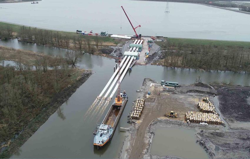
Installation of three 84” pipelines in the
                                                                 nature reserve ‘Biesbosch’, The Netherlands

Table of contents
1.     Business profile Denys ........................................................................................................................................................... 1
2.     Description of the project .................................................................................................................................................... 2
3.     Initial work methodology based on client’s design ......................................................................................................... 3
4.     Improved work methodology .............................................................................................................................................. 3
     4.1.        Prefabrication of double-joints ................................................................................................................................. 5
     4.2.        Set-up and working approach on location ............................................................................................................. 6
       4.2.1.         Transport of the prefab location Dordrecht - project location artificial slope ...................................... 7
       4.2.2.         Pipeline activities on the artificial slope ............................................................................................................. 8
       4.2.3.         Pipeline activities in the dredged trench ........................................................................................................ 13
       4.2.4.         Pull-in ....................................................................................................................................................................... 18
5.     Conclusion ............................................................................................................................................................................. 19

1. Business profile Denys
Denys works and grows according to a vision based on three pillars: diversification, innovation and exportation.
This clearly shows in today’s daily operations of the company. In 2020 Denys employs more than 1800 people,
with branches in different regions home and abroad. In Europe Denys operates in Belgium, The Netherlands,
France, Germany, Poland, Czech Republic, Switzerland, Italy, Denmark and the UK. Further away from home we
are mainly active in the Middle East and Africa.

Denys’ activities are very diverse today and can be classified according to 10 disciplines: high tension cables, high
pressure pipelines, district heating, water (ducts, sewers, treatment plants), tunnelling & drilling, buildings & civil
engineering, renovation, restoration & special techniques, rail works and dream works.

The pipeline department is mainly involved in laying high-pressure pipelines, which has been one of Denys’ main
activities since it was founded in 1923. Thanks to these many years of experience, the department’s know-how
in this matter is quite extensive. With various projects at home and abroad, this department has now become
an important player on the international market.

Within Denys QSHE-MS is our framework which contains
all relevant processes of Denys. These processes run and
interact in a well-managed and controlled manner. It is an
integrated system consisting of integrated procedures and
specific quality, safety and environmental procedures.
QSHE-MS stands for Quality, Safety, Health and
Environmental Management System. It is a certified
management system and is built up in accordance with:
     - ISO 9001:2015
     - ISO 14001:2015
     - ISO 45001:2018
     - ISO 3834-2:2006
     - VCA**2008/5.1

                                                                                                                              Figure 1-1 Denys logo and company

IPLOCA Excellence in Project                                                                                                                                                               Page 1
Execution Award - 2020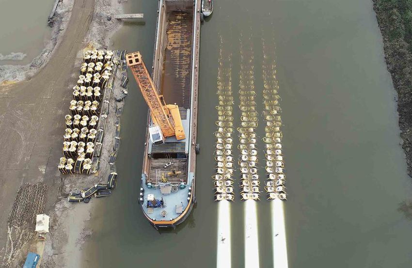
Installation of three 84” pipelines in the
                                       nature reserve ‘Biesbosch’, The Netherlands

2. Description of the project
The project location is situated in the nature reserve (Natura 2000) ‘Biesbosch’ in The Netherlands. Our client
Evides supplies drinking water to 2.5 million consumers and companies in the South-West region of the country
out of the river Maas which acts as a main source. To answer the demand of drinking water three water basins
were constructed in the seventies. The largest basin is known as ‘de Gijster’ with a perimeter of 8km and serves
as a buffer basin where settling of silt and natural purification of organic particles under the influence of light
occurs, thereby improving the initial quality of the raw water.

                                        Figure 2-1 Largest water basin ‘de Gijster’

As the demand of drinking water rises, and will continue to rise further in the future, the initial constructed water
inlet from the seventies is replaced completely by a new water inlet system consisting of a new inlet pump station
and 3 steel water transportation pipelines 84”. The new inlet pump station is located at a distance of
approximately 1.5km from the basin compared to the previous one at a distance of around 100m. This new pump
location guarantees a more stable or constant water quality, resulting in less future effort and energy to purify
the water. The station is located directly adjacent to the river Maas therefor having the smallest environmental
impact on the nature reserve during the construction and maintenance works. The 3 new pumps and pipelines
will each have a maximum flow capacity of 5-8m³/s. To keep the inlet fish friendly the flow threshold will be
limited at 15m³/s in total, meaning that a third pump acts as a redundancy pump to counter delay or standstill
due to breakdown or maintenance of the system.

The scope of works for the construction of this new water inlet system consists of the following activities:
    - Installation of 3 x 84” steel water pipelines from the pump station at the river ‘Maas’ to ‘De Gijster’
        basin
    - Trenching and backfilling under water
    - Connection of the pipelines to the new pump station
    - Installation of the pipeline outlet in ‘De Gijster’
    - Reinstatement of the nature reserve area

                                      Figure 2-2 Project location and pipeline route

IPLOCA Excellence in Project                                                                                 Page 2
Execution Award - 2020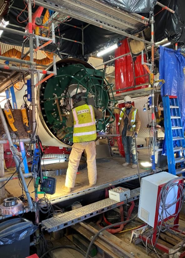
Installation of three 84” pipelines in the
                                       nature reserve ‘Biesbosch’, The Netherlands

Due to the several challenges of the project and the importance of the offshore works during the construction,
Denys decided during prequalification to team up with a specialized and local partner Van Oord, also an Iploca
member. A non-integrated joint venture was founded with Denys as technical and contractual leader.

This document describes only the challenging and innovative execution approach on how these three 84” steel
water pipelines are installed under water in the trench. After this critical operation the pipes are connected with
the future inlet pump station by laying them down in an open trench with sheetpiles.

3. Initial work methodology based on client’s design
The predetermined working method of the client consisted of:
    - Welding of the pipes on the exterior slope of the dike of ‘de Gijster’
    - Floating storage of the pipes in the basin after welding on the dike
    - Pulling of the floating string over the dike in the pipeline trench
    - Floating pull-in of the pipeline in the trench when the total string was assembled

The initial working method had in our opinion significant disadvantages in the aspect of environmental disturbance
and did not comply with the environmental permit due to the following reasons:

    -    Insufficient space on the dike to serve as a welding platform. Therefore significant earthmoving works
         are necessary outside of the project and permit boundaries.
    -    Blockage of the service road on the perimeter around ‘De Gijster’ due to the pull-in of the pipes from
         the welding platform in the basin.
    -    Floating pipeline elements in a drinking water basin with possible contamination risks.
    -    Pull-over on the dike from +6.5m -> +9.5m -> +0.5m. To realize this crossing technical aids are
         necessary:
              o Rollers on the inside slope of the dike → uncertainty of the position as the water level in ‘De
                   Gijster’ fluctuates significantly as a function of demand
              o Temporary support structures to guide the pipelines over a height of approximately 9m and a
                   length of 175m to comply with the bend radius of the 84”pipe → high and signification vibrations
                   to install the piles have a huge impact on the environment and create a risk to induce instability
                   of the dike

                                      Figure 3-1 Originally pipeline support structure

4. Improved work methodology
During tender Denys was already sceptic on the proposed working methodology and we decided to look for an
alternative working method where we were thinking “out of the box”.

IPLOCA Excellence in Project                                                                                 Page 3
Execution Award - 2020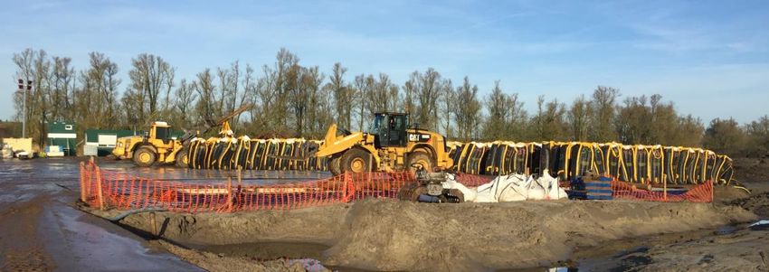
Installation of three 84” pipelines in the
                                            nature reserve ‘Biesbosch’, The Netherlands

Denys and her partner Van Oord has established a new work methodology based on the following cornerstones
to comply with the environmental restrictions, the permits, QSHE and last but not least the tender competition:

    1.   Minimal environmental impact on the Natura 2000 area
    2.   Minimal construction activities in the bassin ‘De Gijster to limit possible decontamination of the water
    3.   Risk based project management system with frequent evaluation of the risks and opportunities
    4.   Minimal risks for Health, Safety and Quality during construction phase
    5.   Minimal construction costs

     Figure 4-1 Inhabitant of the ‘Biesbosch’                                    Figure 4-2 Inhabitant of the ‘Biesbosch’ (2)

IPLOCA Excellence in Project                                                                                                    Page 4
Execution Award - 2020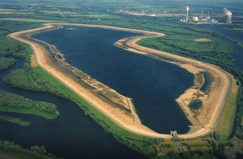
Installation of three 84” pipelines in the
                                            nature reserve ‘Biesbosch’, The Netherlands

    4.1. Prefabrication of double-joints
As the project location is only accessible by transport over water, the welding on this remote location is an
expensive, complex and environmental unfriendly activity. To comply with our predetermined cornerstones the
first modification of the working method is to prefabricate upfront double-joints in a location easy accessible by
road and water transport outside the nature reserve. By applying this methodology 50% of the welding activities
are performed in ideal conditions with zero emissions in the nature reserve.

The PP-coated pipes with a thickness of 22,3/25 mm and a length of 17m were fabricated in Spain, transported
by cargo vessels and delivered to Van Leeuwen pipes at the quay of ‘Zeehavenbedrijf Dordrecht’ (ZHD). In
Dordrecht the pipes were unloaded on the quay wall, transported directly on trucks and stored at the pipe
storage area located on the site of ZHD itself. The best location to prefabricate the double-joints is thus the
storage area itself. This prefab location gives us a controlled and easy accessible environment to gain experience
with these large diameter pipes in the respect of fitting, welding, coating, handling and transportation.

On the pipe storage area two welding streets are assembled to guarantee an optimal efficiency of personnel and
equipment. A welding street with a length of approximately 100m consists of a steel foundation structure with
mounted rollers, 1 welding shack, 1 coating shack and a holiday test brush. A single pipe with a length of 17m is
placed on the first rollers. The first rollers are hydraulic-driven and shift the pipe through the welding tent after
which the second pipe was positioned next to the previous one by the same method. The hydraulic driven-rollers
can shift the pipe upwards and sideways and can rotate it at a certain speed, thereby replacing the need of an
internal/external clamp for the fitting. Another advantage of the rollers is that the welds, aside from the root
pass with STT, can be done by the use of a pendulum (MCAW) on top of the pipe as the pipe could rotate by
the rollers. This method improved the welding speed and the welding quality of the significantly. This showed
itself in a final result of only 3 small repairs (at the same location) on 108 welds (3% repair rate).

       Figure 4-3 Double-joints prefab location in Dordrecht                  Figure 4-4 Rails & rollers set-up, welding tent

Once the weld is approved by the NDT-procedure (TOFD), the double-joint is shifted forward again by the
rollers until the weld is in the center of the coating shack. In this shack the weld is being sandblasted and PP-
coating applied by the use of PP-flamespray by Eupec Pipecoating France (Iploca-member). The coated weld is
controlled by a holiday test and after a positive result the complete double joint is shifted through the holiday
test brush to detect discrepancies in the coating. When no imperfections are encountered the pipe is shifted to
its final position at the end of the welding street and placed back on the stockpile, ready for transport by vessel
to the working area in the ‘Biesbosch’ reserve.

IPLOCA Excellence in Project                                                                                                    Page 5
Execution Award - 2020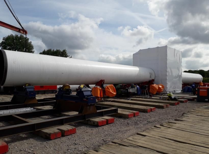
Installation of three 84” pipelines in the
nature reserve ‘Biesbosch’, The Netherlands
Figure 4-5 MCAW with pendulum Figure 4-6 Pipe handling on the double jointing yard
Working upfront on this prefab location gave us the necessary experience and time for optimization to properly
prepare and efficiently start the assembly on the remote project location in the ‘Biesbosch’.
4.2. Set-up and working approach on location in the nature reserve
To minimize the disadvantages of the predetermined working method of the client and to comply with our
cornerstones the following adjustments were proposed and approved:
Installing an temporally artificial slope in sand on the exterior of the dike as an alternative for the piles
Installing a triple welding and coating station on this slope within the boundary limits of the project and
permit
The main principle of this working approach is as follows:
1. Transport the double-joints over water by vessel
2. Unloading on the maintenance quay wall close to the basin
3. Transport of the double joints over the dike to the project location or artificial slope
4. Positioning of the double joints on the slope
5. Fitting, welding, coating, non-destructive testing of the double joints
6. Pull-in 1 double joint (34m) per work station and per day in a trench with depth of ± 5m,
By this working approach based on the 2 improvements came 1 significant disadvantage. The channel
‘Spijkerboor’, located in the middle of the spread, will be blocked from the moment the string reaches the
‘Spijkerboor’ until the filling and submerging of the pipelines are done, resulting in a significant obstruction time
period for the shipping on this channel. In the permits the maximal obstruction time for shipping traffic was
maximized to 6 weeks.
To avoid this issue an alternative was sought and found in the appliance of the off-bottom tow method. This
method is established by a combination of
- adding weight, in the form of sand, in a specific designed geotextile saddle bag over the pipe forcing the
pipe to sink to the trench bottom. This saddle bag was designed and produced in close collaboration
with Pipe Sak, also an Iploca-member.
- attached short anchor chains (85cm) at the bottom of the bag, which will rest partly on the trench
bottom to add or lose weight by leaving more or less chain on the bottom when fluctuations of water
density due to tides, pipe thickness, sand density in the bag, chain weight etc. occur
IPLOCA Excellence in Project Page 6
Execution Award - 2020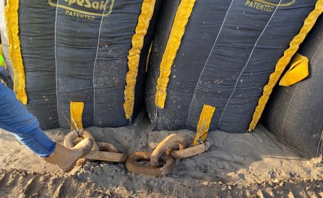
Installation of three 84” pipelines in the
                                          nature reserve ‘Biesbosch’, The Netherlands

    -    longer chains (13m) at certain distances to obtain a stable entity resistant against external forces of
         current, tide, wind…

This combination allows the pipe strings to float in a stable manner on a distance of approximately 50cm from
the trench bottom.

             Figure 4-7 Off-bottom tow principle                              Figure 4-8 Channel ‘Spijkerboor’ passage

The off-bottom tow method required some additional steps in the working approach before pull-in:

    7.   Filling of the saddle bags with sand, weighing under water, attaching the chains
    8.   Installing the saddle bags and chains over the pipe
    9.   pull-in 1 double joint (34m) per day in a trench with depth of ± 5m

         4.2.1. Transport of the prefab location Dordrecht - project location artificial slope
From the prefab location at ZHD the double-joints are loaded on a pipe truck, transported to the quay wall and
transferred via the quay handler crane to a specially equipped pipe pontoon with spacers and pegs. The pontoon
is loaded by a maximum of 7 double-joints in 2 rows and is towed afterwards from Dordrecht to the nature
reserve by a tugboat. On arrival the pontoon is moored against the quay wall of the ‘Kerksloot’.

           Figure 4-9 Pipe loading storage area                                 Figure 4-10 Pipe loading quay wall

At the ‘Kerksloot’ a 250Te-crawler crane lifts the pipes on the quay. Each pipe is transported individually by an
SPMT (Self Propelled Modular Transporter) over the dike from the ‘Kerksloot’ to the artificial slope with a driving
distance of approximately 4km. The advantages of the use of an SPMT over normal transport are:
     - Transport in a very controlled and stable manner as each trolley and/or axle can be controlled
         individually
     - Less axle load during the transport on the asphalt of the dike
     - Less axle load during the crossing of the pre-existing inlet pipelines from the seventies at ‘Kerksloot’
     - Easily drivable in all directions – due to insufficient turning space on the slope and the interdiction to
         drive on the complete perimeter of ‘De Gijster’ dike because of nitrogen oxides emission limitations
     - Increase pipe storage capacity on ‘Kerksloot’ by appliance of a bogmat set-up to ensure selfloading
         capacity of the SPMT out of range of the 250Te crawler crane – ref. picture 4-13

IPLOCA Excellence in Project                                                                                             Page 7
Execution Award - 2020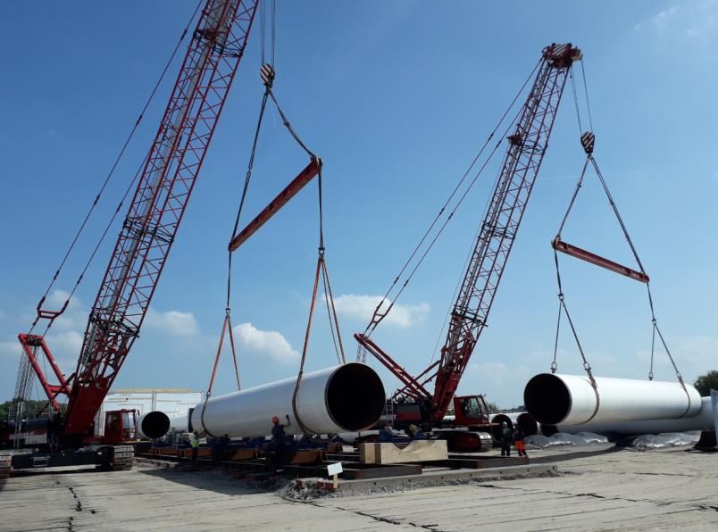
Installation of three 84” pipelines in the
nature reserve ‘Biesbosch’, The Netherlands
Figure 4-11 Unloading pipe pontoon at the ‘Kerksloot’ Figure 4-12 Pipe transport route
Figure 4-13 Bogmat set-up ‘Kerksloot’ to increase storage capacity Figure 4-14 SPMT driving on dike
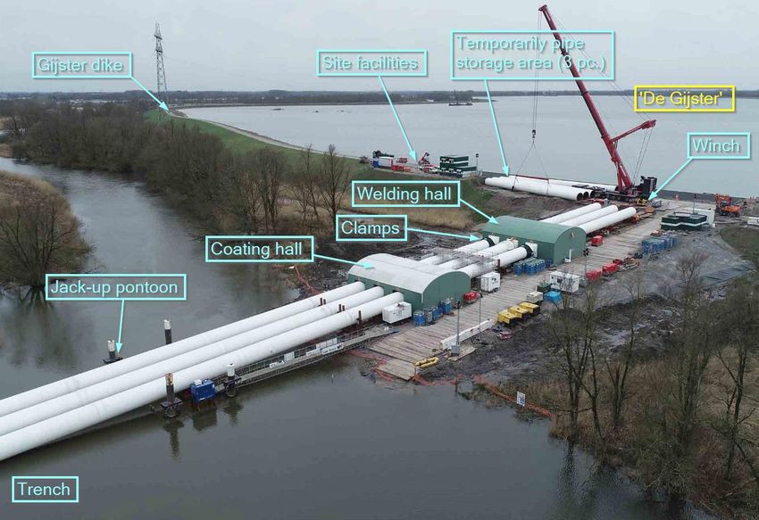
4.2.2. Pipeline activities on the artificial slope
The slope set-up consists mainly of the following components which is installed in a triple parallel production
line:
- Temporarily pipe storage area
- Welding hall, completely closed to ensure welding quality and minimize noise, light and other emissions
in the reserve
- Coating hall, completely closed to ensure coating quality and minimize noise, light and other emissions
in the reserve
- Driving platform
- Rail and rollers system
- Hydraulic clamp 84”
- Winches
- Jack-up pontoon and double hinged rollers
IPLOCA Excellence in Project Page 8
Execution Award - 2020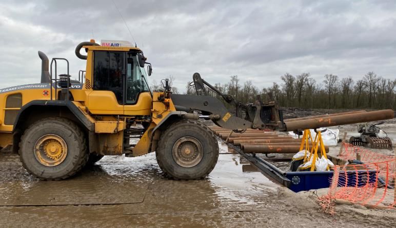
Installation of three 84” pipelines in the
                                        nature reserve ‘Biesbosch’, The Netherlands

                               Figure 4-15 Temporary slope set-up with different components

In front of the pipelines specific pulling heads are installed. These pulling heads of 84” are designed and
manufactured according to the expected pulling force and are foreseen with flanges for the filling of the pipelines
with water in the final phase of sinking them to the bottom of the trenches.

The first step of the pipeline activities on the slope is to shift 3 pipes from the temporary pipe storage area to
the rails and rollers system. Due to the significant weight of the double-joint (± 42 tons) this is done by a 500Te
telescopic crane. When the pipe is positioned on the rollers, a steel wire connected to a winch is attached at the
back of the open pipe end. The use of the winch is to prevent that due to its own weight and the angle of the
slope (3° or 1/20) the pipe would slide, uncontrollably, forward. It also acts in the first days of pipe launching as
a counter-force or break during pipe pull-in.

IPLOCA Excellence in Project                                                                                 Page 9
Execution Award - 2020
Installation of three 84” pipelines in the
nature reserve ‘Biesbosch’, The Netherlands
Figure 4-16 Installation of a double-joint on the first hydraulic- Figure 4-17 Pipe lifting in front a the welding hall
driven roller section
Before the pipe can shift forward by giving slack to the winch
wire, the internal 84” clamp needs to be in position. The
internal clamp is pneumatically-driven by a high pressure
compressor connected to an expansion vessel to cover the
complete length of a double-joint. The three hydraulic clamps
were custom made by OPUS SRL in Italy (Iploca-member). The
fitting of both double joints is done by combination of the
internal clamp and the hydraulic-driven rollers. To avoid or
minimize environmental impact the bevels are being
brushed/cleaned inside the hall.
When the pipes are properly fitted and aligned the welding can
start. The welding process on location is known as STT-
FCAW(CRC), where the root pass is executed by the semi-
automatic STT-procedure and the other passes with automatic
flux-cored arc welding (FCAW) with CRC-bugs (Iploca-
member). The weld is made by 2 welders per string or 6
welders in total for the complete set-up. The key advantages
of this welding procedure is productivity, weld quality,
consistency, ease of use, short training time and reliability. This
is shown as in full production the duration of the welding itself
takes approximately 4 hours and the repair rate is negligible.
The welds are non-destructive tested by ultrasonic testing, or more specifically TOFD (Time-Of-Flight-
Diffraction). Figure 4-18 Pipe fitting with internal clamp
IPLOCA Excellence in Project Page 10
Execution Award - 2020Installation of three 84” pipelines in the
nature reserve ‘Biesbosch’, The Netherlands
Figure 4-19 FCAW with CRC bug Figure 4-20 FCAW with CRC bug (2)
In the other hall the welds of the previous day are being coated. The coating is applied by Eupec Pipecoatings
France using the PP-flamespray method and is a combination of Fusion Bond Epoxy (FBE) in the first layer and
Copolymer Modified PolyPropylene (CMPP) as a second layer. Similar to the welding procedure, the coating
procedure proves to be a consistent, productive, reliable and qualitative method.
Prior to the application of the PP-flamespray the weld requires sandblasting Sa 2 ½ coarse grade and preheating
to a temperature between 180° and 250°. Preheating is done by an induction coil connected to a 350kW
induction generator. The coating works are finalized with a positive 25kV Holiday Test of the weld itself by fixed
brushes on the coating set-up.
Figure 4-21 Coating with PP-flamespray Figure 4-22 Coating with PP-flamespray (2)
The final significant area on the slope is the jack-up pontoon and the double hinged rollers. These items fulfill a
double function, more specifically preserving the:
1. Pipe integrity by limitting peak stresses on the pipe and the coating
2. Stability at the toe of the temporary slope
During launching of the first 4 segments, the forces on the pipe and consequently to the rollers, rails and soil are
quite high due to the large span between the last support (roller) and the water (level). These significant forces
are even higher during a low tide period, as this span increases. In extremum, one can note that highest forces
are encountered when the cantilever is at its maximum, or more specifically just before the pipe reaches the
water surface.
To decrease or at least resist the forces by a method aligned with our cornerstone of minimizing environmental
impact (no vibrations etc.) an extra intermediate support is installed by means of a roller on a jack-up pontoon.
IPLOCA Excellence in Project Page 11
Execution Award - 2020Installation of three 84” pipelines in the
nature reserve ‘Biesbosch’, The Netherlands
The jack-up pontoon can position itself on a certain level independently of the fluctuating tide. By applying this
extra support the forces are decreasing substantially but not sufficiently to limit the pressures on the toe of the
slope and to preserve the integrity of the large diameter pipe with a relatively small wall thickness (22.2mm).
Three double hinged rollers are minimally required to cope with the bending forces in the pipeline and to prevent
buckling of the pipe. By this hinge between the rollers there is always a maximum support surface from the roller
to the pipe bottom.
Figure 4-23 Pipe launch sketch, slope toe detail
Figure 4-24 Jack-up pontoon with rollers Figure 4-25 Double hinged rollers
The final important item on the slope are the breaking clamps. These specific clamps are designed and
manufactured inhouse Denys. They are hydraulic-driven and prevent any pipe movement on the slope induced
by forces acting on the underwater pipeline part due to current, tide and wind. The only moment the clamps are
open is during the pull-in phase. Similar as the use of the winch, the use of the clamps is particularly important
during the pull-in of the first 4 segments as the pipe is not stabilized in the water yet and wants to slide downwards
due to its own weight and the angle of the slope. This crucial phase is explained in detail in the next chapter.
IPLOCA Excellence in Project Page 12
Execution Award - 2020Installation of three 84” pipelines in the
nature reserve ‘Biesbosch’, The Netherlands
Figure 4-26 Hydraulic-driven breaking clamps Figure 4-27 Hydraulic-driven breaking clamps (2)
4.2.3. Pipeline activities in the dredged trench
As mentioned earlier, a solution to prevent an obstruction
of the channel ‘Spijkerboor’ was found in the appliance of
the off-bottom tow method. To establish this, the pipeline
is firstly ballasted until it sinks and will subsequently, just
before reaching the trench bottom, stabilize as the short
chains will leave more or less chain length on the bottom.
According to the calculations, a certain underwater ballast
of 2350 kg/m is required to reach the tipping point of
sinking the pipeline. To achieve this in a cost-efficient, easy
executable and reliable manner geotextile saddle bags, or
PipeSaks, are used. The main advantage of this product is
that the PipeSaks can be filled with a good quality sand on
site located in the lower layer of the dredged trench and
that the design of the PipeSaks can be adjusted to our Figure 4-28 PipeSak sketch
specific needs.
Finally after an intense engineering and several trials, the PipeSaks have the following dimensions to comply with
our required weight per meter:
- Length = ± 1.13m
- Height = ± 2.3m
- Width = ± 0.7m
With this length of 1.13m the required underwater weight is 2.655 kg per bag. Based on the calculations it is
noted that the tolerances on this predetermined weight are very delicate. To state it quantitively on a bag of
2.655kg, the margins are +40kg/-80kg. One can note easily that these margins are very narrow taking into account
the high number of variables such as the sand density, the PipeSak dimensions, the filling and compacting method,
the wall thickness of the pipes, the water density,… Due to this delicateness, the decision is made to weigh all
PipeSaks underwater prior to installation on the floating pipelines. This to monitor closely the ballasting weight
at any given moment as this phase is the key to success for the project.
To equalize the ballasted pipeline at a short distance from the trench bottom, short chains of 85cm are used.
These typical anchor chains have a diameter of 62mm and a weight of 57kg for this specific length of exactly 3
shackles. The chains are connected on each side of the PipeSak via a sewn loop (item D1 on the PipeSak-sketch)
by using 2 heavy duty tie-wraps.
IPLOCA Excellence in Project Page 13
Execution Award - 2020Installation of three 84” pipelines in the
nature reserve ‘Biesbosch’, The Netherlands
Figure 4-29 Short chains of 85cm attached by tie-wraps Figure 4-30 Long chains (13m)
Next to the short chains longer chains of 13m are used. These longer chains are positioned over the pipe with
their chain ends touching the trench bottom over a length of approximately 2 - 4m thereby acting as a sort of
anchor and creating extra stability on the pipeline against external forces such as tide, current, wind…
IPLOCA Excellence in Project Page 14
Execution Award - 2020Installation of three 84” pipelines in the
nature reserve ‘Biesbosch’, The Netherlands
The ballast scope can longitudinally be split up in 2 main areas as per the sketch below taking into account the
fact that the shipping on the channel cannot be interrupted.
1. Starting from pull-head over a length of ± 600m (green area): PipeSak saddle bags side-to-side & anchor
chains (long + short)
2. Remaining length of ± 600m (purple area): only saddle bags PipeSak side-to-side & no chains
Figure 4-31 Longitudinal scope split
The idea of still adding PipeSaks in the second part of the pipeline is to reduce the pipe surface above the water
level and so limiting the acting wind forces on this surface or eventual subsequent movement on the slope during
construction works. If no PipeSaks are installed, the pipe would be 2/3th above the water level, easily prone to
wind forces.
Summarizing the required calculated quantities for the ballasting system, we come to the next figures:
- A total of 3200 custom-made PipeSaks
- 3000 short anchor chains, 90 long anchor chains, in total a weight of ca. 250 tons
- Daily required installed number of 90 PipeSaks, 180 short anchor chains and 6 long chains
It can easily be understood that the working method for the ballasting on site needs to be fast, reliable, sustainable
and qualitative to avoid any delay or standstill for the pipeline operations on the slope.
To accomplish a fast and consistent filling of the PipeSaks, two filling frames are designed and constructed. These
filling frames were thoroughly tested in the workshop to determine the best position for the connection points
of the loops and the dimensions of the support frames in order to widen the fill opening to its maximum and to
allow the maximum elongation in the height direction. At the bottom of the frame a platform is installed with a
vibro-motor. This platform has a double function: creating support of the saddle bags to prevent eventual rupture
due to its substantial elongation and compaction of the sand during the filling process. The filling frames are
provided with a storage space for a full package of empty saddle bags, collective safety measures and a working
platform around the saddle bags for the laborer’s.
IPLOCA Excellence in Project Page 15
Execution Award - 2020Installation of three 84” pipelines in the
nature reserve ‘Biesbosch’, The Netherlands
Figure 4-32 PipeSak filling set-up Figure 4-33 PipeSak filling set-up (2)
A 50 tons excavator, equipped with a special bucket, is taking care of the actual filling. This bucket has also a
vibro- motor, to facilitate the flow of sand through the bucket, and two individual hydraulic-controlled valves, to
finetune the filling process per saddle bag. The excavator positions itself on the sand bund to maximize the
viewing range of the operator during the filling process and to easily access its filling material.
When the PipeSak is filled, the wheel loader removes the PipeSak from the frame and transports it to the water
containers set-up. As mentioned earlier all PipeSaks are weighed underwater to monitor the ballast process
carefully. Via a balance mounted on each side of the wheel loader’s fork the exact weight is registered. Two
weights are registered per side, the ‘dry’ weight before submerging in the water and the ‘wet’ submerged weight.
To register the ‘wet’ weight, experience on site showed that a constant weight is gained only after being at least
20 mins submerged. This period is necessary to replace the air filled voids between the sand grains with water.
After weighing, the PipeSak is transported to the storage area until further notice. The tubular profiles are used
to remove the filled PipeSak out of the frame and to support it in the water containers as these can be easily
taken with the wheel loader.
Figure 4-34 Determining the ‘wet’ weight Figure 4-35 Tubular profils
IPLOCA Excellence in Project Page 16
Execution Award - 2020Installation of three 84” pipelines in the
nature reserve ‘Biesbosch’, The Netherlands
Figure 4-36 PipeSak storage area
To install the filled PipeSaks on the pipeline a self-propelled crane vessel with hopper is used. The vessel positions
itself between the floating pipelines and the shore with 2 spuds. To respect the pipe’s elastic radius the PipeSak
installation position is calculated on approximately 100m from the slope and stays constant over the duration of
the ballast scope. After the engineer’s approval concerning the ‘wet’ weight of the PipeSak, it is transported from
the storage area to the temporary smaller storage area close to the trench and in reach of the crane on board
of the vessel. The PipeSaks are positioned and installed in a certain constant order so that at any given time the
correct amount of ballast per pipe string can be derived from the registrations in the spreadsheet. To simplify
the rigging a quick-release spreader is developed specifically for this job. The crane operator can open the hooks
from within the cabin when the load is off the spreader, or in other words when the PipeSak is positioned and
resting on the pipe.
Figure 4-37 PipeSak installation with crane vessel Figure 4-38 Specific designed spreader
IPLOCA Excellence in Project Page 17
Execution Award - 2020Installation of three 84” pipelines in the
nature reserve ‘Biesbosch’, The Netherlands
Figure 4-39 long chain installation with crane vessel Figure 4-40 PipeSak installation with crane vessel (2)
4.2.4. Pull-in
When the coating holiday test results are positive and the double-joint section which is in the water is properly
ballasted, the pull-in procedure can start. During the daily pull-in the pipes are moved in the trench over a length
of one double-joint (34m) by means of hydraulic-driven winches. The pull-in approach is split in two phases:
- Phase 1: slope toe → walking dike (± 550m)
- Phase 2: walking dike → trench end (± 650m)
The idea behind this scope-split is related to the existence of the walking dike adjacent to the channel
‘Spijkerboor’. The main advantage of leaving the walking dike intact as long as possible is to minimize
sedimentation in the dredged trench. When the dredged trench is blocked on one site, the current and
subsequent sedimentation in the trench is reduced to a minimum. This is crucial as dredging or excavating under
the floating pipelines to remove eventual sedimentation is very difficult and risky.
Figure 4-41 Pull-in split scope
According to the calculation a maximum pulling force of 47tons per pipeline string is required. The necessary
pulling force is calculated based on the weight of the chains anchored partly in the trench bottom. Based on these
calculations, three 80tons winches are deployed. To work properly, the winches must transfer their reaction
force to the subsoil. In general this task is normally fulfilled by installation of sheet piles or tubular piles at a
certain depth.
To align our works in the first phase in the proximity of the walking dike with our predetermined cornerstone
to reduce environmental impact (vibrations), dredge anchors are applied and installed in the ‘Spijkerboor’. As the
set-up of the winches needs to be in line with the designed pipeline direction, a pontoon is anchored against the
interior (opposite ‘Spijkerboor’) of the walking dike with all the pulling measures aboard.
IPLOCA Excellence in Project Page 18
Execution Award - 2020Installation of three 84” pipelines in the
nature reserve ‘Biesbosch’, The Netherlands
Figure 4-42 Winch pontoon (phase 1) Figure 4-43 Winch pontoon (2)
Figure 4-44 Mainland winch set-up (phase 2)
In the second phase the three winches are installed on the main land. The reaction force is easily gained by
appliance of sheet piles. The installation of sheet piles in the area of the construction works of the pump station,
adjacent to the channel ‘Maas’, is in line with the permits and environmental restrictions in this area.
Per pipeline string a specially designed pull-head is welded on the first pipe which is connected to a multilug
(spreader) via steel ropes. On the multilug the winch wires are attached. A buoy with a buoyancy of 6tons is
connected to the multilug giving it the necessary buoyancy to avoid ploughing in the trench bottom during pull-
in.
Figure 4-45 Multilug with buoy Figure 4-6 Pull-heads with welded spacer profile on top
5. Conclusion
This project is due to the huge diameter steel pipelines and its onshore/offshore character a very exclusive and
challenging one. Denys’ employees love such challenges since it allows them to show their ability to find pragmatic
solutions for each problem. Cutting edge and thinking in solutions are our credo’s.
IPLOCA Excellence in Project Page 19
Execution Award - 2020Installation of three 84” pipelines in the
nature reserve ‘Biesbosch’, The Netherlands
This is the reason why Denys was eager to score this unique project in our backyard and by “thinking out of the
box” we managed to win the tender based on our economically most advantageous offer with very high scores
on the following criteria : risk reduction, minimal emissions, permitting, asset quality, planning and cost. After
award we proved to the client and the local stakeholders that what we had in mind could be transformed in a
successful and safe work methodology.
The limited experience within Denys related to ‘offshore’ works and 84” steel pipes was one of the challenges
we had to overcome. Because of this, and our doubts regarding the client’s initial design, we optimized it
significantly through intensive engineering efforts during the preparation period and later during execution as
well. All these optimizations are based on the principle of being in line with our predetermined cornerstones of
minimal environmental impact in the Natura 2000 area and minimal construction activities in ‘de Gijster’ basin.
The benefit of intensive engineering proofed itself, next to positive feedback regarding environmental protection,
in excellent production results under safe working conditions.
Denys is not only proud on the way they won this tender but for sure also that it all worked out as our brilliant
and enthusiast engineers had in their mind. Our team found technological solutions for each challenge of the
project, going from the remoteness of the area and the logistic difficulties, only accessible over the water, and all
this in, and with respect for, a wonderful environmental area of our planet, the nature reserve “Biesbosch”
preserved as a Natura 2000 park by the European Union.
To achieve our goals we teamed up with several partners, from whom the majority are also Iploca members.
Due to initiatives such as the Road to Success and the Conventions we met other entrepreneurs with the same
passion for results. On this project we proofed that the mission of the Association works : retaining and sharing
knowledge globally, facilitating business opportunities, and promoting the highest standards in safety, innovation,
quality, business ethics and sustainability throughout the pipeline construction industry.
Denys decided to introduce this project as a submission for the “Iploca Excellence in Project Execution Award”
as a recognition for the excellent performance of the several teams working day and night on this exclusive
project with continuous respect for our safety and quality standards with a satisfied client as result.
IPLOCA Excellence in Project Page 20
Execution Award - 2020You can also read