Specifying HV/MV Transformers at Large Sites for an Optimized MV Electrical Network
←
→
Page content transcription
If your browser does not render page correctly, please read the page content below

Specifying HV/MV Transformers at
Large Sites for an Optimized MV
Electrical Network

White Paper 258
Revision 0

by Juan Tobias
   Daniel Radu
   Philippe Dogny
  Jean-Luc Belletto

       Executive summary
       Generally, large industrial site designs use standard
       specifications of the HV/MV transformer which leads to
       oversizing and a higher cost of the MV primary and
       secondary electrical distribution system. This paper
       introduces the factors to consider when specifying the
       HV/MV transformer and raises awareness of the impact
       of short circuit impedance (zt) on the cost of the HV/MV
       transformer and the MV electrical distribution installa-
       tion (MV switchgear and cabling). Finally, a case study
       of a large date center is presented to show how a
       reduction in the total cost of ownership (TCO) can be
       achieved. NOTE: this technical white paper is aimed at
       electrical engineers who are specifying HV/MV
       transformers for large industrial and data center sites.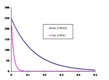
Schneider Electric – Data Center Science Center        White Paper 258 Rev 0         2

Introduction                      Electrical utilities use four types of networks topologies to deliver electrical energy
                                  to the different types of load centers. The main network characteristics are pre-
                                  sented in Table 1.

Table 1
Network characteristics of the four utility network topologies used to deliver energy to load centers

                                                                        Nominal Voltage           Main        Typical
           Network Type                    Function
                                                                         (typical range)        topology     Availability
       Extra High Voltage    Transport bulk power over long
                                                                      800kV < Un < 220kV         Meshed      99.99999%
       (EHV) transmission    distances
                             Distribute power to main consump-
       High Voltage (HV)
                             tion centers (cities, large industrial    220kV < Un < 52kV         Meshed       99.9999%
       sub-transmission
                             sites, and infrastructure sites)
       Medium Voltage        Distribute power within urban and                                 Open Ring
                                                                       52kV < Un < 7.2kV                       99.99%
       (MV) distribution     rural areas                                                       and Radial
       Low Voltage (LV)      Distribute power to residential
                                                                              400V               Radial          99%
       distribution          customers

                                  The voltage level selected to connect large industrial and infrastructure site loads
                                  depends on:

                                     • Network voltage level available at the site
                                     • Maximum power demand requirements, including future expansions
                                     • Short circuit current level required for “direct on line” (DOL) starting of large
                                       MV motors

                                  Figure 1 indicates that loads in the range of 20 to 100 MVA will be connected to the
                                  HV sub-transmission network at voltages between 66 kV to 150 kV. The actual con-
                                  nection voltage will vary country by country since electrical utilities adopted differ-
                                  ent voltages when they constructed their networks more than 50 years ago.

                                  Industrial sites such as mines, oil & gas refineries, paper mills, cement plants, as
                                  well as large infrastructure sites like major airport hubs (e.g. London Heathrow,
                                  Paris CDG, New York JFK, etc.) have always been connected to the utility HV sub-
                                  transmission network since their installed power exceeds 20 MVA. More recently,
                                  XL data centers built by Web Giants (e.g. Google, Amazon, Facebook) and large
                                  colocation and telecom companies (e.g. Equinix, Interxion, Telefonica, etc.) could
                                  be considered as being “large infrastructure” installations as they are connected to
                                  the HV sub-transmission network.

Figure 1
Electrical utility network
voltage connection of
large loads (> 20 MVA
maximum demand)

 Specifying HV/MV Transformers at Large Sites for an Optimized MV Electrical Network
Schneider Electric – Data Center Science Center White Paper 258 Rev 0 3
This paper intends to raise awareness among these groups of end users on how to
specify the key parameters of the HV/MV transformer to optimize the total MV distri-
bution network cost. Particular emphasis is put on the choice of HV/MV trans-
former short circuit impedance (zt) value as it has the highest impact on the cost
and performance of the site MV electrical installation. The paper focuses on 3
phase HV/MV oil-filled transformers.
A synthesis of IEC and ANSI/IEEE standards guidelines applicable to HV/MV oil-
filled transformers is provided. The different philosophies of both standards and the
impact they have on the customer specifications in the USA and the rest of the
world (RoW) are explained and illustrated with an example of a typical 40 MVA, 132
KV/11 KV, DY11 oil-filled transformer.
Finally, the paper shows a comparative analysis of the combined cost of HV/MV
transformer, MV switchgear and MV cabling for a typical large data centre (80 MVA
installed capacity) for different values of HV/MV transformer short circuit impedance
(zt). The analysis clearly illustrates that specifying the right zt value in the design
phase is key to optimizing the cost and performance of a large site’s MV electri-
cal installation.
General The main parameters that define the electrical performance of a 3 phase HV/MV oil-
filled transformer are:
considerations
• Primary and secondary rated voltage (U1r and U2r)
• Nominal apparent power (Sn) with the associated cooling method (natural or
forced)
• Vector group (e.g. Dy 11)
• Short circuit impedance zt in %
• Regulation range and type
• Frequency
• Losses
Important ancillary items required to complete the HV/MV transformer specification,
such as connection systems (bushing, cable), the use of a conservator, Buccholz
relay, temperature monitoring, dissolved gas monitoring equipment, noise require-
ments (no-load, load and/or total noise), and special insulating fluid will not be dis-
cussed in the paper as they only impact the HV/MV transformer cost.
Metering location
In most countries the end user requiring an HV network connection has to enter into
a negotiation with the local electrical utility to fix the cost of the connection from the
site to the point of common coupling. The utility is likely to propose their standard
type of HV/MV substation.
The “metering point” divides the electrical plant ownership between the utility and
the end customer. Utilities specify and purchase the metering CT and VT, as well
the kWh meter used for billing. They also supply the back-up circuit breaker that will
disconnect the end user installation from the HV grid in case the HV circuit breaker
on the end user side fails to clear a fault within its own network.
In general, utilities prefer to provide metering on the MV side of the transformer.
However, in some countries the end user can request to have the “metering point”
Specifying HV/MV Transformers at Large Sites for an Optimized MV Electrical NetworkSchneider Electric – Data Center Science Center White Paper 258 Rev 0 4
on the HV side of the transformer, as illustrated in Figure 2. In this arrangement, the
end user has a lower kWh tariff but has to specify and purchase the HV/MV trans-
former and HV switchgear. The end user would also have the responsibility for the
maintenance of the HV installation in this case.
Although initially there is a higher capital investment, the end user can expect pay
back between 3 to 5 years as the price of kWh as an HV customer is significantly
lower than the MV tariff. Furthermore, the end user can further benefit by choosing
an HV/MV transformer specification that cost reduces the total cost of its MV distri-
bution installation. This specification needs to be done very early in the project as
the HV/MV transformer is an engineered to order (ETO) item with typically the long-
est lead time (usually 6 to 8 months).
Figure 2
HV/MV substation with
HV utility metering for
connection of a site with
installed power > 30
MVA
NOTE: Bus section circuit breaker can be « normally open » if no need for MV motors with DOL start
NOTE: Site load is equally shared between HV/MV transformers
HV/MV Transformer short-circuit impedance
transformer The transformer short circuit impedance (zt) is a fundamental value measured,
specification guaranteed, and reported on the nameplate for all transformers in percentage (%).
However, many people specify transformers without fully understanding the impact
of this key parameter on the total cost of the MV installation.
The magnitude of zt is the voltage drop caused by the transformer leakage imped-
ance at full load current, expressed in % of the rated voltage. It can also be repre-
sented as the % of the rated primary voltage (U1r) that has to be applied (U1sc) to
circulate full load current (I2R) when the secondary winding is under short circuit
condition (see Figure 3). For this reason zt is also referred to as “short circuit volt-
age impedance“ and expressed as 1:
zt (%) = (U1sc / U1r) x 100
Figure 3
Basic circuit used to
measure transformer
short circuit impedance
zt in %
1 A. Naderian Jahromi, J. Faiz and H. Mohseni, A fast method for calculation of transformers leakage re-
actance using energy technique, IJE Transactions B: Applications, Vol. 16, No. 1, April 2003
Specifying HV/MV Transformers at Large Sites for an Optimized MV Electrical NetworkSchneider Electric – Data Center Science Center White Paper 258 Rev 0 5
The short circuit impedance zt is determined by the leakage flux which depends on
the winding characteristics and the leakage flux magnetic path. These are parame-
ters that can be varied during product design engineering by choosing different coil
designs and geometries.
Physically, the short-circuit impedance relates with the leakage inductance (Llk) of
the energized winding added with the leakage inductance of the shorted winding(s)
(scaled according to the turns ratio).
Accurate calculation of leakage inductance for a given design requires 3D mag-
netic field computations using finite element method. However, it is possible to
have an estimation of leakage inductance using different analytics methods (See
Footnote 1). Among these methods the one named “energy method” presents the
most accurate evaluation of the leakage inductance. The equations given by this
method are shown and used below for the evaluation of the short circuit impedance
zt.
We know that short circuit transformer impedance (Zt) in ohms is given by 2:
zt (%) U1r 2
Zt =
100 Sn
And 3 Zt ≅ Xt = 2 ∙ π ∙ f ∙ Llk
…where Rt is neglected as the Xt>>Rt for large transformers.
Hence, from these equations above and also considering the leakage inductance
(Llk) given by the following equation 4 (see Figure 4):
D e D e 1
L lk = 2πµ0 N 2 * 1 1 + 2 2 + D12 e12 *
3 3 H
(4)
…we obtain the short circuit impedance of the transformer 5:
D e D e 100 * n c
z t (% ) = K * 1 1 + 2 2 + D12 e12 * f * (NI)² *
3 3 H * Sn
(5)
Where:
zt = transformer short circuit impedance (%)
K = coefficient
D1 , D2 = average diameters of respectively MV, HV windings (mm)
D12 = average diameter of the gap between the windings (mm)
e1 , e 2 = thickness of MV and HV windings respectively
e12 = gap between the windings (mm)
2 Robert M. Del Vecchio Bertrand Poulin Pierre T. Feghali Dilipkumar M. Shah Rajendra Ahuja, Trans-
former Design Principles : With Applications to Core-Form Power Transformers, Second Edition, Edi-
tion 2, CRC Press, 2 June 2010
3 Standard IEC 60076-8 - Power transformers – Application guide, 1997
4 C57.12.10-2010 - IEEE Standard Requirements for Liquid-Immersed Power Transformers
5 Standard IEC 60076-1- Power transformers – General, 2011
Specifying HV/MV Transformers at Large Sites for an Optimized MV Electrical NetworkSchneider Electric – Data Center Science Center White Paper 258 Rev 0 6
f = frequency of network (Hz)
NI = ampere-turns of HV or MV winding
nc = number of columns of stacked transformer
H = height of HV windings (mm)
Sn = transformer nominal apparent power (kVA)
D1
D12
Figure 4
Axial structure of H
simple 2 windings D2
e1 e2
e12
In order to receive a quotation, customers have to specify the value of zt in % as
well as other key parameters that define the transformer specification (V1r, V2r, Sn,
connection group, etc.). The manufacturer will try to achieve the most cost effective
transformer design by adjusting:
• Winding geometrical parameters:
o number of turns (zt is proportional to the square of the number of
turns),
o height (zt is proportional 1/height),
o gap between windings,
o winding diameter
• Resistive part of the winding (for resistive part of short circuit impedance zt)
The magnitude of zt has a major impact on the performance of the MV electrical net-
work, namely:
• Magnitude and waveform of the short circuit current in the secondary side
• Voltage drop under load conditions, also known as “voltage regulation”
• Magnitude of magnetizing inrush current
• Capacity to share load between two or more transformers connected in paral-
lel
Impact of “zt” on MV short circuit current
The maximum short circuit current that a transformer can deliver on its secondary
winding is under the 3 phase MV fault (Isc) and can be calculated from its rated
power (Sn), secondary rated voltages (V2r), and zt in % (see Figure 5) in two steps:
Specifying HV/MV Transformers at Large Sites for an Optimized MV Electrical NetworkSchneider Electric – Data Center Science Center White Paper 258 Rev 0 7
Step 1- Calculate secondary rated current 6 (I2r)
Sn
I2r =
U2r √3
Step 2- Calculate the three phase short circuit current Isc 7
100
Isc = ×I
zt (%) 2r
Figure 5
Calculation of 3 phase
short circuit current (Isc)
in a delta-star connected
transformer
The HV/MV transformer specification will impact the downstream short circuit cur-
rent magnitude Isc as well as the transient waveform determined by the Xt/R of the
transformer, where Xt is equal to the transformer short circuit impedance (see equa-
tion (3)) and R is the winding resistance.
For all large power transformers, the reactive part of the series impedance is much
larger than the resistive part. Xt is typically 5% to 20% and R is less than 1% 3. The
Xt /R ratio is lower for smaller transformers and low voltage transformers.
If the ratio Xt /R > 14, the installation will be outside the limits used to test MV circuit
breaker short circuit interruption performance in accordance with IEC standard
62271-100. In this case, it is necessary to consult the MV circuit breaker manufac-
turer to verify if the device is capable of withstanding the peak current and the level
of asymmetry (DC component) at contact separation when Xt /R > 14; see an exam-
ple in Figure 6.
6 ADEME – Distribution transformer and energy efficiency – in French, www.ademe.fr, 2012
7 IEC 60076-5 standard - Power transformers – Part 5: Ability to withstand short circuit, 2006
Specifying HV/MV Transformers at Large Sites for an Optimized MV Electrical NetworkSchneider Electric – Data Center Science Center White Paper 258 Rev 0 8
Figure 6
Short circuit current for
different Xt /R ratios – top
image shows AC and DC
waveforms and bottom
images shows the DC
component
Impact of “zt” on MV voltage regulation
The magnitude of the voltage drop ∆U the
as transformer load current in-
g enerated
creases is directly proportional to Zt, but it is also affected by the power factor (cos
Φ) of the load and the transformer load losses (LL) 8.
ΔU = (U r cosϕ + U x sinϕ ) * n + (1/200) * (U x cosϕ − U r sinϕ )² * n²
ΔU = voltage drop (% of rated voltage)
Ur , Ux = resistive and reactive components of voltage impedance zt (%)
Cos φ = power factor given by the transforme
n = loading factor of transformer (pu)
100 * LL
Ur =
Sn
U x = Zt ² − U r ²
LL = transformer on load losses (kW)
Sn = transformer rated apparent power (kVA)
If the transformer load varies the output voltage will be adjusted as close as possi-
ble to the secondary rated voltage (V2r) using the on load tap changer (OLTC) act-
ing on the primary winding to change transformer voltage ratio.
8 IEEE C57.12.10-2010 - IEEE Standard Requirements for Liquid-Immersed Power Transformers
Specifying HV/MV Transformers at Large Sites for an Optimized MV Electrical NetworkSchneider Electric – Data Center Science Center White Paper 258 Rev 0 9
Designing a The value of zt is determined by the leakage flux, which depends on the winding
ampere-turns and the leakage flux path. The transformer designer has to choose
transformer the type of windings, the geometric relationships between them to achieve the re-
that meets quired zt magnitude within a certain range.
the required To obtain a high zt value the designer chooses windings with a higher number of
short circuit turns (N), low height (H) and a wide gap between the windings. Transformers with
impedance high zt are attractive because they reduce MV short circuit current. However, there
are undesirable affects created by higher leakage flux, such as:
value
• losses due to eddy currents circulating in the tank and windings
• higher winding current density
• poor voltage regulation
The “flat” windings required to achieve high zt magnitude increase the magnitude of
the primary winding inductance, which results in a higher inrush current during
transformer energization and a higher DC component in the MV short circuit cur-
rent. Manufacturing the “flat” coils needed to achieve the high zt is expensive be-
cause it uses a complex technique known as Continuously Transposed Conductors
(CTC), which requires building an assembly with insulated rectangular wires that
are transposed at each turn.
To design a transformer with low zt value the designer will choose “tall” windings
with a low number of turns (N) and a narrow gap between windings. Transformers
with low zt magnitude are attractive because they have good voltage regulation re-
quired when starting MV motors direct on line (DOL). However, their most undesira-
ble affect is the increase of the MV short circuit current magnitude. This leads to
high forces between conductors (Force ~ I2) which requires more copper section,
additional spacers, and an increased number of clamps to avoid the winding dis-
placement during a fault condition. These elements result in a higher cost and in-
herently lower reliability of the transformer.
In practice, the range of zt values has upper and lower limits determined by the fea-
sibility to manufacture it. The minimum zt value is determined by the capacity of the
clamping system to withstand the electro-mechanical forces caused by the short
circuit current. The maximum value is determined by the feasibility to build “flat”
coils reliably, as well as the unacceptability of higher levels of losses.
Every transformer has a “natural zt” value which is the best compromise between
cost and feasibility. This is reflected in Figure 7 that applies for any transformer of a
given value of Sn, U1r, and U2r.
Transformer
Cost
Figure 7
Variation of transformer
cost vs short circuit
impedance value for a
given value of Sn, U1r,
and U2r
zt (%)
Minimum natural Maximum
feasible feasible
Specifying HV/MV Transformers at Large Sites for an Optimized MV Electrical NetworkSchneider Electric – Data Center Science Center White Paper 258 Rev 0 10
The global market for HV/MV transformers is ruled by two main standardization bod-
ies:
• International Electrotechnical Commission (IEC)
• American National Standard Institute/ Institute of Electrical & Electronic Engi-
neers (ANSI/IEEE)
Although power transformers applications and technology are virtually the same in
any country, there is a significant difference in the philosophy of IEC and ANSI/IEEE
standards in the way they deal with the specification of short circuit impedance.
This has resulted in different market habits in the USA versus the rest of the world,
although in theory, there is no technical reason for this divergence.
IEC 60076-5 standard
This standard identifies the requirements of power transformers to sustain without
damage the effects of a high currents generated by a short circuit in the secondary
winding for a duration of 2 seconds. On this basis it defines the minimum zt value
for a given range of HV/MV transformer nominal apparent power Sn without any ref-
erence to primary and secondary rated voltage as illustrated in Table 2 below:
Sn (MVA) Minimum zt
Table 2 6.3 to 25 8%
Minimum zt values 25 to 40 10%
according to the IEC
60076-5 standard 40 to 63 11%
63 to 100 12.5%
IEC Standard does not provide a “recommended value” for zt. Instead, it says that
the zt specification is subject to an agreement between the end user and manufac-
turer.
IEEE C57.12.10 standard
This standard written by the Institute of Electrical & Electronic Engineers (IEEE) and
published by ANSI uses a different philosophy as it provides a “recommended”
value of zt for a range of primary winding lightning impulse voltage withstand known
as Basic Insulation Level (BIL), which effectively corresponds to the rated primary
voltage U1r. It also takes into account whether the transformer is equipped with an
on-load tap changer (OLTC) or not. IEEE C57.12.10 standard identifies two types
of power transformers according to rated primary voltage (category I < 69 kV and
category II between 115 kV and 765 kV). An excerpt of the voltages that are of in-
terest in this paper is shown in Table 3 below.
Recommended zt Recommended
BIL zt with OLTC
Table 3 without OLTC
Recommended zt val-
ues according with IEEE 350 kV 8% 8.5%
C57.12.10 standard
550 kV 9% 9.5%
750 kV 10% 10.5%
Specifying HV/MV Transformers at Large Sites for an Optimized MV Electrical NetworkSchneider Electric – Data Center Science Center White Paper 258 Rev 0 11
It is interesting to notice that IEEE C57.12.10 makes no link between transformer
nominal apparent power (Sn) and short circuit impedance (zt), which in practice are
strongly dependent as shown in the first equation above. The IEEE standard zt rec-
ommended values are close to the IEC minimum values.
A small footnote in IEEE C57.12.10 indicates the zt value can be subject to agree-
ment between the end user and manufacturer, effectively allowing users to choose
any zt value that is feasible to manufacture.
USA vs. the Rest of the World
The different philosophies of IEC and ANSI/IEEE standards have generated a no-
ticeable gap between the zt values commonly specified in the USA market com-
pared to the countries using IEC standards which leads to lower values of zt in USA
market. This results in higher level of short circuit current and hence more expen-
sive HV/MV transformer and MV installation in North America compared to countries
using IEC standards (other parameters than zt remaining the same).
Additional Although HV/MV transformer zt has the highest impact on cost and performance of
the electrical network in a large site, it is also important to understand the elements
aspects of to take into account when specifying other HV/MV transformer parameters.
specifying Transformer overload capacity and life expectancy
HV/MV
transformers Overload capacity is determined by the oil temperature and hot spots. Oil tempera-
ture should be kept below 100°C during operation while the average winding tem-
perature should remain below 85°C for standard paper insulation.
Copper and eddy current losses are converted into heat which increases the tem-
perature of active parts (core & windings), construction parts (clamps, tank) and
the mineral oil. This heat has to be dissipated by the cooling system. The cooling
intensity can be increased proportionally to the rated power by using radiators (nat-
ural air flow) or boosting it by the use of fans (forced air flow), or oil pumps that cool
the oil directly (forced oil flow). The notations used in the liquid-immersed trans-
former cooling method specification are shown in Table 4 below:
Table 4
Transformer cooling methods
External
Internal cooling Circulation mechanism for Circulation mechanism for
cooling
medium external cooling medium external cooling medium
medium
O= oil, fire point ≤ 300 °C N=natural A=air N=natural convection
K= insulating liquid, fire F=forced circulation (fans,
F=forced W=water
point > 300 °C pumps)
L= insulating liquid, no
D=forced & directed
measurable fire point
Hot spots occur in certain parts of the windings when the current density is high.
There will be a significant reduction of the transformer expected life if the hot spot
exceeds 120°C. Hence, rate of loss of life is doubled for every 8°C over 120°C, but
also there is a gain in lifespan when the temperature is less than 120°C.
Specifying HV/MV Transformers at Large Sites for an Optimized MV Electrical NetworkSchneider Electric – Data Center Science Center White Paper 258 Rev 0 12
The transformer is considered to have reached the end of life if the paper insulation
characteristics have deteriorated to the extent where the probability of failure be-
comes unacceptable. Modern on line monitoring equipment based on dissolved
gas chromatography are a very effective way to have an early warning in case of in-
sulation deterioration as the result of hot spots.
Transformer losses
They are classified as no-load losses (NLL) and load losses (LL). No load losses
are generated by the working flux interaction with the transformer magnetic core.
They include hysteresis and eddy current losses which are dependent on:
• Voltage (dramatic increase with voltage as flux density reaches saturation)
• Frequency
• Magnetic core design (steel properties, lamination thickness, mass)
Most transformers are always energized therefore the no-load losses are always
present and they are independent of the choice of zt. Load losses are current de-
pendent and can be of two types:
• Ohm losses: current flowing through the windings causes resistive heating of
the conductors (are proportional to I2 R, where R is the winding resistance)
• Stray losses: generated by penetration of stray leakage flux in the steel tank
and shields and inside the windings and connections, which will give rise to
eddy currents and converted to heat
All these parameters will vary for high zt designs due to the transformer geometrical
modifications (increase or decrease of the losses) but generally we could have an
increase of the losses for a higher zt. This is found in the case where we are looking
for the minimization of the transformer cost, but is possible by design to keep the
same level of the losses independent of the zt increasing (with a small additional
cost).
All these elements should be taken into account by considering the transformer to-
tal cost of ownership (TCO), a calculated function of the capital cost and total cost
of losses over a determined time period. Most customers specify low loss trans-
formers to achieve their energy efficiency targets, which could pose a limit to the zt
maximum value. The global efficiency of the power transformer is also dependent
on the load ratio (see Figure 8 for a medium power transformer) and the power fac-
tor.
Figure 8
Variation of transformer
efficiency vs load ratio
Specifying HV/MV Transformers at Large Sites for an Optimized MV Electrical NetworkSchneider Electric – Data Center Science Center White Paper 258 Rev 0 13
Eco-design EU directive
European Union (EU) is implementing its “20-20-20” program by 2020 with the main
aim to:
• Reduce greenhouse gas emissions by 20%,
• Reduce energy consumption by 20%,
• Have renewable energy represent at least 20% of total energy production
One major topic concerns reducing the power transformer losses that represents
today about 2.5% of total EU energy consumption. Directive 2009/125/EC of the Eu-
ropean Parliament established a framework for the setting of “EcoDesign” require-
ments for energy related products. The directive imposes two major objectives on
transformers:
• Reduce electrical losses (1st step in 2015/ 2nd step in 2021)
• Clarify and make performance indicators more visible:
o The minimum Ao, Ck or Bk classifications for transformers from 25
kVA to 3150 kVA
o Minimal PEI ratio (Peak Efficiency Index) for power transformers,
see Tables 5 and 6
Phase 1 (01/07/15) Phase 2 (01.07.21)
Rated Power (kVA)
Minimum PEI Minimum PEI
3150 < Sr ≤ 4000 99,465 99,532
5000 99,483 99,548
6300 99,510 99,571
8000 99,535 99,593
Table 5
Minimum PEI ratio for 10000 99,560 99,615
oil immersed power
transformers 12500 99,588 99,640
16000 99,615 99,663
20000 99,639 99,684
25000 99,657 99,700
31500 99,671 99,712
40,000 99,684 99,724
Phase 1 (01/07/15) Phase 2 (01.07.21)
Rated Power (kVA)
Minimum PEI Minimum PEI
Table 6
Minimum PEI ratio for 3150 < Sr ≤ 4000 99,348 99,382
oil immersed power
5000 99,354 99,387
transformers
6300 99,356 99,389
≥ 8000 99,357 99,390
Specifying HV/MV Transformers at Large Sites for an Optimized MV Electrical NetworkSchneider Electric – Data Center Science Center White Paper 258 Rev 0 14
On load tap changer (OLTC)
On Load tap changers (OLTC) are designed to change the transformer voltage ratio
under load. They can vary the primary winding number of turns in, for example9
(±4) steps of ±2.5 % each. It is important to provide OLTC if the installation load
varies regularly, and particularly if a transformer with a high zt is chosen as it will
help compensate the poorer voltage regulation inherent to this type of design.
Also the zt impedance is done for the nominal tap, the variation of its value has to
be considered in the power system design. For transformers with no tappings ex-
ceeding a voltage variation of ±5 % from the principal tapping, the short-circuit im-
pedance of a pair of windings shall be specified at the principal tapping only. This
one could be precise in ohms per phase Z or in percentage terms z referred to the
rated power and rated voltage of the transformer 9.
For transformers with tappings exceeding a voltage variation of ±5 % from the prin-
cipal tapping, impedance values expressed in terms of Z or z shall be specified for
the principal tapping and the extreme tapping(s) exceeding 5 %. On such trans-
formers, these values of impedance shall also be measured during the short-circuit
impedance and load losses test. An example of the short circuit impedance varia-
tion vs plot number is done in the Figure 9.
Figure 9
Short circuit impedance
variation vs tapping
range (plot number)
Example This typical example of HV/MV transformer specification was chosen to illustrate the
points above.
transformer
design U1r = 132 kV +/- 10 % with 550 kV BIL
U2r = 11 kV
Sn = 40 MVA
Connection group: Dy11
NLL = 25 kW
LL = 158 kW
The nominal current on the 11 kV side will be I2r = (40 x 106) / (√3× 11x 103) = 2
100 A. The minimum value of zt recommend by IEC standard is 10%, which will give
a short circuit current of 21 kA on 11 kV. The “natural” zt value that gives the opti-
mized cost and electrical performance is 14%, which will give a short circuit current
of 15 kA on the 11 kV side. The maximum zt value, considering industrial capabili-
ties, according to some manufacturers, is around 18%, which will give a short cir-
cuit current of 11.6 kA on the 11 kV side.
If the same transformer was specified according to the guidelines of IEEE
C57.12.10 the zt value of 9.5% will be chosen in accordance with the 550 kV BIL
9 Standard IEC 60076-1- Power transformers – General, 2011
Specifying HV/MV Transformers at Large Sites for an Optimized MV Electrical NetworkSchneider Electric – Data Center Science Center White Paper 258 Rev 0 15
and the need for OLTC for voltage adjustment. This will give a short circuit current
of 22 kA.
The difference in MV short circuit current between IEC and ANSI/IEEE installations
becomes even larger for HV/MV transformers with a nominal power of Sn > 40 MVA.
This is because IEC standards will recommend an increase in zt proportional to Sn,
while ANSI/IEEE standard will keep the same zt value as it is only dependent on BIL
(hence, the rated primary voltage U1r).
Impact of Most HV/MV substations feeding a large site have a 2N architecture; that is, each of
the two transformers is designed to take the full load. Under normal conditions the
operational substation is operated with the MV bus section circuit breaker normally open (N/O)
practices on and the transformer incomer circuit breaker normally closed (N/C) so that the site
load is shared between the two HV/MV transformers (see Figure 2).
short circuit
current level In case one of the HV/MV transformers becomes unavailable, the automatic transfer
switch (ATS) will automatically open the incomer and then close the bus section MV
circuit breaker after a time delay < 1 sec. Following a short supply interruption, the
total site load will be fed by just one HV/MV transformer. As the ATS ensures that
both transformers are never operated in parallel, the short circuit current rating of
the MV network is sized based on the fault current contribution of just one trans-
former.
Some industrial installations with large MV motors operate both HV/MV transformers
in parallel (i.e., bus section circuit breaker normally closed) in order to minimize the
voltage drop on the MV busbars when large MV motors start in a direct on line fash-
ion. Even if this is a temporary arrangement, the MV distribution network is sized for
the total fault current contribution of both transformers together.
In the U.S. market the arrangement shown in Figure 2 is known as a “main-tie-
main”. In the US, the common use of transformers in parallel and the use of HV/MV
transformers with a lower zt, result in MV short circuit current levels that are signifi-
cantly higher than in the rest of the world. This fact becomes apparent when com-
paring ANSI and IEC MV circuit breaker market share data by rated short circuit
current (see Figure 10). Only 25% of the U.S. MV circuit breaker market is < 25 kA
rated short circuit current level while in the “Rest of World” this proportion increases
to 65 %. Equally, the largest proportion of US MV switchgear market is 40 kA (>
50%) and there is even a small portion of application that uses 63 kA short circuit
current while this performance is rarely requested in IEC installations.
Figure 10
A comparison of MV circuit < 25 KA < 25 KA
breaker market split by short
circuit current rating. Left 40 KA 31.5 KA
chart shows U.S. market 50 KA 40 KA
with ANSI/IEEE standard.
Chart on the right shows 63 KA 50 KA
RoW using IEC standard.
The cost of the MV electrical distribution installation increases dramatically when
the MV short circuit current magnitude exceeds 25 kA (see Figure 11), as it de-
pends the copper section used in switchgear and cabling, as well as the reinforced
Specifying HV/MV Transformers at Large Sites for an Optimized MV Electrical NetworkSchneider Electric – Data Center Science Center White Paper 258 Rev 0 16
clamping required to withstand the electromechanical forces, both of which are I2
dependent.
In many cases, we have observed the HV/MV transformer, MV switchgear, and the
cabling are all specified and ordered separately. Often the zt value requested in
tender documents results in a MV short circuit current level slightly above 25 kA,
forcing the use of 31.5 kA rated MV switchgear. Our experience is that customers
are unaware that significant cost saving could have been achieved by marginally
increasing the HV/MV transformer zt value specified.
Figure 11
Cost of MV switchgear and
cables as a function of
rated short circuit current
Large An example of optimized large data center (IEC type) for colocation companies with
an emphasis on redundancy, time to market (TTM), and the initial capital expendi-
colocation ture (CapEx) is presented below. The data centre is to be built out in twelve incre-
data center ments of 3.8 MW blocks. The data centre is designed for a maximum demand of 80
MVA, which requires a connection to the electric utility’s high voltage (HV) sub-
case study transmission network. Depending on the country, the supply voltage can vary from
90 kV (e.g. France), to 110 kV (e.g. Finland), and up to 132 kV (e.g. UK). The total
power of 80MVA is provided via redundant 2N 40 MVA transformers and electrical
distribution architecture presented in Figures 12 and 13. A comparative TCO analy-
sis is conducted in the following few paragraphs with two different scenarios de-
fined as:
a) Case 1: 4 x 40 MVA transformers with a zt = 12 % 132 kV/10 kV with a
power system Isc=31,5 kA, close transition
b) Case 2: 4 x 40 MVA transformers with a zt = 17 % 132 kV/10 kV with a
power system Isc=25 kA, close transition
We assume both transformers have the same losses (same PEI) as compliant with
the EcoDesign rules mentioned previously.
Figure 12
HV/MV Substation and
Primary MV Distribution
for the case study
Specifying HV/MV Transformers at Large Sites for an Optimized MV Electrical NetworkSchneider Electric – Data Center Science Center White Paper 258 Rev 0 17
Figure 13
Secondary MV distribution
for the case study (here
represented only for 3 IT
blocks)
Total Cost of Ownership (TCO) approach and assumptions
Using the definition of TCO as presented above (capital expense plus operating
losses of a given period of time), we consider a comparative study period of 20
years, and assume that only the capital cost (transformers, MV equipment and ca-
bling) and cost of electrical losses (transformers and cables) could be influenced
by the modification of the transformer short circuit impedance and short circuit cur-
rent withstand on the MV equipment. Hence the TCO for a 20-year period is defined
as (total transformer yearly losses cost formula6):
TCO = Nr × Tcapex + Nr × Tylc × 20 + Mcapex + Ccapex + Cylc × 20
Tylc = Ec × (NLL + LL × Kf2) × 8760
Cylc = Ec × CL × 8760
Where:
Tcapex : transformer capital cost, [€]
Nr : number of medium power HV/MV transformers
Tylc : total transformer yearly losses cost, [€]
Mcapex : MV electrical distribution equipment capital cost, [€]
Ccapex : MV cabling capital cost, installation included, [€]
Cylc : total cables yearly losses cost, [€]
Kf : transformer load factor
NLL : transformer no-load losses, [kW]
LL : transformer load losses, [kW]
CL : total cables losses, [kW]
Ec : energy cost, [€/kWh]
a) Case 1: 4 x 40 MVA transformers with a zt = 12 %
Transformer parameters:
U1r = 132 kV +/- 10 % with 550 kV BIL
U2r = 10 kV
Sn = 40 MVA
zt = 12 %
Connection group: Dy11
NLL = 72 kW
LL = 120 kW
MV electrical distribution (equipment and cables) parameters:
Isc = 31,5 kA 1s or 3s
Specifying HV/MV Transformers at Large Sites for an Optimized MV Electrical NetworkSchneider Electric – Data Center Science Center White Paper 258 Rev 0 18
Un = 10 kV
b) Case 2: 4 x 40 MVA transformers with a zt = 17 %
Transformer parameters:
U1r = 132 kV +/- 10 % with 550 kV BIL
U2r = 10 kV
Sn = 40 MVA
zt = 17 %
Connection group: Dy11
NLL = 72 kW
LL = 120 kW
MV electrical distribution (equipment and cables) parameters:
Isc = 25 kA 1s or 3s
Un = 10 kV
TCO over 20 years
The TCO analysis for both cases is presented below in Figure 14, showing a poten-
tial improvement of 14%.
Case 20 yr TCO [pu] TCO % Improvement
Case 1
1 reference
Zt = 12%, Isc = 32,5 kA
Case 2
0,86 14%
Zt = 17%, Isc = 25 kA
Figure 14
20 year TCO shows 14%
overall cost savings using
a higher impedance
transformer and a lower
short circuit current rating
Specifying HV/MV Transformers at Large Sites for an Optimized MV Electrical NetworkSchneider Electric – Data Center Science Center White Paper 258 Rev 0 19
Conclusion End users in electro-intensive industries and large infrastructures require installa-
tions with electrical loads > 20 MVA that are connected to the utility HV transmission
network. Their objective is to reduce the MV/LV electrical distribution network
CAPEX in new sites, while simultaneously increasing the energy efficiency.
The optimal choice of HV/MV transformer specification, and particularly of short cir-
cuit impedance, has a major impact in the MV distribution network cost. This is
clearly illustrated in the case of a typical XL data centre with 160 MVA installed ca-
pacity, where a CAPEX saving of 25% on the MV distribution installation and 14%
TCO savings over a 20-year period can be achieved by optimizing the value of the
HV/MV transformer short circuit impedance. Achieving this savings requires in-
volvement of equipment manufacturers like Schneider Electric at the initial stage of
the project design.
About the authors
Juan Tobias in 1977 obtained BSc in Electrical Engineering from Universidad del Sur (Argentina)
and in 1984 received a PhD in Electrical Engineering from Strathclyde University (Glasgow, UK).
In 1984 joined Buenos Aires electric utility company. In 1988 moved to UK to join Yorkshire Switch-
gear, Medium Voltage electrical equipment manufacturer. The company was acquired by Schnei-
der Electric in 1989, where he held several positions in R&D, Product Marketing, Business Devel-
opment Manager and Sales. In 2005 he moved to Schneider Electric corporate organization in
France to take the position of Vice-President Market Development for Energy, Buildings & Infra-
structure. In 2007 he was appointed Vice-President Strategic Marketing for MV Switchgear Busi-
ness. Since 2012 he holds the position of Vice President- Segment Solution focusing on MV/LV
electrical distribution for XL data centres, Oil & Gas and Mining applications. Since 2012 he has
been a visiting lecturer at the Grenoble Graduate School of Business, teaching postgraduate stu-
dents International Marketing Management and Innovation. He has authored over 40 international
publications in the technical field of electrical power distribution.
Jean-Luc Belletto is graduated from Jean Perrin School in Marseille (France) with a B.S. in Electri-
cal Engineering obtained in 1982. He has been employed by Schneider Electric for more than 30
years in various engineering in speed drives applications, power systems and management roles.
His current responsibilities in Building & IT BU include research relating to power distribution
equipment optimization for Oil & Gas segment, and technical support to regional front offices.
Daniel Radu was born in 1975 in Bucharest, Romania. He obtained a Ph.D. degree in Electrical
Engineering, in 2004, from the University “POLITEHNICA” of Bucharest, Romania. From 1998 to
2002 he has been assistant professor of Electrical Engineering in the same University. Follow this
was involved in research and teaching activity with Power Engineering Laboratory of Grenoble –
LEG, France. He is currently with Schneider Electric, France, since 2006. His interests include
shore connection systems, large data center applications, low and medium voltage power systems
transient analysis, power systems modelling, LV and MV equipment and system design. He pub-
lished more than 30 international papers in conferences proceedings and journals and several
white papers in the field of Electro-Intensive Applications. He holds several patents in the field of
power quality, frequency conversion applications and power systems. Also he participates as
technical expert to TC18 & TC23 committees of IEC and is IEEE member since 2006.
Philippe Dogny is graduated from HEI (Lille-France) with a M.S. in Electrical Engineering obtained
in 2000 from Sorbonne Graduate Business School (Paris-France) with an MBA obtained in 2013.
After 7 years in power electronics engineering within rail industry, he joined Schneider Electric
Transformer Division in 2007. He held several positions in Sales, Product Marketing and Business
Development with special focus on Transformer market and applications.
Specifying HV/MV Transformers at Large Sites for an Optimized MV Electrical NetworkSchneider Electric – Data Center Science Center White Paper 258 Rev 0 20
Resources Browse all
white papers
whitepapers.apc.com
Browse all
TradeOff Tools™
tools.apc.com
© 2016 Schneider Electric. All rights reserved.
Contact us
For feedback and comments about the content of this white paper:
Data Center Science Center
dcsc@schneider-electric.com
If you are a customer and have questions specific to your data center project:
Contact your Schneider Electric representative at
www.apc.com/support/contact/index.cfm
Specifying HV/MV Transformers at Large Sites for an Optimized MV Electrical NetworkYou can also read