Perle IRG5140+ Router Hardware Installation Guide
←
→
Page content transcription
If your browser does not render page correctly, please read the page content below
Perle IRG5140+ Router
Hardware Installation Guide

                                  Updated June 2021
                                 Version A.06.03.2021
                           Document Part# 5500456-10
           www.perle.com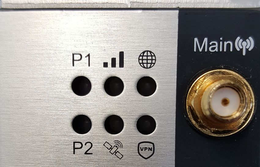
Preface

Preface
Audience
This guide is for the network or computer technician responsible for installing the Perle IRG5140+
router also generically referred to as the IRG5140 within this document. All “+” models support
worldwide global coverage for LTE. Familiarity with the concepts and terminology of LTE, GNSS,
Ethernet, and LAN (local area networks) are required.

Purpose
Perle routers provide users, networking equipment, as well as M2M & IoT appliances with network
connectivity for fixed locations (i.e. buildings, POS, Kiosks, …etc.) and mobile (i.e. vehicle, trains,
robots) applications. In vehicular applications, the router provides connectivity and does not interact
with the vehicle’s operation or vehicle operators.
This document describes the hardware and physical characteristics of the Perle IRG5140 Series of
Routers. It covers hardware features as well as installation and operation. This document does not
cover how to configure your Perle IRG 5140 router. Information to configure your Perle router can be
found in the Perle IRG5000 Series Router User’s Guide and the Perle IRG5000 Series Router CLI
Reference Guide on the Perle website. Quick Start information can be found in the IRG5140 Cellular
LTE Router Quick Start Guide (QSG) that comes with your product.

Key Features
      •   Supports bridging/switching and routing
      •   LTE coverage spanning
      •   LTE coverage spanning 30 frequency bands for global coverage
      •   Fully automatic network switching supporting dual network SIMs
      •   Routing with Primary/Backup route
      •   LTE and VPN Fail-over
      •   Provides network connectivity via LTE, Ethernet and USB-C
      •   Active GPS for tracking equipment
      •   Security via remote authentication (RADIUS and TACACS+)
      •   Meets industry-grade certifications

                        Perle IRG5140+ Series Router Hardware Installation Guide                          I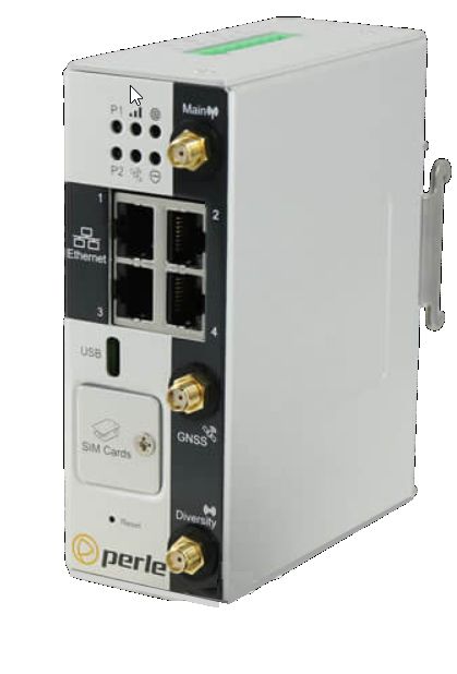
Preface

Additional Documentation
 Document                              Description
Perle IRG5000 Series Router User’s     User guide explaining how to configure the IRG 5140
Guide                                  features using the Web Manager application. New users
                                       should use this method to configure the router.
Perle IRG5000 Series Router CLI        Command Line Interface Reference Guide using CLI
Reference Guide                        commands to configure the IRG 5140 (this is an
                                       advanced way to configure the router).

                     Perle IRG5140+ Series Router Hardware Installation Guide                   II
Preface

Document Conventions
This document contains the following conventions:

Most text is presented in the typeface used in this paragraph. Other typefaces are used to help you
identify certain types of information. The other typefaces are:

Note: Means reader take note: notes contain helpful suggestions.

Caution: Means reader be careful. In this situation, you might perform an action that could result in
equipment damage or loss of data.
Warning: IMPORTANT SAFETY INSTRUCTIONS
Means danger. You are in a situation that could cause bodily injury. Before you work on any equipment, be
aware of the hazards involved with electrical circuitry and be familiar with standard practices for preventing
accidents.
Important Notice
Due to the nature of wireless communications, transmission and reception of data can never be
guaranteed. Data may be delayed, corrupted (i.e., have errors) or be totally lost. Although significant
delays or losses of data are rare when cellular devices such as the Perle IRG5140 Series Routers are
used in a normal manner with a well-constructed network. The Perle IRG5140 Series Routers should
not be used in situations where failure to transmit or receive data could result in damage of any kind
to the user or any other party, including but not limited to personal injury, death, or loss of property.
Perle accepts no responsibility for damages of any kind resulting from delays or errors in data trans-
mitted or received using our products.
Safety and Hazards
The driver or operator of any vehicle should not operate the IRG5140 while in control of a vehicle.
Doing so will detract from the driver or operator's control and operation of that vehicle. The IRG5140
is Listed to UL121201 and CSA C22.2 No. 213 and are suitable for use in Class I, Division 2, Groups
A, B, C and D Hazardous Locations.

The following warnings and instructions apply:
Limitation of Liability
The information in this manual is subject to change without notice and does not represent a commit-
ment on the part of Perle for any and all direct, indirect, special, general, incidental, consequential,
punitive or exemplary damages including, but not limited to loss of profits or revenue or anticipated
profits or revenue arising out of the use or inability to use any Perle IRG 5140 series router even if
Perle has been advised or the possibility of such damages or they are
foreseeable or for claims by any third party.
Notwithstanding the foregoing, in no event shall Perle aggregate liability arising under or in connec-
tion with the Perle product, regardless of the number of events, occurrences, or claims giving rise to
liability, be in excess of the price paid by the purchaser for the Perle
product.

Copyright © 2021 Perle. All rights reserved.
Windows® is a registered trademarks of Microsoft Corporation.
Other trademarks are the property of their respective owners

                          Perle IRG5140+ Series Router Hardware Installation Guide                               III
Preface
General cautions and warnings
13
IEC 60417-5041 (2002-10) Caution, hot surface
14 Refer to manual/safety
Warning: Power sources must be off prior to beginning the power connection steps. Read the
installation instructions before you connect the unit to its power source.
Avertissement: Les sources d'alimentation doivent être éteintes avant de commencer les étapes de
connexion d'alimentation. Veuillez lire les instructions d’installation avant de connecter l’appareil à
sa source d’alimentation.
Warning: Ensure that the voltage and current ratings of the intended power source are appropriate for
the IRG5140 Series of Routers as indicated on the product label.
Avertissement: Assurez-vous que les valeurs nominales de tension et de courant de la source d'ali-
mentation prévue conviennent aux routeurs de la série IRG5140, comme indiqué sur l'étiquette du
produit.
Warning: Ensure that the installation and electrical wiring of the equipment is performed by trained
and qualified personnel and that the installation complies with all local and national electrical codes.
Avertissement: Assurez-vous que l'installation et le câblage électrique de l'équipement sont effectués
par du personnel formé et qualifié et que l'installation est conforme à tous les codes électriques locaux
et nationaux.
Warning: This equipment must be used in the matter specified by the manufacturer.
Avertissement: Cet équipement doit être utilisé dans les matières spécifiées par le fabricant.
Warning: In case of malfunction or damage, no attempts at repair should be made by the user. Do not
dismantle this product. In case of malfunction or damage, contact Perle Technical support at
https://www.perle.com/support_services/support_request.aspx
or email at
https://www.perle.com/support_services/support_request.aspx#form
Avertissement: En cas de dysfonctionnement ou de détérioration, aucune tentative de réparation ne
doit être effectuée par l'utilisateur. Ne démontez pas ce produit. En cas de dysfonctionnement ou de
dommage, contactez le support technique de Perle à l'adresse
https://www.perle.com/support_services/support_request.aspx
ou par courrier électronique à
https://www.perle.com/support_services/support_request.aspx#form
Warning: If the ambient temperature is to exceed 50°C (122°F), the unit should be installed in a
restricted access location where access can only be gained by service personnel or users who have
been instructed about the reasons for the restrictions applied to the location and about any precautions
Perle IRG5140+ Series Router Hardware Installation Guide IVPreface
that shall be taken; and access is through the use of a tool or lock and key, or any means of security,
and is controlled by the authority responsible for the location.
Avertissement: Si la température ambiante doit dépasser 50 ° C, l'unité doit être installée dans un
emplacement à accès restreint, auquel seul le personnel de service ou les utilisateurs informés des rai-
sons des restrictions appliquées peuvent accéder. sur le lieu et sur les précautions à prendre; et l'accès
se fait au moyen d'un outil ou d'un verrou et d'une clé, ou de tout moyen de sécurité, et est contrôlé
par l'autorité responsable du lieu.
Warning: The working voltage inputs are designed for operation with Safety extra low Voltage
(SELV). Connect only to SELV circuits with voltage restrictions in line with IEC/EN 62368-1.
Avertissement: Les entrées de tension sont conçues pour fonctionner avec une tension de sécurité
très basse (SELV). Connectez uniquement aux circuits SELV avec des restrictions de tension con-
formes à IEC / EN 62368-1.
Warning: For equipment installed within the same end-product enclosure ensure leads are segregated
or insulated the leads from different circuits.
Avertissement: Pour les équipements installés dans le même boîtier de produit final, assurez-vous
que les conducteurs sont séparés ou isolés des conducteurs de circuits différents.
Hazardous Location Warnings
Specific Conditions of Use
1. The IRG5140+ Routers are intended for installation into an IECEx/ATEX certified and IP54
minimum rated enclosure in accordance with IEC/EN 60079-0 and accessible only by the use of a
tool. Les modèles de routeurs IRG5140+ sont destinés à être installés dans un boîtier certifié
IECEx/ATEX qui conforme à la norme IP54 conformément à la norme IEC/EN 60079-0 et
accessible uniquement à l'aide d'un outil.
2. The equipment shall only be used in an area of not more than pollution degree 2, as defined in
IEC/EN 60664-1. L'équipement ne doit être utilisé que dans une zone où le degré de pollution n'est
pas supérieur à 2, tel que défini dans la IEC/EN 60664-1.
Warning: These devices are open-type devices that are to be installed in an enclosure with tool
removable cover or door, suitable for the environment.
Avertissement: Ces périphériques sont des périphériques de type ouvert à installer dans un boîtier
avec un couvercle ou une porte amovible pour outils, adapté à l'environnement.
Warning: This equipment is suitable for use in Class I, Division 2, Groups A, B, C, D, or only non
hazardous locations.
Avertissement: Cet équipement est adapté à une utilisation dans les zones non dangereuses de classe
I, division 2, groupes A, B, C, D
Warning: WARNING-EXPLOSION HAZARD - Do not connect or disconnect equipment unless
power has been removed or the area is known to be non-hazardous.
Avertissement: DANGER D'EXPLOSION ET D'AVERTISSEMENT - Ne pas connecter ou decon-
necter l'équipement tant que l'alimentation n'est pas débranchée ou que la zone n'est pas dangereuse.
Perle IRG5140+ Series Router Hardware Installation Guide VPreface
Warning: WARNING-EXPLOSION HAZARD - Substitution of any components on this unit may
impair suitability for Class I, Division 2.
Avertissement: DANGER DANGER D’EXPLOSION - La substitution de tout composant de cet
appareil peut compromettre l’adéquation à la Classe I, Division 2.
Warning: Power supply of the equipment must be rated appropriately (see Appendix for specifica-
tions) with limited power. Limited power means complying with one of the following requirements.
Class 2 circuit according to Canadian Electrical Code, Part 1, C22.1
Class 2 circuit according to National Electrical Code, NFPA-70
Limited Power Supply (LPS) according to EN/IEC 60950-1;
Limited-energy circuit according to EN/IEC 61010-1
Avertissement: l'alimentation de l'équipement doit être correctement dimensionnée (voir annexe
pour les spécifications) avec une puissance limitée. Une puissance limitée signifie que vous vous con-
formez à l'une des exigences suivantes.
Circuit de classe 2 selon le code électrique Canadien, partie 1, C22.1
Circuit de classe 2 selon le code électrique national NFPA-70
Alimentation électrique limitée (LPS) selon EN / IEC 60950-1;
Circuit à énergie limitée selon EN / IEC 61010-1
Warning: If this equipment is used in a manner not specified by the manufacturer, the protection
provided by the equipment may be impaired.
Avertissement: Si cet équipement est utilisé d'une manière non spécifiée par le fabricant, la protec-
tion fournie par l'équipement peut être altérée.
Warning: In case of malfunction or damage, no attempts at repair should be made. Do not dismantle
the product. All repairs need to be made by a qualified Perle representative. Contact Perle Systems
Technical support at https://www.perle.com/support_services/support_request.aspx or email at
https://www.perle.com/support_services/support_request.aspx#form
Avertissement: En cas de dysfonctionnement ou de dommage, aucune tentative de réparation ne doit
être effectuée. Ne démontez pas le produit. Toutes les réparations doivent être effectuées par un
représentant qualifié de Perle. Contactez le support technique de Perle Systems à l'adresse
https://www.perle.com/support_services/support_request.aspx ou par courrier électronique à
https://www.perle.com/support_services/support_request.aspx#form
Warning: This router is not intended for use close to the human body. The unit should be mounted in
such that Antennas are at least 20cm (8 inches) away from any person.
Avertissement: Ce routeur n’est pas destiné à être utilisé à proximité du corps humain. L’appareil
devrait être monté de façon à ce que les antennes soient à au moins 20 cm (8 po) de toute personne.
Warning: Explosion hazard. Do not connect or disconnect while the circuit is live or unless the area
is free of ignitable concentrations.
Avertissement: Risque d'explosion. Ne pas connecter ou deconnecter le circuit est sous tension ou à
moins que la zone ne présente aucune concentration inflammable.
Warning: Do not use the USB connector unless the area is free of ignitable concentrations.
Avertissement: N'utilisez pas le connecteur USB à moins que la zone ne soit exempte de
Perle IRG5140+ Series Router Hardware Installation Guide VIPreface
concentrations inflammables.
Warning: Do not use the reset button unless the area is free of ignitable concentrations.
Avertissement: N'utilisez pas le bouton de réinitialisation à moins que la zone ne soit exempte de
concentrations inflammables.
RF Exposure
In accordance with FCC/IC requirements of human exposure to radio frequency fields, the radiating
element shall be installed such that a minimum separation distance of 20 cm should be maintained
from the antenna and the user's body.
Conformément aux exigences de la FCC/IC relatives à l’exposition humaine aux champs de
radiofréquences, l’élément de rayonnement doit être installé de manière à ce qu’une distance de
séparation minimale de 20 cm soit maintenue par rapport à l’antenne et au corps de l’utilisateur.
THE SPECIFICATIONS AND INFORMATION REGARDING THE PRODUCTS IN THIS
GUIDE ARE SUBJECT TO CHANGE WITHOUT NOTICE. ALL STATEMENTS,
INFORMATION, AND RECOMMENDATIONS IN THIS GUIDE ARE BELIEVED TO BE
ACCURATE BUT ARE PRESENTED WITHOUT WARRANTY OF ANY KIND, EXPRESS OR
IMPLIED. USERS MUST TAKE FULL RESPONSIBILITY FOR THEIR APPLICATION OF
ANY PRODUCTS.
This equipment has been tested and found to comply with the limits for a Class B digital device, pursuant to
part 15 of the FCC rules. These limits are designed to provide reasonable protection against harmful
interference when the equipment is operated in a commercial environment. This equipment generates, uses,
and can radiate radio-frequency energy and, if not installed and used in accordance with this hardware guide
may cause harmful interference to radio communications.
Modifications to this product not authorized by Perle could void the FCC approval and negate your authority to
operate the product.
Perle reserves the right to make changes without further notice, to any products to improve reliability, function,
or design.
Perle, the Perle logo, and IRG5140+ Series of Routers are trademarks of Perle.
Copyright ©2021 Perle.
60 Renfrew Drive, Markham, Ontario, L3R 0E1, Canada
All rights reserved. No part of this document may be reproduced or used in any form without written permission
from Perle.
Perle IRG5140+ Series Router Hardware Installation Guide VIIPreface
Publishing History
Date Revision Update Details
March 2020 A.03.23.2020 Initial release.
Dec 2020 A.12.31.2020 Updates to LED tables.
April 2021 A.04.26.2021 Update to Factory default table
June 2021 A.06.03.2021 Update to label
Perle IRG5140+ Series Router Hardware Installation Guide VIIITable Of Contents Preface . . . . . . . . . . . . . . . . . . . . . . . . . . . . . . . . . . . . . . . . . . . . . . . . . . . . . . . . . . . . . . . I Overview . . . . . . . . . . . . . . . . . . . . . . . . . . . . . . . . . . . . . . . . . . . . . . . . . . . . . . . . . . . . . 1 What’s Included . . . . . . . . . . . . . . . . . . . . . . . . . . . . . . . . . . . . . . . . . . . . . . . . . . . . . . 1 What You Need to Supply . . . . . . . . . . . . . . . . . . . . . . . . . . . . . . . . . . . . . . . . . . . . . . 1 Hardware . . . . . . . . . . . . . . . . . . . . . . . . . . . . . . . . . . . . . . . . . . . . . . . . . . . . . . . . . . . . 2 Front View . . . . . . . . . . . . . . . . . . . . . . . . . . . . . . . . . . . . . . . . . . . . . . . . . . . . . . . . . . 2 LEDs . . . . . . . . . . . . . . . . . . . . . . . . . . . . . . . . . . . . . . . . . . . . . . . . . . . . . . . . . . . . . . 2 SIM Card/s . . . . . . . . . . . . . . . . . . . . . . . . . . . . . . . . . . . . . . . . . . . . . . . . . . . . . . . . . . 6 Antenna/s . . . . . . . . . . . . . . . . . . . . . . . . . . . . . . . . . . . . . . . . . . . . . . . . . . . . . . . . . . . 6 USB-C Port . . . . . . . . . . . . . . . . . . . . . . . . . . . . . . . . . . . . . . . . . . . . . . . . . . . . . . . . . 6 Ethernet LAN Ports . . . . . . . . . . . . . . . . . . . . . . . . . . . . . . . . . . . . . . . . . . . . . . . . . . . 7 Ethernet Link Status . . . . . . . . . . . . . . . . . . . . . . . . . . . . . . . . . . . . . . . . . . . . . . . . . . . 7 GNSS Connector . . . . . . . . . . . . . . . . . . . . . . . . . . . . . . . . . . . . . . . . . . . . . . . . . . . . . 7 Terminal Block-Power Connector . . . . . . . . . . . . . . . . . . . . . . . . . . . . . . . . . . . . . . . . 8 Installation . . . . . . . . . . . . . . . . . . . . . . . . . . . . . . . . . . . . . . . . . . . . . . . . . . . . . . . . . . . 8 Inserting the SIM card . . . . . . . . . . . . . . . . . . . . . . . . . . . . . . . . . . . . . . . . . . . . . . . . . 8 Connecting the Antenna/s . . . . . . . . . . . . . . . . . . . . . . . . . . . . . . . . . . . . . . . . . . . . . . 9 Connecting to the Ethernet Ports/s. . . . . . . . . . . . . . . . . . . . . . . . . . . . . . . . . . . . . . . . 9 Connecting to the USB-C port in Console Mode. . . . . . . . . . . . . . . . . . . . . . . . . . . . 10 Connecting to the USB-C port as an Ethernet over USB Port . . . . . . . . . . . . . . . . . . 10 Connecting the Power . . . . . . . . . . . . . . . . . . . . . . . . . . . . . . . . . . . . . . . . . . . . . . . . 11 Operation . . . . . . . . . . . . . . . . . . . . . . . . . . . . . . . . . . . . . . . . . . . . . . . . . . . . . . . . . . . 12 Reset / Factory Default / Safe Mode . . . . . . . . . . . . . . . . . . . . . . . . . . . . . . . . . . . . . 12 Reset Button . . . . . . . . . . . . . . . . . . . . . . . . . . . . . . . . . . . . . . . . . . . . . . . . . . . . . . . . 12 Fast Setup . . . . . . . . . . . . . . . . . . . . . . . . . . . . . . . . . . . . . . . . . . . . . . . . . . . . . . . . . . . 13 Managing the IRG5140+ . . . . . . . . . . . . . . . . . . . . . . . . . . . . . . . . . . . . . . . . . . . . . . . 14 WebManager . . . . . . . . . . . . . . . . . . . . . . . . . . . . . . . . . . . . . . . . . . . . . . . . . . . . . . . 14 CLI . . . . . . . . . . . . . . . . . . . . . . . . . . . . . . . . . . . . . . . . . . . . . . . . . . . . . . . . . . . . . . . 14 SNMP. . . . . . . . . . . . . . . . . . . . . . . . . . . . . . . . . . . . . . . . . . . . . . . . . . . . . . . . . . . . . 14 Fast Setup Mode. . . . . . . . . . . . . . . . . . . . . . . . . . . . . . . . . . . . . . . . . . . . . . . . . . . . . 14 PerleView. . . . . . . . . . . . . . . . . . . . . . . . . . . . . . . . . . . . . . . . . . . . . . . . . . . . . . . . . . 14 I/O Configurations . . . . . . . . . . . . . . . . . . . . . . . . . . . . . . . . . . . . . . . . . . . . . . . . . . . . 15 Pulse Counter / Digital Input . . . . . . . . . . . . . . . . . . . . . . . . . . . . . . . . . . . . . . . . . . . 15 Relay . . . . . . . . . . . . . . . . . . . . . . . . . . . . . . . . . . . . . . . . . . . . . . . . . . . . . . . . . . . . . 15 Appendix A—Technical Specifications . . . . . . . . . . . . . . . . . . . . . . . . . . . . . . . . . . . 16 Appendix B—Sample Labels . . . . . . . . . . . . . . . . . . . . . . . . . . . . . . . . . . . . . . . . . . . 20 Appendix C—Mounting the Router . . . . . . . . . . . . . . . . . . . . . . . . . . . . . . . . . . . . . . 21 Appendix D—Mechanical . . . . . . . . . . . . . . . . . . . . . . . . . . . . . . . . . . . . . . . . . . . . . . 22 Appendix E—Maintaining and Troubleshooting . . . . . . . . . . . . . . . . . . . . . . . . . . . 23
Overview

Overview
The IRG5140+ router is a compact, rugged, fully featured communications platform for real-time
wireless capabilities. It has multiple communication ports including Ethernet, and a USB port that can
be used as a console port or as an additional Ethernet port. It supports LTE/4G wireless solutions for
both fixed and mobile applications (IoT). The LTE/4G supports Cat-12 technology with peak down-
load rates of 600 Mbps and uploads speeds of 150 Mbps. The IRG5140+ includes integrated GNSS
receiver (GPS, GLONASS, Beidou, and Galileo) satellite support.

Application uses:
      • Remotely monitoring and controlling equipment on pipelines, meters, pumps and valves in
        any energy, utility, or industrial application
      • Tracking the location of heavy equipment and assets in the field
      • Providing reliable Internet access to a mobile workforce
What’s Included
The following components may be included with your product. Components will vary depending for
each model. See the Perle website for updates.
      • The router
      • Quick Start Guide
      • 2 LTE SMA antenna pack (#08000120)
      • GNSS PASV RP-Antenna SMA/CA (#08000130) passive or active antenna (order-able from
         Perle #08000130)
What You Need to Supply
Before you can begin, you need to have the following:
     • A SIM card/s (provided by your mobile network operator)
     • #1 Phillips screwdriver (if you are installing the SIM card)
     • Computer or laptop computer with Ethernet interface and cable
     • An Ethernet CAT5e or CAT6 10/100/1000BASE-T cable/to connect the
        router to the network

                        Perle IRG5140+ Series Router Hardware Installation Guide                      1
Hardware
Hardware
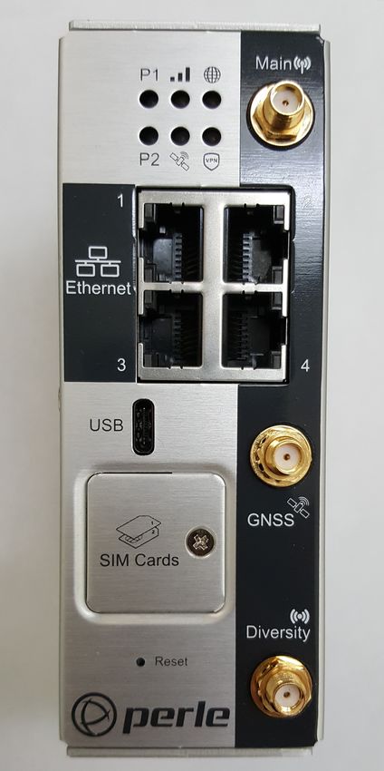
Front View
LEDs
Power LED Function Normal Low Power Meaning
(P1 and P2) Mode Power must be applied
to the Power inputs P1
and P2 in order for the
LEDs to light.
No Power Off N/A
Boot Red—solid N/A
Green— Blip N/A N/A
Powering up Amber—flashing N/A
Perle IRG5140+ Series Router Hardware Installation Guide 2Hardware
Normal Green—solid Green—blip
Operation starting after a
boot is
complete
Normal Green—flashing
operation but
no config
Fatal error Red—solid Red—solid
Setup Mode Amber—solid Amber—solid When you press and
hold the reset button
for 15 seconds during
operational mode. The
solid amber LED
indicate the time to
release to initiate
setup mode.
Factory Reset Red—solid Red—solid Press and hold the
reset button for 20
seconds during power
up. The solid red LED
indicates the time to
release for reset to
factory.
Overheat Red—blip Red—blip Overheat causes the
Standby unit to go into Standby
mode. The router will
restart when the
temperature is below
the temperature
threshold.
No Config Green—flashing N/A Unit is powered up
normally—unit has no
config. Unit is in Safe
mode or Factory
default mode.
WWAN Function Normal Low Power Meaning
Mode
Disabled Off Off
Perle IRG5140+ Series Router Hardware Installation Guide 3Hardware
Connected— Color—solid Off—once Colour will depend on
good signal connection is signal strength.
established, it Green = Good signal—
will come on >= -80dBm
for 5 secs then Amber = Fair signal—
go off >-94dBmHardware
Internet Function Normal Low Power Meaning
Mode
Disconnected Off Off No connection by
intention
disabled or radio
off
disconnect
requested
Connected Green—solid Off LTE primary if no
WAN
Primary connection
if WAN
Backup mode Amber—solid Off Backup connection if
WAN.
Connection Red—solid Red—blip A connection was
failure attempted, but it
failed.
APN incorrect
SIM card missing
insufficient signal
no service
modem failure
data connection
failed—waiting to
retry
PIN incorrect SIM
blocked, bad
unlock code
SIM locked
SIM blocked,
unblock code
incorrect
Perle IRG5140+ Series Router Hardware Installation Guide 5Hardware
SIM Card/s
The IRG5140+ supports two SIM cards. See Inserting the SIM card for the installation procedure.
SIM/s Interface 1.8V/3V
Antenna/s
The router has three SMA antenna connectors Main, Diversity and GNSS. For more information on
connecting the antennas see Antenna/s.
USB-C Port
In console mode, the router’s 5140+ USB port provides direct access to the Command Line Interface
(CLI) as well as provides statuses, logging, and troubleshooting information. Alternative, this port
can be set as an Ethernet over USB port.
See Connecting to the USB-C port in Console Mode and Connecting to the USB-C port as an Ether-
net over USB Port.
Perle IRG5140+ Series Router Hardware Installation Guide 6Hardware
Ethernet LAN Ports
Once the ports are connected and the link is established, the speed LED will turn on. The LED
indicates a 10, 100, or 1000 Mbps link on the Ethernet port/s
Ethernet Link Status
Link/Speed Indicator Description
Left LED Green Link + Flashing with activity 1000 Mbps
Both LEDs Link + Flashing with activity 100 Mbps
Right LED Green Link + Flashing with activity 10 Mbps
Off Off No LAN connected
GNSS Connector
GPS+GLONAS+GAILEO
Passive Antenna—SMA(M) straight connector
See GNSS Technical Specifications for electrical details.
Perle IRG5140+ Series Router Hardware Installation Guide 7Installation
Terminal Block-Power Connector
The power plug has two power connections, one relay connection and one digital input connection.
For details on wiring up these connection see Connecting the Power
Installation
The steps for a typical installation are:
1. Inserting the SIM card/s. See Inserting the SIM card.
2. Connecting the antenna/s. See Connecting the Antenna/s.
3. Connecting the Ethernet Ports. See Ethernet LAN Ports.
4. Connecting to the Console Port in Console Mode. See Fast Setup Mode or Connecting to the
USB-C port in Console Mode.
5. Using the Console port as a virtual Ethernet port. See Connecting to the USB-C port as an Ether-
net over USB Port.
6. Connecting the power. See Connecting the Power.
7. Logging into the IRG5140+. See Fast Setup or Connecting to the USB-C port in Console Mode.
Inserting the SIM card
The IRG5140+ comes with two SIM sockets for mini-SIM (2FF) cards.
Note: Ensure the power is disconnected before you insert the SIM card/s.
1. Using your Phillips screwdriver, removed the screw from the panel covering the SIM slots. Gen-
tly pry the cover loose from the opening.
2. Align the SIM card so that the SIM card will slide into the top slot (slot#1). Each SIM card has a
notched corner for orientation and the SIM card can only be inserted the correct way. You will
hear an audible click when the SIM is inserted correctly. Always populate slot#1 first. Add a
second SIM card if your network setup requires it.
3. Align the SIM cover plate and secure the plate with the screw.
Note: Do not force the SIM(s) card in or you may damage the card or your IRG5140+ router.
Perle IRG5140+ Series Router Hardware Installation Guide 8Installation
Connecting the Antenna/s
The router has these connectors:
• Main Cellular female antenna connector
• Rx Diversity female antenna connector
• GNSS female antenna connector
1. Connect your cellular antenna to the SMA cellular antenna connector labeled Main.
2. Connect your GPS antenna to the SMA GPS antenna connector labeled GNSS.
3. Mount the GPS antenna where it has a good view of the sky (at least 90⁰).
4. Connect the diversity antenna to the SMA diversity antenna labeled Diversity.
Warning: For Zone 2 and/or Class I, Division 2 hazardous location applications. Antennas intended for use with
the product must be installed within the end use enclosure. For remote mounting of the antennas in unclassified
or classified locations, routing and installation of the antennas shall be in accordance with the appropriate
location regulations.
Note: When attaching the antennas to the SMA connectors hand tighten only (do not use tools to tighten
(maximum torque is 7Kgf-cm/1.1 N-m(10 in-lb).
Connecting to the Ethernet Ports/s
The Ethernet RJ45 ports provides the standard Ethernet interface speeds of 10/100/1000 Mbps through
twisted pair (UTP) cables of up to 100 meters (328ft) in length. Cat5e or Cat6 cables are
recommended for 1000 Mbps connections.
Female Serial Pin out
Name Pin Description Type
DCD 1 Data Carrier Detect OUT
TXD 2 Transmit Data OUT
RXD 3 Receive Data IN
Perle IRG5140+ Series Router Hardware Installation Guide 9Installation
DTR 4 Data Terminal Ready IN
GND 5 Ground GND
DSR 6 Data Set Ready OUT
RTS 7 Request to Send IN
CTS 8 Clear to Send OUT
RI 9 Not Connected -
Connecting to the USB-C port in Console Mode
By default, the USB-C port is set to console mode. In this mode, the USB-C port acts as a console
port.
1. Connect the power. See Connecting the Power.
2. Allow the router to complete the boot up sequence.
3. Connect a USB cable to the PC’s USB port, then connect the other end of the cable to the router’s
USB-C connector.
4. On the PC Choose Start -> Control Panel -> Hardware and Sound (or equivalent) on the Windows
Operating System. Choose the Device Manager, and expand the Ports section. The assigned COM
port can be identified.
5. Start a terminal emulation program (such as Putty or SecureCRT) on the com port where you have
connected the cable to the PC.
6. Press the Enter key on the keyboard and the prompt displays.
See the Perle IRG5000 Series Router CLI Reference Guide for more information on using CLI
commands.
Warning: If you connect or disconnect the console cable with the power applied to the router or any device on the
network, an electrical arc can occur. This could cause an explosion when installed in a hazardous location. Ensure
the power is removed from all devices prior to making any cable connections.
Warning: Do not use the USB port in a potentially explosive environment.
Connecting to the USB-C port as an Ethernet over USB Port
In this mode, the USB-C port behaves as if a PC is connected to the Ethernet port, allowing access to
networks and the Internet.
See the Perle IRG5000 Series Router User’s Guide and the Perle IRG5000 Series Router CLI Refer-
ence Guide for more information on setting this parameter.
Perle IRG5140+ Series Router Hardware Installation Guide 10Installation
Connecting the Power
The power connector can be found at the top of the router. The connector can be removed from the
unit for easy insertion of wires. Once all wires have been secured to the power connector, the connec-
tor can be re-inserted into the top of the router.
The connector includes the following items.
P1–Primary power connection
P2–Secondary power connection
R–Relay connection
IN–Digital Input connection
A “Grounding Lug” is available if your installation requires additional grounding.
The IRG5140+ Router has two power inputs that can be connected simultaneously to provide redun-
dant power. If one power source fails, the other source acts as a backup and powers the Router.
Note: Wiring with suitable temperature ratings must be used. Refer to specification section for details.
Use copper wire only if the terminal is only for connection to copper wire.
1. Ensure the power source is off prior to connection
2. Strip both (18-22AWG) wires 7 mm
3. Loosen the terminal block screws and connect positive (+) / negative (-) wires into the +/- termi-
nals
4. Tighten terminal screws (0.5 - 0.6 Nm torque). Ensure the wires are securely fastened.
5. Re-insert the Terminal Block connector if removed, Turn on power source. Check LED indicators
in the guide for power status
6. Connect P2 (power source 2, beginning at Step 1)
7. Ensure that there is one individual conductor for each clamping point.
If you are using a cable that is longer than two meters, we recommend the following:
Wire gages (AWG):
• 22 gauge wire or up to 4 meters (13ft)
• 20 gauge wire for up to 6 meters (20ft)
• 18 gauge wire for up to 12 meters (40ft)
Cable and connector must be rated for minimum 76°C (168.8°F)
Note: Before servicing this product ensure the power source has been disconnected. Electrical
installations should be performed by personnel thoroughly trained in safe electrical wiring
procedures.
Perle IRG5140+ Series Router Hardware Installation Guide 11Operation
Operation
Reset / Factory Default / Safe Mode
The table below shows how the reset button is used.
Reset Button
Mode Description LEDs System Status
Restart Press and release the Power LED will Reboots. All configuration and
Reset button when the begin to blink files remain the same.
router is running Amber
Factory Press the Reset button LEDs flash Red Reboots and resets the
Default and Hold for about 20 configuration to the Perle
seconds when the router factory default configuration.
is running All configuration, User IDs,
passwords, and security
certificates are deleted.
Safe Mode Press the Reset button All LEDs, except Saves the startup config
while powering up Power blinking Boots with no config file
Amber Allows you to do setup
mode
Perle IRG5140+ Series Router Hardware Installation Guide 12Fast Setup
Fast Setup
Fast Setup mode allows you to quickly configure basic operating parameters on your router.
Your Perle router is shipped to you in Factory Default mode. On power up, your router is in “Fast
Setup” mode with the Power LED flashing green. Make a connection to your router via the console
port or a Web browser, then answer basic setup operating parameters such as your initial user ID and
password. To connect to the console port, follow the instructions provided in—Connecting to the
USB-C port in Console Mode.
To connect using a Web browser, connect your PC’s Ethernet cable directly to an Ethernet port on the
router. Configure the PC to use DHCP for obtaining its IP address. The router will act as a DHCP
server and assign an IP address to the PC. Next, launch the Web browser and browse to
“http://192.168.0.1”. The Fast Setup screen appears.
Refer to the Quick Start Guide or the Perle IRG5000 Series Router User’s Guide for more informa-
tion on setup instructions.
Perle IRG5140+ Series Router Hardware Installation Guide 13Managing the IRG5140+
Managing the IRG5140+
The IRG5140+ can be configured, operated, and monitored using any of the following methods. See
the Perle IRG5000 Series Router User’s Guide for more details on these methods.
WebManager
The Perle WebManager—an embedded Web based application provides an easy to use browser inter-
face for configuring and managing the IRG5140+. The WebManager is accessible through any stan-
dard desktop web browser. Configured a valid IP address on the IRG5140+ before connecting with
the WebManager.
CLI
A text-based Command Line Interface based on industry standard syntax and structure. The CLI is
accessed from the console port. Once a valid IP address is configured on the IRG5140+, you can use
Telnet or SSH to access the IRG5140+ for administration purposes. See the Perle IRG5000 Series
Router CLI Reference Guide for more information.
SNMP
The IRG5140+ can be managed with an SNMP compatible management station that is running plat-
forms such as HP Openview.
Fast Setup Mode
If your router is in “Factory Default” mode, when you first connect, you are in “Fast setup mode”.
For more details, see—Fast Setup.
PerleView
A Windows server-based centralized management package that simplifies the configuration, adminis-
tration, monitoring, and troubleshooting of Perle Managed Media Converters, Ethernet Copper
Extenders, Industrial Switches, IRG Series of Perle Routers and other Perle products. Your Internet
browser can securely access PerleVIEW and manage 10’s, 100’s or 1000’s of Perle devices from a
centralized server.
Perle IRG5140+ Series Router Hardware Installation Guide 14I/O Configurations
I/O Configurations
• GPIO can be used as a Pulse counter
• Digital input
Pulse Counter / Digital Input
You can connect as:
• a pulse counter to monitor frequencies up to 512 Hz, with duty cycle between 25%–75%
• a digital input to detect the state of a switch
• a monitor to an external device such as a motion detector, a remote solar panel, or a remote
camera.
Input Range State
0 - 1V Low
2.7 - 36V High
Relay
Pins 5 and 6 of the power connector can be connected to an external circuit which will be controlled
by the internal relay. When the relay is engaged, the external circuit will be completed. The relay is a
Normally Open (NO) relay.
The relay is rated at a maximum of 1A@24VDC
Perle IRG5140+ Series Router Hardware Installation Guide 15Appendix A—Technical Specifications
Technical Specifications
General
Power Requirements Input: 9.6-60VDC, 1000 mA max
Power Line Protection Fast transients 1.5KV (ENG61000-4-4 Criteria B)
Surge 2KV (EN61000-4-5 common mode), 1.5KV (EN61000-4-
5 differential and common modes)
Power Built-in protection against voltage transient including 5 VDC
engine cranking and +200 VDC load dump
SAE J1455, MIL-STD-810G
Interfaces
Ethernet Port 4 Ethernet 10/100/1000 Auto-neg
Isolation 1.5 kV
IEEE 802.3 for 10Base-T
IEEE 802.3u for 100Base-TX and 100Base-FX
IEEE 802.3ab for 1000Base-T
IEEE 802.3x for Flow Control
USB 1
Type USB 3.0 Type-C
Can be used as a console or additional Ethernet port.
SIM 2
15*25mm (2FF)
Environmental Specifications
Operating Temperature Ranges -40°C to 70°C (40°F to 158°F)
Storage Temperature -40°C to 85°C (40°F to 185°F)
Operating Humidity Ranges 0% to 95% non-condensing
Storage Humidity Ranges 0% to 95% non-condensing
Operating Altitude Up to 3,048 meters (10,000 feet)
MTBF 287,215 hours
Standards and Certifications
Safety UL/ULC/EN 62368-1 (previously 60950-1)
CE Mark
CAN/CSA-C22.2 No. 62368-1-14
UL 61010-1 and 61010-2-201
Perle IRG5140+ Series Router Hardware Installation Guide 16Technical Specifications
EMI/EMC FCC 47 Part 15, Subpart B, Class B
ICES-003 Issue 6 Class B (Canada)
EN302489 (Vehicle Installation)
CISPR 32:2015/EN 55032:2015 (Class A)
CISPR 25:2016/EN 55025
CISPR 24:2010/EN 55024:2010
CISPR 35:2016/EN 55035:2017
EN 61000-3-2 Limits for Harmonic Current Emissions
EN 61000-3-3 Limits of Voltage Fluctuations and Flicker
EN 61000-4-2 (ESD): Contact:
EN 61000-4-3 (RS):
EN 61000-4-4 (EFT):
EN 61000-4-5 (Surge):
EN 61000-4-6 (CS):
EN 61000-4-8 (PFMF):
EN 61000-4-11
EN 61000-4-16
EN 61000-6-4:2007 +A1:2011
ISO 7637-2:2004
Hazloc ATEX Class 1 Zone 2
ANSI/ISA 12.12.01, Class 1 Division2, Group A, B, C, D
IECEx UL 21.0069X
Railway EN 50155:2017 Clause 4.3.6
EN 50121-1:2017, 50121-3-2:2016, 50121-4:2016
IEC 60571:2012 for Clause 12.2.8 and 12.2.9
IEC 62236-1:2018. 62236-3-2:2008, 62236-4:2018
Cellular certifications PTCRB, RED
Environment Testing
Shock and Vibration SAE J1455 (Shock and Vibration)
MIL-STD-810G
EN 61373
IP rating Complaint to IP64
Drop ISTA 2A 2001, test categorizes 1, 4,5, and 6
Power connector
Digital input and pulse counting Digital Input & Pulse Counting VDC: 0 for ≤ 1V, 1 for ≥ 2.7
Perle IRG5140+ Series Router Hardware Installation Guide 17Technical Specifications
Relay Normally Open (NO) dry contact 1A@24VDC
GNSS
Frequency range GNSS: 1599-1606 MHz
GPS: 1575.42 MHz
Galilo: 1575.42 MHz
BeiDou: 1561.098 MHz
GLONASS: 1602 MHz
Bandwidth 45 MHz
Impedance 50 Ohm
VSWR 2.0 Typical
Gain RHCP
Polarization 4 dBic (typical)
Axial Ratio at elevation 5 dB (typical)
Cellular
Cellular/Telecom Regulatory FCC/ICES, RED, PTCRB/CTIA, CE
Approvals
Carrier Certifications AT&T, Verizon
Network Technology (LTE) Band 1 2100
IRG5140+ Band 2 1900
Band 3 1800
Band 4 1700
Band 5 850
Band 7 2600
Band 8 900
Band 9 1800
Band 12 700
Band 13 700
Band 18 850
Band 19 850
Band 20 800
Band 26 850
Band 28 700
Band 29 700
Band 30 2300
Perle IRG5140+ Series Router Hardware Installation Guide 18Technical Specifications
Network Technology (LTE) Band 32 1500
IRG5140+ Band 41 2500
Band 42 2300
Band 43 3700
Band 46 5200
Band 48 3500
Band 66 1700
HSPA+, UMTS
Band 1 2100
Band 2 1900
Band 4 1700
Band 5 850
Band 6 800
Band 8 900
Band 9 1700
Band 19 850
Cellular EN 301 908-1, EN 301- 908-2, EN 301 908-13
EN 62311:2019 / IEC 62311 Ed. 1.0 b:2007
EN 301 489-1
EN 301 489-17
EN 301 489-19
Recommended Main/Diversity Antenna Specifications
Parameter Requirements Comments
Antenna System (LTE/4G) External multi-band if Ant2 includes GNSS, then it must
2x2 MIMO, SMA connector also satisfy these requirements.
antenna system
Operating Bands - 704-902-928-960 MHz
Frequency range
1427.9-1575.42 MHz
1710-2170 MHz
2400-2480-2690 MHz
Impedance 50 OHM
Gain 2-3 dBi
VSWR of Ant 1 and Ant 2 < 3.0 On all bands including Band edges.
Perle IRG5140+ Series Router Hardware Installation Guide 19Appendix B—Sample Labels
Perle IRG5140+ Series Router Hardware Installation Guide 20Appendix C—Mounting the Router
Mounting the router on a DIN Rail
1. The DIN rail clip will be fixed to the back of the router unit when you receive the unit.
2. Position the router so that the top hooks of the DIN Rail clip attaches on to the top of the DIN Rail.
3. Rotate the bottom of the router towards the rail. This will snap the bottom hooks of the DIN Rail-
clip on to the bottom of the DIN Rail.
Removing the router from the DIN Rail
1. The DIN Rail attachment clip has a slot at the bottom of the latch that is visible beneath the router
when it is mounted.
2. Insert a flat blade screwdriver into the slot and twist the base to release the clip. Alternatively a
downward force on the clip releases the clip.
3. When the clip is released, pull the bottom of the router out slightly and remove it from the DIN
Rail.
Perle IRG5140+ Series Router Hardware Installation Guide 21Appendix D—Mechanical
Perle IRG5140+ Series Router Hardware Installation Guide 22Appendix E—Maintaining and Troubleshooting
Maintaining
• Ensure easy access to the cables
• Ensure cables are not bent, constricted, close to high amperages, or exposed to extreme
temperatures
• Check that the front panel LEDs are easily visible
• Wipe case clean with a dry cloth—do not use solvents or cleaning agents
Perle IRG5140+ Series Router Hardware Installation Guide 23You can also read