Guide ClickBoard and panels - Parador
←
→
Page content transcription
If your browser does not render page correctly, please read the page content below
Guide ClickBoard and panels
CLICKBOARD AND PANELS II TABLE OF CONTENTS

Table of contents
Technology...................................................................................................................Page 3

Panels structure (Novara / Home – tongue and groove snap-on connection).................Page 3

Panels structure (RapidoClick / MilanoClick / Style – Click panels)..................................Page 4

Panels application..........................................................................................................Page 5

Panels system materials................................................................................................Page 6

ClickBoard structure......................................................................................................Page 8

ClickBoard application....................................................................................................Page 9

ClickBoard system materials.........................................................................................Page 10

Installation....................................................................................................................Page 14

General..........................................................................................................................Page 14

Application.....................................................................................................................Page 15

Assembly procedure......................................................................................................Page 17

Miscellaneous................................................................................................................Page 19

Application areas.........................................................................................................Page 20

Ceiling............................................................................................................................Page 20

Wall................................................................................................................................Page 21

Loft extension................................................................................................................Page 22

Lightweight partition wall (only ClickBoard)...................................................................Page 23

More .............................................................................................................................Page 25

Tips................................................................................................................................Page 25

Attaching loads to ClickBoard walls and ceilings ..........................................................Page 26

Further processing of surfaces......................................................................................Page 29

Surface care and repair..................................................................................................Page 30

Transport, installation timing and site conditions...........................................................Page 30

Frequently asked questions........................................................................................Page 31

Please read our technical data sheets, which you can download from our website
(parador.de/en), as well as the information on the pack leaflets.
                                                                                                                                              2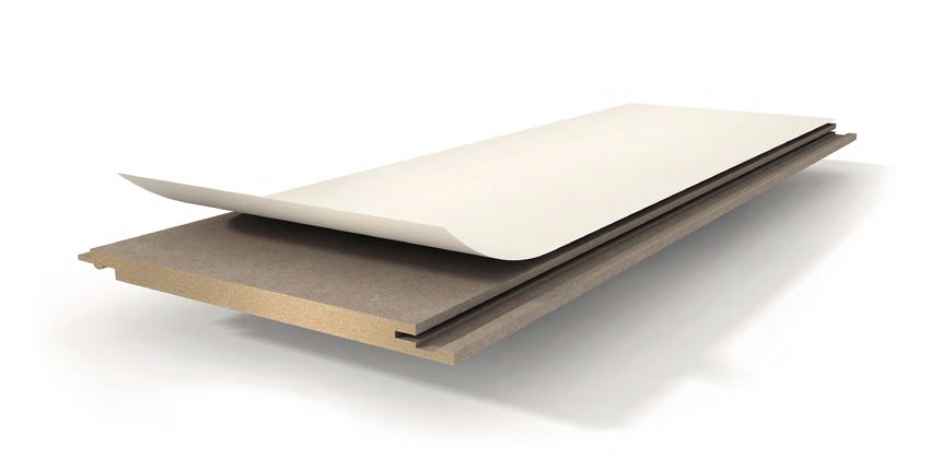
PANELS II TECHNOLOGY

Technology
Panels – structure
Novara / Home −Tongue and groove snap-on
panels

     1

 2

                                                    3

1                                                                        2
Decor paper                                                              MDF core board
The elaborately reproduced decors are fascinating with amazingly         The core, consisting of a medium density fibreboard, has a
genuine imitations of many natural materials. The decor print            particularly high breaking and bending strength. The core board
impresses with extraordinary brilliance using solvent-free paints.       complies with the E1 international emission values.
Impregnation with melamine resin additionally protects against
moisture and mechanical stress.

3
Tongue-and-groove snap-on connection
Thanks to the tried-and-tested tongue and groove snap-on connection,
ceiling panels can be quickly and easily attached to substructures.

          Suitable for damp rooms                          Tongue-and-groove snap-on               Light installation suitability
                                                           connection

          Lightfast

 Panels design                        Length [mm]           Width [mm]            Thickness [mm]     Board material        Fixing in the surface
                                      Calculated dimensions Calculated dimensions

 Novara                               1250 / 2050 /           200               10                   MDF                   Profile claw 3 for tongue
                                      2570 / 3300 / 4100                                                                   and groove panels
 Home                                 1250 / 2570             149               10                   MDF                   Profile claw 3 for tongue
                                                                                                                           and groove panels

Benefits of the tongue and groove snap-on panel

› Classic look due to all-round 0-cm joint
› Traditional assembly
› Application areas: wall, ceiling and loft extension
› Ideal for renovating existing panel ceilings
› Ready-to-install
› PEFC
› 15-year guarantee                                                                                                                                3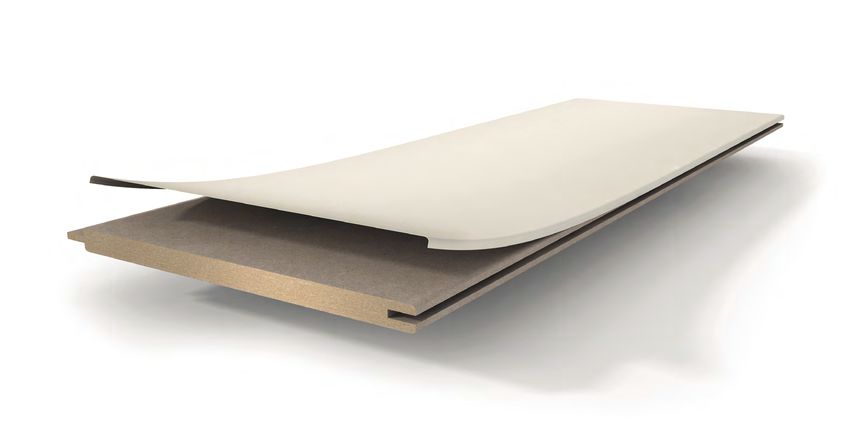
PANELS II TECHNOLOGY

Panels – structure
RapidoClick / MilanoClick / Style − Click panels

     1

 2

                                                    3

1                                                                            2
Decor paper                                                              HDF core board
The elaborately reproduced decors are fascinating with amazingly         The highly compacted, swell-protected core board offers high
genuine imitations of many natural materials. The decor print            dimensional stability and thus minimizes influences from climatic
impresses with extraordinary brilliance using solvent-free paints.       fluctuations or unusual loads. The all-round edge impregnation also
Impregnation with melamine resin additionally protects against           provides excellent edge swell protection.
moisture and mechanical stress.

3
Click mechanism
The patented click mechanism makes installation easy and the
connection is secure.

         Suitable for damp rooms                           Click mechanism                         Light installation suitability

         Lightfast

 Panels design                        Length [mm]           Width [mm]            Thickness [mm]     Board material        Fixing in the surface
                                      Calculated dimensions Calculated dimensions

 MilanoClick                          2585                    289                12                  HDF                   Fastening claw
                                                                                                                           for click panels
 RapidoClick                          1280 / 2050 / 2585      223                12                  HDF                   Fastening claw
                                      3300 / 4100                                                                          for click panels
 Style                                1280 / 2585             182                10                  HDF                   Fastening claw
                                                                                                                           for click panels

Benefits of the click panel

› Modern look due to delicate design joint
› Convenient assembly due to click mechanism
› Application areas: wall, ceiling and loft extension
› Ideal for renovating existing panel ceilings
› Ready-to-install
› PEFC
› 15-year guarantee                                                                                                                            4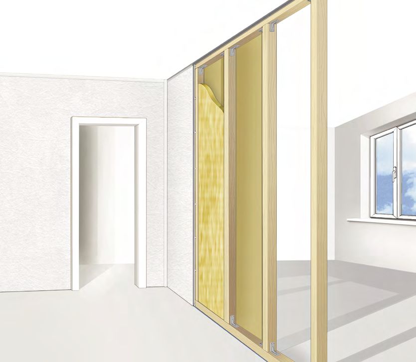
PANELS II TECHNOLOGY

Panels – application
Tongue and groove snap-on panels

Substructure                             Fasten first snap-on panel   Put fastening claw in place                Screw on fastening claw

Push in snap-on panels                   Fit moulding clip            Push on ceiling end mouldings – finished

Click panels

Substructure                             Fasten first snap-on panel   Put fastening claw in place                Screw on fastening claw

Pivot click panels into place            Fit moulding clip            Push on ceiling end mouldings – finished

                                                                                                                                           5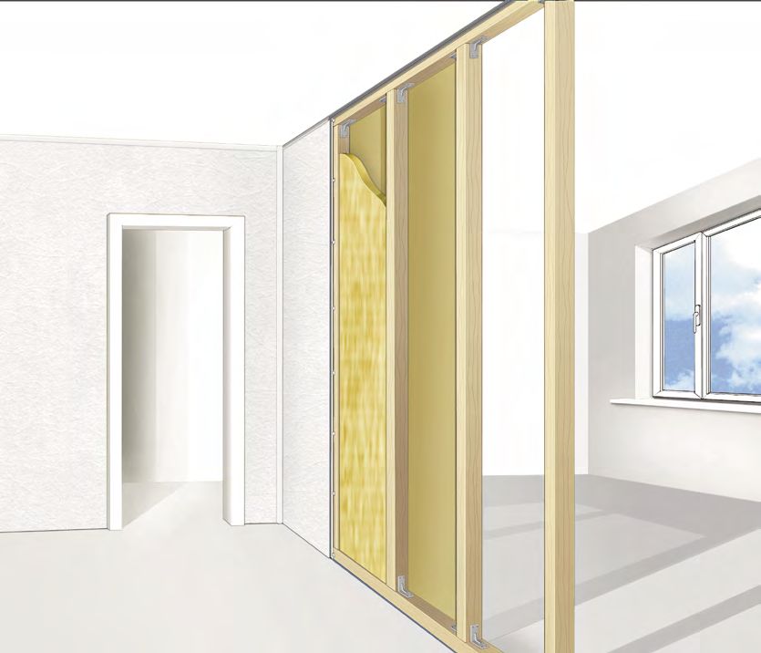
PANELS II TECHNOLOGY

Panels – System materials

The description of the technical versions of the panels can be found in the previous section
»Panels structure«.

Fastening claw

Panel claws are available in two different versions for fastening Parador panels. The tongue and
groove principle on the Novara and Home panels requires claws for a groove side thickness of
3 mm (profile claw 3 for tongue and groove panels), while the click principle on the other click
panels with a groove side thickness of 4 mm requires the fastening claw for click panels. The
claws are suitable for fastening using screws as well as with staples. We recommend using
staples with a length of at least 14 mm and a width of 10 mm.
Both panel claw systems are available in packs of 125.
Quantity planning is based on the spacing of the substructure and the respective cover width of
the panel.                                                                                                                 Fastening claw for click panels

For Novara, the maximum panel area to be fastened with a pack of panel claws is 8 m²
(room width 4 m) with a maximum gap in the substructure of 400 mm.

For Home, the maximum panel area to be fastened with a pack of panel claws is 7 m²
(room width 4 m) with a maximum gap in the substructure of 400 mm.

For MilanoClick, the maximum panel area to be fastened with a pack of panel claws is 17 m²
(room width 4.2 m) with a maximum gap in the substructure of 600 mm.

For RapidoClick, the maximum panel area to be fastened with a pack of panel claws is 13 m²
(room width 4.2 m) with a maximum gap in the substructure of 600 mm.

For Style, the maximum panel area to be fastened with a pack of panel claws is 8 m²
(room width 4 m) with a maximum gap in the substructure of 400 mm.

DAL 1                                               DAL 2                                                    DAL 3

Ceiling end mouldings

After the complete surface installation, attach the matching ceiling
end mouldings using the patented clip technology. There is a choice
of different moulding shapes, all of which are invisibly fastened with a
moulding clip.
In case of renovation, the ceiling end mouldings are easy to dismantle
(e.g. for wallpapering or painting work). If possible, join the mouldings
at inconspicuous places and cut them into mitre joints in room corners.

Decorative external and internal corners in white and aluminium look
                                                                            External and internal corners for ceiling end mouldings DAL1 and DAL2 in aluminium look
are available for mitre transitions.

In addition to the ceiling end mouldings (DAL 1, 2 and 3), special mould-
ings are available for particular applications.
                                                                                                                                                                      6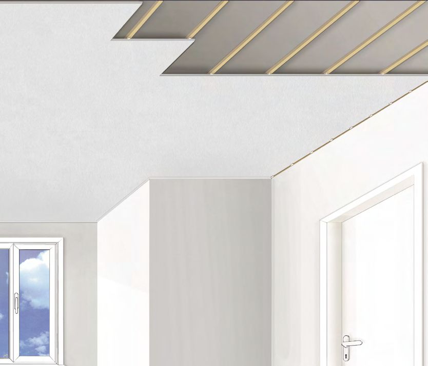
PANELS II TECHNOLOGY

A classic concave moulding (HKL) for fixing without clips by gluing or
pinning.

                                                                             HKL                                   FL 1
A rebate moulding (FL 1) to cover the view into the substructure area,
which is visible when walls and ceilings are not completely clad.

The rebate moulding (FAL) can be folded and is used to cover internal
and external corners and transitions (e.g. dormers and sloping roofs).
It can be glued or inserted into the groove geometry of tongue and
groove snap-on panels. Due to the hygroscopic properties of the
materials used, we recommend gluing the rebate moulding on one
side only.                                                                   FAL                                    FAL
                                                                             Folded outwards to                     Foldable moulding for neat
                                                                             cover the transitions from             transitions for non-rectangular
                                                                             dormers to the sloping roof.           connections from 1° to 180° and
                                                                                                                    for covering the transition from
                                                                                                                    sloping roof panelling to the
                                                                                                                    ceiling.

Clip for ceiling end mouldings

In order to fasten the ceiling end mouldings with the clips, short fasten-
ing profiles are inserted into the groove of the end mouldings at the
end of each moulding and at a distance of about 50 cm between them.

Now fasten one moulding clip each in the areas of a fastening profile           Guideline                                     Clamping slot
using the enclosed screw. To align the moulding clips for even walls,                                                         for guideline
use the wall as a stop line; for uneven walls, use a guideline.                 Stop line to
                                                                                wall                                          Long screw slot
                                                                                                            Contact edge

Adhesive points supplied make fastening easier.

Then simply push on the end mouldings.

                                                                                                                                                       7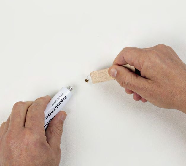
CLICKBOARD II TECHNOLOGY
ClickBoard – structure
1
2
3
4
6
5
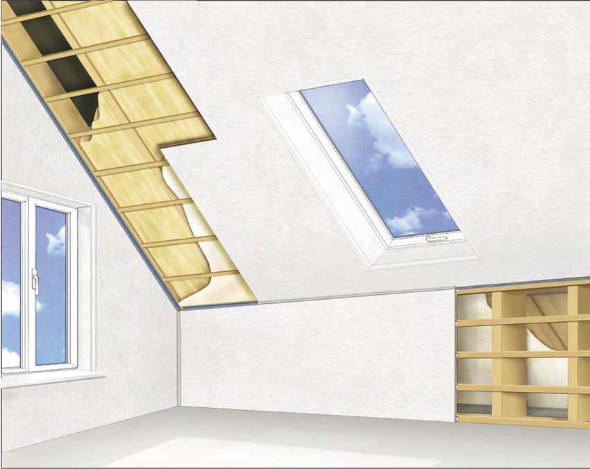
1 2 3
Overlay Decor paper Barrier paper
The highly abrasion-resistant and waterproof The elaborately reproduced decors are fascinat- Conceals the colouring of the carrier material
top layer made of melamine resin with ing with amazingly genuine imitations of many for a thoroughly clear decor look.
embossed texture provides an authentic feel natural materials. The decor print impresses with
and effective protection. extraordinary brilliance using solvent-free paints.
Impregnation with melamine resin additionally
protects against moisture and mechanical stress.
4 5 6
HDF core board Backing Safe-Lock ®
The highly compacted, swell-protected core The back of the ClickBoard is formed by the Thanks to the patented click mechanism
board offers high dimensional stability and backing paper, which compensates for tension with Safe-Lock ® profile, the planks snap into
thus minimizes influences from climatic fluc- and prevents the ClickBoard from warping. At the place easily and can thus be assembled
tuations or unusual loads. The all-round edge same time it protects the core board against quickly and easily.
impregnation also provides excellent edge moisture penetrating from the wall or ceiling.
swell protection.
Suitable for damp Light installation Lightfast Safe-Lock ®
rooms suitability
Design Length [mm] Width [mm] Thickness [mm] Board material Fixing in the surface
Calculated dimensions Calculated dimensions
ClickBoard 1285 389 12 HDF ClickBoard
centre clamp
2585 389 12 HDF ClickBoard
centre clamp
2585 492 12 HDF ClickBoard
centre clamp
Benefits of ClickBoard
› Almost invisible joint
› Quick installation thanks to wide ClickBoards and convenient click mechanism with Safe-Lock ® profile
› Easy to maintain, durable and highly resilient
› Application areas: wall, ceiling, roof extension and lightweight partition wall
› 15-year guarantee
› PEFC 8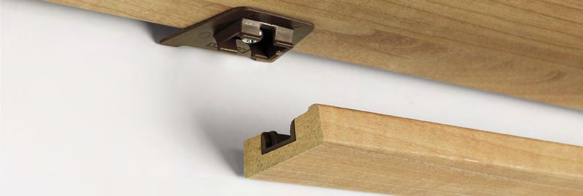
CLICKBOARD II TECHNOLOGY

ClickBoard – Application
Anyone who wants to extend their roof, install or renovate walls or ceilings, has a lot to do and little time.
ClickBoard is fully assembled in just a few work steps and immediately ready-to-install without the need for
filling, sanding, painting or wallpapering, so that the interior can be completed more quickly.

Substructure                          Put fastening rail in place            Insert first panel                  Put centre clamp in place

Click                                 Fastening rail for last panel          Push on HDF mouldings               Finished

                                                                                                                                             9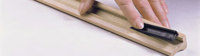
CLICKBOARD II TECHNOLOGY

ClickBoard – system materials

The description of the technical versions can be found in the previous
section »ClickBoard structure«.

ClickBoard HDF moulding system for fastening the borders
and covering the border spacings

To fasten ClickBoard in the first and last row and to cover connections
and transitions in different room situations accordingly, you can choose
between two different moulding designs (end and universal moulding).
These mouldings (HDF mouldings coated with high-quality decor paper)
are fastened by the rail retaining moulding system. They are made of
high-quality plastic. The fastening rail, the retaining moulding and the
necessary fastening screws for wooden substructures are included.

                                                                              Universal moulding

Centre clamp

The ClickBoard centre clamp is used to attach ClickBoard to the sub-
structure. It is used on the long side of ClickBoard. There it is placed
on the protruding groove side and fastened to the substructure with
the aid of a screw. This provides an invisible and floating fastening
of ClickBoard. Centre clamps for wooden or metal substructures are
available. The necessary fixing screws for a wooden substructure are
included.

                                                                              Centre clamp

Spacer

To ensure the required border spacing, the spacer is inserted into the
fastening rail. Due to the existing geometry it already fixes itself in
place using light pressure. After installing the ClickBoard surface, it can
simply be pulled out of the fastening rail.

                                                                              Spacer

                                                                                                   10
CLICKBOARD II TECHNOLOGY
Corner joint for HDF moulding
When installing end mouldings in 90° corners, the corner joint can
optionally be used for a secure mitre connection.
Corner joint for HDF moulding
Connector 90°
Two fastening rails can be pre-installed with the 90° connector to
simplify installation on 90° external corners and thus facilitate the
fastening process. The 90° connectors used must be dismantled
after the fastening rails have been fitted.
Connector 90°
Hammering block and drawbar
The use of a hammering block is required to join the short edges
together. It must fit tightly and must not tilt when being hit with the
hammer. The drawbar is used to put the short edge together on the last
plank of an installed row. The hammering block is not suitable for this
purpose.
Drawbar
Hammering block
11CLICKBOARD II TECHNOLOGY
Borders with ClickBoard HDF moulding system
Connection corner
For surfaces running at right angles to each
other, e.g. interior room corners or ceiling
ends.
(End moulding)
External corner
For surfaces running at right angles to each
other and forming an external corner, e.g. wall
openings or window reveals.
(2 universal mouldings and connector 90°)
Internal corner flexible
For all surfaces running diagonally to each
other and forming an internal corner,
e.g. sloping roof transition or jamb wall.
(Universal moulding and spacer)
12CLICKBOARD II TECHNOLOGY
External corner flexible
For all surfaces running diagonally to each
other and forming an external corner, e.g.
dormers.
(2 Universal mouldings)
Transition
Perfectly conceal expansion joints. They can
also be used as a substitute for connection
profiles or flexible inner corner profiles.
(2 end mouldings)
Internal corner with two HDF mouldings
(2 end mouldings)
Internal corner with one HDF moulding
(Universal moulding)
13GENER AL II INSTALLATION
Installation
In addition to the installation rules specified here, the special installation
instructions specified in the following chapter "Areas of application"
must be observed.
General
Inspection for material defects
The panels should be checked thoroughly for material defects before
and during installation. Panels with visible defects or damage must not
be installed. Assembly should only take place under daylight or with
adequate lighting, as otherwise any damage or faulty panels cannot be
detected in some circumstances.
Acclimatisation before installation
The panels must be acclimatised over a period of at least 48 hours at a
room temperature of at least 17°C and a relative humidity of 35 to 60%
in the room where they are being installed. That means that the sealed
packages must adjust to the climate conditions in the room. If there are
major climate differences between the storage area and the room of
installation, the acclimatisation period should be longer preferably. If the
climate conditions are almost the same, the period can also be shorter.
Please store the packages on an even base without opening them. It
is essential that you comply with these points, especially in new builds
where the humidity is usually very high.
Inspection of the building structures
The building structure to be clad must not be defective. This means
that it must be tightly sealed by plastering or filling. Furthermore, the
existing building fabric must not show any moisture influences or
mould damage.
Panels and ClickBoard can be installed on wooden and metal substruc-
tures, which must be professionally executed according to the manu-
facturer's specifications. In order to achieve a perfect end result, the
substructure must be precisely aligned and guarantee a level installation
surface (tolerance: micrometre 1 mm over 1 m length).
14APPLICATION II INSTALLATION
Application
Substructure
For a simple panel installation, a well aligned substructure at right angles
to the long edge of the panels is required (exception: ClickBoard wall).
Direct wooden substructures usually consist of one or two wooden
battens (counter battens). In the case of double battens, an additional
base batten is installed in the opposite direction between the supporting
batten and the ceiling. The installation is carried out with suitable screws
and dowels at a distance of 40 to 50 cm apart. The user achieves height
compensation by placing spacers underneath.
The direct fastening of a metal substructure is carried out using
commercially available profiles. The height adjustment is carried out with
adjustable profile fastenings or also by placing spacers underneath.
Outlining and averaging out
Once the substructure has been installed, the surface to be laid should
be centred in all directions. This gives the surface an optically uniform
impression later on. For averaging out, the width and length are divided
by the format width or length. The value that remains beyond the full
formats is divided on both sides. Please make sure that the end joints of
the panels are even so that the groove at the end of one row is aligned
with another groove at the end of another row. An end joint does not
necessarily have to lie on a substructure batten.
ClickBoard is installed in the so-called random bond. This means that the
remaining piece from the last area is the first piece of the next row.
Distances to be observed
The centre distance of the substructure for ceilings and roof extensions
corresponds to 40 cm max. (Novara and ClickBoard) or 60 cm
(RapidoClick, MilanoClick). When fitting vertically installed ClickBoard,
the substructure must be positioned under the panel joint.
Border spacing to adjoining components/walls/ceilings
Due to the wood-based material of the panels and ClickBoard, a border
spacing must be maintained (shrinkage and swelling due to climate
fluctuations). This distance is achieved with panels by aligning and fixing
the individual panels (all round 7 - 10 mm).
With ClickBoard, this distance is ensured by the border wedges or
spacers. If ClickBoard measurements have to be recorded, the measure-
ments have to be taken up to the spacers, which have to be used on all
sides for this purpose. For wall and jamb installation, ClickBoard can be
placed directly on the floor and only needs the border spacing above and
to the side. Please prevent direct water contact at the ClickBoard cutting
edge. When fitting the first and last panel, we recommend pre-drilling
and screwing with a larger diameter to allow the panel to expand.
15APPLICATION II INSTALLATION
Distance of the click connection to the border or to openings
When outlining the installation pattern, care should be taken to keep
a gap of at least 10 cm in case of border spacings and gaps in the area
(e.g. window openings and doors) to the respective click connection.
In some cases it may therefore be necessary to move the installation
pattern, centre it accordingly and start with a suitably short panel.
Distance to penetrations in the surface
As soon as the surface is penetrated by e.g. rafters, radiator pipes
or fastenings in structures below the planking, the specified border
spacing also needs to be maintained all the way round.
Offset joints
If panels or ClickBoard are laid interlocked, the lateral joints should be
offset by a minimum of 40 cm. This improves the stability of the surface
and its optical impression.
Maximum installation length/width
Only areas up to a maximum length of 8 m (lengthways or crossways)
can be installed continuously with panels and ClickBoard. On larger
installations, expansion joints need to be incorporated, which can be
easily covered up by a matching transition profile when using panels.
With ClickBoard, two end mouldings are used for this purpose.
Cutting waste
On a continuous installation, around 1-5 % waste should be reckoned on
depending on the method of installation, cutting optimisation etc. In the
case of more sophisticated installation patterns, this value may also be
exceeded.
16ASSEMBLY SEQUENCE II INSTALLATION
Assembly sequence
Panels
For assembly in the first row of panels (starting on the left), the tongue
section must be cut off. On the wall side, the panels (border spacing)
are screwed or pinned directly onto the substructure and fixed in place
with the corresponding centre clamps. 2
On panels, the short edge joints are made by sliding in (with tongue
and groove snap-on panels) or by pushing the groove section up close
(a ship lap is produced with click panels) onto / up to the tongue of the
panels already installed. No special tools are necessary for this.
Assembly can be done by hand. A strip-shaped development of three
rows of planks at the same time can make the assembly process
easier.
Tongue and groove panels are pushed horizontally in both directions,
whereas click panels are pivoted into place (starting angle 10 – 20°).
For installing the last row, the distance of the visible installation area to
the wall is measured and the panel being fitted is cut to size (bear in
mind border spacing). After that the panel is pushed/pivoted into place
as usual and, as with the first row, fixed in place by screwing/pinning
directly onto the substructure.
17ASSEMBLY SEQUENCE IIINSTALLATION
ClickBoard
The fastening rails are screwed on all around the ClickBoard area being
installed. Next, the corresponding retaining profiles and spacers are put
in place on the long side of the starting row. In this section the panels
on the first row (starting on the left) are now pushed in up to the
spacer. For this purpose the click profile (tongue side) must be cut off.
After pushing into place and screwing the centre clamps, the Click-
Board is fixed in place.The short edges can be joined together with the
aid of the hammering block. So that the ClickBoard can be knocked
flush into each other, a remaining portion on the transition of the two
areas should be clicked in on the open side of the installation row.
Before inserting the last ClickBoard in the first row, the required length
must be calculated and the ClickBoard cut to length – with a difference
of 12 mm, as the short edge has to be joined together using the draw-
bar. The other rows of the area being panelled can now be installed.
Pivot ClickBoard into place (starting angle 10 – 20°), join end edge, cut
last ClickBoard to length and fit it (remaining piece can be used to start
the next row). (Take care to rest it on at least 2 substructure battens).
For the last row you need to measure the distance of the visible
installation area to the spacer installed. The ClickBoard being fitted is
cut down to this size. After that it is pivoted into place as usual and
ultimately fixed in place by screwing the retaining profile together with
the fastening rail.
18MISCELL ANEOUS II INSTALLATION
Fitting the ceiling end mouldings
The end mouldings can be easily cut to size in a mitre box with a
precision saw. After installing the whole area, the ceiling mouldings
are fastened with the aid of moulding clips in the case of panels.
With ClickBoard the corresponding end mouldings are cut down to size
and pushed onto the retaining profile.
Please think about using the corner connector here when
fitting the end mouldings at 90° to the mitre joint
Miscellaneous
Panel assembly on smaller areas
For smaller surfaces of ≤ 2.60 m × 0.50 m, e.g. window reveals, the
surface can be glued using Parador construction adhesive or also
screwed underneath the profiles. In this case the movements of the
wood material are so small that the clip clearance can be ignored.
Finishing with system accessories – otherwise no guarantee
Parador products should be finished using all the Parador system
accessories. If other materials, such as standard screws or similar are
used, no guarantee is provided by the manufacturer.
Planning the wiring of electrical installations
Before the substructure is installed, the planning of electrical installa-
tions should be completed. Bear in mind the necessary gap between
the substructure profiles and planned recessed spotlights, or the
presence of a sufficiently sturdy substructure close to where heavy
lights are suspended.
19CEILING II APPLICATION AREAS
Application areas
Ceiling
Crucial benefits of cladding a ceiling are the optical enhancement of
defective existing bare ceilings, the variation and application options
of light systems, the fitting of installation cables, the improved sound
insulation to apartments above, but also the ability to reduce the height
of ceilings with a suspended installation. By reducing the volume of
the room, a suspended ceiling provides heating cost savings and an
improvement in heat and airborne sound insulation. When cladding
ceilings, there is a choice between a direct substructure made of wood
or metal. Alternatively there is the option of reducing the ceiling height
with special suspension systems. For suspending a ceiling on greater
heights, conventional suspension systems made of metal can be used.
If you do not use the Parador system materials or suggestions, please
make sure that the materials chosen by you are adequately safe for the
application. Please think about adequately securing components that
may fall down. There are assembly aids and ceiling supports for this
purpose.
Recommended format for panels:
any
Recommended format for ClickBoard:
1285 mm × 389 mm
20WALL II APPLICATION AREAS
Wall
There are many good reasons for enhancing existing walls with cladding
using Parador panels. Besides the variety of designs, you are able to
insulate walls in terms of heat and noise protection, cover up installa-
tions, or to make bare walls more attractive in a simple way. The prepa-
ration work is limited to installing the substructure in accordance with
the general assembly method and corresponding additional functions
such as heat insulation. When using insulating materials, you may need
to bear in mind the need for a vapour barrier between the insulation and
substructure. Panels can be attached both horizontally and vertically.
ClickBoard should only be attached vertically. On doors and window
openings, the fastening rails are also screwed onto the substructure
all the way round. They are later used to fasten ClickBoard at the sides
and prevent the area from sliding down. The fastening rails are not
necessary where the panels meet the floor, as they can be placed
directly onto it. On doors and window openings, fastening rails are also
screwed onto the substructure all the way round. They are later used to
fasten ClickBoard at the sides and prevent the area from sliding down.
Recommended format for panels:
any
Recommended format for ClickBoard:
any
Installation options
Application: horizontal panels Application: vertical panels Application: ClickBoard
21LOF T E X TENSION II APPLICATION AREAS
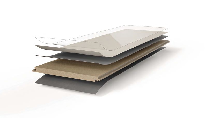
Loft extension
The benefits of a loft extension with Parador panels include preparing
additional living space in a short time, utilising existing room resources
and gaining living space cost effectively. Since a loft extension basically
involves a change of building utilisation, a building permit is required
(depending on the federal state). The wood substructure is most
frequently used in loft extensions. It should be noted here that a vapour
barrier needs to be incorporated between the rafters and substructure.
It is still possible to use metal profiles. Either top hat ceiling profiles or
CD profiles can be used with appropriate fastening clips. In this case
any difference in height is compensated using height adjustable screws
or also distance wedges.
Recommended format for panels:
any
Recommended format for ClickBoard:
2585 mm × 389 mm
1258 mm × 389 mm
Special assembly features
If panelling is being done on more than one side, the following
sequence needs to be observed: walls; jamb walls, pitched ceiling,
ceiling. Each step, from making the substructure to panelling, should be
fully completed before starting the next application area. The individual
loft areas are to be treated as if they were wall or ceiling areas. Only in
adjoining areas from the slope to the ceiling or from the slope to the
wall, does a loft extension differ from the assembly methods described
above. Please bear in mind when installing panels horizontally that on
panels with a click system, depending on the pitched ceiling, in addition
to the click connection the panels must be held with a vice-grip wrench
or similar until they are finally screwed in place.
Loft extension with ClickBoard
In the pitched ceiling area, the jamb wall is first clad with ClickBoard.
First of all the fastening rails are attached to the wall (ClickBoard wall)
on the right and left. The length of the ClickBoard for the jamb wall is
the distance between the floor and the pitched ceiling minus 6 mm.
After the jamb wall, the slope is fitted. Firstly the fastening rails are
screwed onto the substructure on the right and left. Then the horizontal
fastening rail between jamb wall and slope is screwed on. To ensure
that the HDF moulding fits accurately, we recommend using an
assembly aid. Once the fastening rail between jamb wall and slope is
fitted, the area is panelled. When doing this, the ClickBoard can be set
down onto the fastening rail. The length of the ClickBoard results once
again from the distance between the fastening rail and ceiling substruc-
ture minus 6 mm. After that the ceiling is fitted. The universal profile is
used for fastening the edges on the transition from ceiling to slope.
22LIGHT WEIGHT PARTITION WALL II APPLICATION AREAS
Lightweight partition wall
(Only ClickBoard)
The benefits of a lightweight wall are the safe and simple creation of
a partition wall without a lot of dirt and rubble, the efficient housing
of installations and the short assembly and dismantling time without
drying and waiting times. The ready-made assembly system achieves
high flexibility and a cost advantage over conventional solid walls.
Furthermore, the easy to handle formats ensure easy transport and safe
handling. Lightweight walls can be used as a partition inside an apart-
ment, but not as a wall between apartments. When fitting lightweight
partition walls in interior construction, a wooden framework is normally
used. The wood frames should be dry and straight before installation.
As a material, wood is easy to work with, but can involve stresses due
to its property of “shifting”. As an alternative to this, a metal framework
with counter-battening made of wood can also be selected. The reasons
for this are: better sound insulation, warp and torsion-free, simple
assembly and strict tolerances. The sound insulation to adjoining rooms
is increased by inserting an insulating material in the cavity under
the substructure. A well aligned substructure also makes it easier to
assemble ClickBoard and provides the basis for perfect final results in
dry construction. To achieve this aim, it is very important to level the
substructure.
Recommended format:
2585 mm × 492 mm
2585 mm × 389 mm
Centre distance of centre clamps:
max. 40.0 cm
Centre distance of substructure:
492 mm or 389 mm
Assembly sequence
Outlining the installation pattern
To outline the installation pattern, the course of the future wall is drawn
on the floor using a string line, a plumb line, a spirit level or a laser. The
outline is then transferred with the aid of a spirit level or a laser across
the adjacent wall up to the ceiling. Once the outline has been marked,
the position of the supports needs to be determined. For the panelling
there must be a support underneath every click connection (distance to
centre clamp 40 cm max.). To do this, the area is centred laterally by
dividing the width of the wall by the format width used and the remain-
ing value divided evenly on both sides.
23LIGHT WEIGHT PARTITION WALL II APPLICATION AREAS
Substructure and cavity insulation
The top and bottom square timbers/UW profiles are fastened and aligned
first on the markings already made followed by the side square timbers/
CW profiles. In particular the side square timbers/CW profiles are
fixed to the wall with plugs at an interval of 1000 mm or at least three
fastening points. For sound insulation reasons and for sealing purposes,
conventional insulating strips are placed under the supports/profiles all
the way round. Care should also be taken that the lateral CW profiles are
fastened by force fit to the existing walls. In this way, any deformation
of the profiles is ruled out when panelling. At an interval of the selected
format (2585 mm x 492 mm; 2585 mm x 389 mm), the metal supports
are then pushed in according to the centering process, but not screwed.
Please also fix the profiles in the top and bottom area to the UW profiles
using a punch lock riveter. The metal supports have to stick into the top
profile at least 1.5 cm after alignment. The wood supports are fastened
to each other with brackets. Align the wall precisely with the help of the
laser (which your dealer will lend to you). The inside cavity insulation and
wiring can be inserted after assembling the first panelling side. Please
bear in mind the manufacturer's assembly instructions when making the
framework.
Fastening the fastening rail
The fastening rails should be screwed onto the substructure flush to
adjacent walls and ceilings. On doors and window openings, fastening
rails are also screwed onto the substructure all the way round.
Installation height > 2.58 m
If a room is over 2.58 m high, the panels are installed interlocked. If
installation is done with a head joint, the last panel on the installation row
is interlocked using the drawbar. Particular attention should be paid at
this point to the border spacing of 12 mm. Furthermore, the lateral joints
should be offset by at least 40 cm.
24DIY TIPS II MORE
More
Tips
Assembly options with "non-pivotable panel"
As it is no longer possible to pivot panels in place where holes have been made in the surface
(e.g. radiator pipes, rafters or fittings on recessed support structures etc.), ClickBoard needs to
be hammered down and glued in these cases. For this purpose, the round part of the profile on
the click connection must be removed on the long side with a knife. Once glue has been intro-
duced to the groove, the panel can be inserted with a hammering block.
Moisture protection
To prevent damp penetrating the insulation from condensation, a vapour barrier needs to be intro-
duced between the substructure and insulation material. For this purpose, mathematical proof is
to be provided by an expert planner.
Renovating panelled ceilings
It is also possible to renovate existing panelled ceilings with panels and ClickBoard. In this case
the existing panelled area is removed and the old substructure used as base battening. Please
check that the old substructure is secure! Similar to installing double timber battening, the
support battens are fitted all the way round and at right angles to the existing substructure at a
centre distance of 40 cm.
Gluing ClickBoard behind radiators
Due to high temperatures and thus very dry air, the click connections behind and in the vicinity of
approx. 1.5 m from radiators should be additionally glued with the help of Parador D3 joint glue.
This prevents splits in the surface and also guarantees a sound optical impression even if the
temperature or humidity is not maintained for a short period.
Assembly aid
In situations where the fastening rail does not rest on a wall or a corner solution is produced
using the 90° connectors, you should put together a small assembly aid.
Create an Position Fasten Assemble Push HDF moulding
assembly aid fastening rail fastening rail retaining profile on
25FASTENING LOADS II MORE
Have you thought of everything?
To make sure that you are not missing anything when you start your renovation work, we have
put together a small list for you, which normally includes everything you need:
› Straight edge to check the surface is level
› Enough profiles (at least 19 × 40 mm) and fastening materials for the substructure
› Enough panel claws/clips incl. fastening material and end mouldings (if nec. with retaining clips)
with fastening material
› Take panelled areas with cutting waste into account and store them in the installation room for
48 hours before assembly
› Are you using a metal substructure? For the ClickBoard HDF moulding system, the screws
supplied for the fastening rails (interface between rail and substructure) must be replaced by
suitable self-tapping screws (min. M4x20).
› Jigsaw or hand-held circular saw: when machining, the panels or ClickBoard should be
machined with the reverse side facing up. This will prevent fraying on the visible edge
resulting in a neat cut. Furthermore, contamination and damage to the finished surface is
prevented by the skids.
› Other tools: ladder, cordless screwdriver, tape measure, spirit level and if nec. a craft knife, a
drill to make exact drill holes in recesses for cavity wall sockets or recessed lights, for example.
Suitable drill attachments are available in trade shops.
Fastening loads
Fastening loads is no problem at all with ClickBoard. A key benefit of wood as a material is its
relatively high load bearing capacity compared to other dry construction systems.
Fastening elements
Building elements (loads) are normally fastened to the ClickBoard with wood or chipboard
screws. Using special plugs is not necessary when fastening to the panel. The max. thread depth
is 15 mm. As a matter of principle, care should be taken that the screw does not penetrate the
substructure, thus fixing the ClickBoard wall in place.
When using screws ≤ 3.5 mm diameter, before screwing them in a flat drill should be used to
make a hole in the surface. With screws >3.5 mm diameter, the panels should be pre-drilled.
You must not drill too much, otherwise the self-tapping thread made by screwing in cannot
achieve the required retention force. Generally you should pre-drill somewhat smaller than the
core diameter of the screw being used.
26FASTENING LOADS II MORE
Ceiling installation area
ClickBoard
Light to medium individual loads up to 10 kg (lights etc.) can be fastened directly to the
ClickBoard using wood or chipboard screws. Care should be taken that the screw does not Substructure
penetrate the substructure. If attaching heavy loads, the supporting substructure should be
used to hold the weight. The required gaps of 10 mm to the parts penetrating the ClickBoard
should be ensured.
max. 10 kg
Wall installation area
Permitted load per ceiling area unit
(40 cm × 77.8 cm (2 × 38.9 cm))
Light to medium individual loads (pictures, wall lights etc.) can be fastened directly to the
ClickBoard using wood or chipboard screws. Care should be taken that this screw does not
penetrate the substructure.
Fastening shelves / cupboards
The following values relate to wood or chipboard screws with a minimum external diameter of
3.5 mm and to wall heights up to 3 m.
Number of fastening points
Maximum load per screw Fastening shelves/cupboards
Shelf/cupboard depth a [cm] 25 30 40 50 60
Permitted load
per m of wall length [kg] 126 121.5 117 108 100
Shelf/cupboard width b [cm] 45 60 80 100 45 60 80 100 45 60 80 100 45 60 80 100 45 60 80 100
Max. shelf/cupboard weight [kg] 56.5 75.5 101 126 55 73 97.2 121.5 52.5 70 93.5 117 48.5 64.8 86.5 108 45 60 80 100
Number of fastening points [min.] 2 2 3 3 2 2 2 3 2 2 2 3 1 2 2 3 1 2 2 2
Selection table for fastening shelves/cupboards to the ClickBoard wall
27FASTENING LOADS II MORE
› The loads introduced should be evenly distributed on the shelf or in the cupboard where possible.
› When attaching loads with the fastening going into the supporting substructure, the
required gaps of 10 mm to the parts penetrating the ClickBoard should be ensured.
› When fastening objects to the ClickBoard wall that exceed the specified values, stability
reinforcers (support stand crossbars or similar) need to be made in the substructure in
accordance with the manufacturer’s specifications.
› If the situation is unclear, the advice of specialists (structural engineer, expert tradesperson etc.)
should generally be sought.
28SURFACE FINISHING II MORE
Surface finishing
Painting
Finishing panels by subsequently painting them can be done immediately or even after years.
Depending on the paint material used, it may be necessary to apply a primer. When finishing
panels by painting them, as with creative techniques, the application instructions of the respec-
tive manufacturer should be observed. If adjoining walls are intended to be matched to the
ClickBoard colour shades, your specialist paint dealer can create the required colour using special
mixing techniques. Please only use high quality paints (emulsion or latex paints). Furthermore,
please check that the paint adheres properly by doing a test. If areas need to be taped off when
painting panels, please use a suitable paintwork adhesive tape.
Wallpapering
It is possible to subsequently finish ClickBoard by wallpapering at any time. After priming with
penetrating primer for example, the wallpaper can be applied. All standard wallpapers can be
used for this purpose. Only vinyl wallpapers are unsuitable for ClickBoard. When wallpapering,
please observe the manufacturer’s application instructions, which among other things also
include how to use the product-related adhesive. If no instructions are available, wallpapering on
ClickBoard should be done with special pastes (e.g. Metylan- Spezial). Due to the joint situation,
subsequently wallpapering panels is possible, but only recommended under certain conditions.
ClickBoard texture primed
If the assembly benefit from the click mechanism is desired and you want to save doing un-
pleasant steps like filling and sanding, but the variety of the ClickBoard colour range does not
meet your expectations, the primed ClickBoard can be used as another alternative. Depending on
the paint or wallpaper used, it may be necessary to apply a primer e.g. penetrating primer. Fur-
thermore, as with creative techniques, the manufacturer’s application instructions for wallpapers
and paints should be observed.
29MAINTENANCE, REPAIR / TR ANSPORT, INSTALL ATION TIMING AND SITE CONDITIONS II MORE
Surface maintenance
and repair
The surfaces of panels and ClickBoard are extremely easy to maintain. The surfaces are wiped
with a damp, well wrung out cloth and a standard, non-film forming cleaning agent. Under no
circumstances must a steam cleaner be used.
Repair compound for ClickBoard
To further assist the durability of the ClickBoard product, special repair compounds have been
developed. Damaged areas on the ClickBoard surface (e.g. drill holes or scratches) can be
evened out using the ClickBoard repair compounds. These are available in different colours or as
a mixable set. Affected areas are lightly dampened with water and then filled with the ClickBoard
repair compound. In case of deeper damage in the surface, a further application should be made
after it has dried.
ClickBoard repair compound
Transport, installation timing
and site conditions
Transport
When transporting panels and ClickBoard, it should be noted that the packaging with edge
reinforcement does not act as a protection against strong impact (e.g. on staircases or room
corners). To prevent damage, the long formats (> 2 m) should be carried to the place of installa-
tion by two people
Installation timing and site conditions
› Cladding with panels and ClickBoard on new builds should be done after installing the windows
and once the screed has dried out.
› Working with panels and ClickBoard must be done at more than 17° Celsius and maximum
65 % humidity.
› As soon as the product is fitted in the loft extension of a new build, the roof timbers should be
dry for a few weeks (maximum wood moisture 18 %).
› Screeds may have the maximum following moisture content:
Cement screed max. 2.0 % CM
Anhydrite floating screed max. 0.5 % CM
Cement screed with underfloor heating 2.0 % CM
Anhydrite floating screed with underfloor heating 0.3 % CM.
› The existing building structure must be sealed, free of moisture effects and mould. For ques-
tions relating to the areas of building structure, structural engineering, fire protection, heat and
damp protection, the advice of an expert planner should be sought.
30GENER AL / CLICKBOARD AND PANELS II FREQUENTLY ASKED QUESTIONS
Frequently asked questions
General
1. In which rooms can Parador ClickBoard and panels be used?
Parador ClickBoard and decor panels can basically be used in all living rooms with a changeable
climate. Consideration must be given if installing into areas where water can come into contact
with Clickboard or panels , such as a bathroom or kitchen. Due to the constantly high humidity,
panels and ClickBoard are not suitable for use in swimming pool or spa areas.
2. When using Parador ClickBoard and decor panels in damp rooms, do I have
to observe special installation rules?
In principle, the duration of increased indoor humidity is significant. If a normal indoor climate
is restored after a short time, as is the case, for example, after showering with subsequent
ventilation, no special precautions need to be taken. As with all living space situations, it must be
ensured that there is no permanently acting humidity that enables mould to develop.
3. Can recessed lights be used in Parador ClickBoard and panels ?
Parador ClickBoard and panels are heat-resistant up to 110 °C and therefore suitable for the
installation and continuous use of recessed lights.
Panels
4. Is it really necessary to use end mouldings?
Due to the fact that the wood material expands and contracts with climate fluctuations,
a so-called expansion joint must be maintained on the finish to the wall or ceiling. The end
mouldings are the best solution for covering this necessary gap in an elegant manner.
5. Can panels be decorated?
If, due to renovation work, panels have to be painted, a suitable paintwork adhesive tape should
be used for taping off. If you intend to decorate, please also bear in mind that panels with a
mini-bevel must not be completely filled in the joint area.
6. Are panels lightfast?
Panels offer good light fastness in accordance with DIN ENISO 4892-2 against fading due to
sunlight.
31CLICKBOARD II FREQUENTLY ASKED QUESTIONS
ClickBoard
7. What are the building biological properties like, such as moisture control
and breathability, on ClickBoard?
ClickBoard is made of an HDF core board coated with melamine resin. This surface can easily
be cleaned and prevents a build-up of mildew or dust. For this reason the product is particularly
suitable for people with allergies. The moisture exchange on the wall surface is of minimal
significance. Many building materials like concrete, vinyl wallpapers, latex paints or tiles are not
moisture regulating either. What is critical for the indoor air quality is an appropriate exchange
of air from correct ventilation.
8. How does ClickBoard behave in terms of fire protection?
Parador ClickBoard is categorised in fire protection classification B2 according to DIN 4103-2
(Ds1d0 according to EN 13501). In order to achieve fire resistance classifications on walls or
in loft extensions, the structure must be tested as a whole. Parador ClickBoard should only
be seen as a decorative surface in this case and is not used for fire protection reasons. If fire
protection requirements need to be fulfilled, have the building structure checked by an expert
planner. Depending on the state building regulations, the requirements differ and are subject to
changes.
9. ClickBoard does not match the 62.5 cm construction grid pattern.
Does this result in problems, e.g. in the choice of insulating materials?
When it comes to loft extensions and the optional insulation of ceilings, common products can
be used as with conventional extensions. The gap between rafters, as well as the substructure
on ceilings, do not match the construction grid pattern in most cases, meaning that the insulat-
ing material has to be adapted. Widths of 1 m are supplied on mineral wool insulating panels.
These can be adapted to the centre distances of the ClickBoard substructure by being halved.
Usual insulating materials especially for partition walls (width 62.5 cm), on the other hand,
cannot normally be used, but must be installed crossways due to the difference in width. Care
must be taken that the width of the insulating material fills the cavity in the substructure to
prevent the material from “caving in”.
10. W
hat is the long-term behaviour of ClickBoard with regard to the joint
quality?
The joints on the product have been simulated and tested under extreme conditions by means
of climate tests. Under these above-average temperature and humidity fluctuations, no obvious
changes occurred at the joints.
32CLICKBOARD II FREQUENTLY ASKED QUESTIONS
11. Can ClickBoard be attached directly to a wood-based board or
plasterboard?
Because of the high amount of plugging work required, it is not recommended to fasten
ClickBoard directly onto plasterboard. If these walls are going to be decorated, however, it is
possible to attach an additional substructure with the prescribed centre distance. The easiest
method is to install wood battening crossways like a facing formwork, onto which ClickBoard
can be screwed directly. Panelling straight onto a wood-based board is no problem at all,
however. Please use the system screws for wood substructures for this purpose and check
the wood moisture of max. 18% on the panels being used.
12. How do I fasten Parador skirtings on ClickBoard?
The Parador skirtings cannot be fastened with the screws included in the packaging. These
are suitable for solid walls and must be replaced by shorter wood screws when fastening to
ClickBoard. (The screw length should be matched to the skirting and extension panel and
should not penetrate the substructure).
13. Is there any need for ClickBoard edge profiles?
The ClickBoard edge profiles are necessary due to the wood-based material. They form
an optically discreet cover for the border spacing required on ClickBoard and are therefore
indispensable. Unlike conventional dry construction, the profile solutions can absorb move-
ments e.g. when extending roof timbers, whereas with classic dry construction solutions,
cracks can form on wallpapers and paints. Alternatively, however, other solutions can be
carried out on site such as assembly with shadow joints.
33parador.de/en
Vinyl flooring | Modular ONE
Engineered wood flooring
Laminate flooring
ClickBoard | Panels
Mouldings and accessories
Parador GmbH
Millenkamp 7–8
48653 Coesfeld
Germany
Hotline +49 (0)2541 736 678
info@parador.de
www.parador.de
www.facebook.com/parador
Status: 05 / 2021 © Parador
Subject to errors and alterationsYou can also read