SERVICE MANUAL - Air-conditioner network controller Online Controller KKRP01A
←
→
Page content transcription
If your browser does not render page correctly, please read the page content below
Air-conditioner network controller

     Online Controller KKRP01A

          SERVICE MANUAL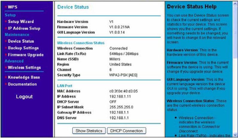
CONTENTS:
                    Thanks for purchasing

                    SAFETY PRECAUTIONS

                    1. PRODUCT INTRODUCING
                         1.1.   About adaptor Online Controller KKRP01A
                         1.2.   Why Online Controller has been developed, the introducing of producer
                         1.3.   Purpose of use, characteristics
                         1.4.   Examples of use

                    2. HARDWARE INSTALLATION
                         2.1. Package content of the Online Controller KKRP01A
                         2.2. Description of the inputs/outputs
                         2.3. Installation of Online Controller
                                2.3.1.   Removing the cover panel
                                2.3.2.   Finding the suitable place for Online Controller
                                2.3.3.   Wiring connection
                                2.3.4.   Fixing and closing

                    3. ONLINE CONTROLLER - CONFIGURATION
                         3.1.   Typical CASES of LAN structure with Online Controller KKRP01A
                         3.2.   RESET
                         3.3.   Configuration with static IP address
                         3.4.   Configuration with dynamic IP address with integrated DHCP server

                    4. AUTONOMOUS OPERATION
                         4.1. Monitor & control function
                              4.1.1. Simple controller – without JAVA
                              4.1.2. LOGIN screen
                              4.1.3. Graphic controller - with JAVA
                         4.2. SETUP MENU
                              4.2.1. Main MENU bar
                              4.2.2. System
                                4.2.3. Security
                                4.2.4. Network
                                4.2.5. SNMP
                                4.2.6. E-mail alerts
                                4.2.7. Events Configuration
                                4.2.8. Group mode
                                4.2.9. Modbus devices
                                4.2.10. Temperatures
Online Controller KKRP01A - Service manual - 20120110                                                   1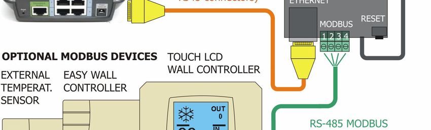
4.2.11. Wall controller
                                4.2.12. Weather station

                    5. THE FIRMWARE UPDATE

                         A - AUTOMATIC METHOD
                         5.1. Update preconditions
                         5.2. Update procedure – LAN scenario
                         5.3. Update procedure – WAN scenario

                         B - MANUAL METHOD
                         5.4. Copying of all files of new firmware
                         5.5. Reprogramming new firmware

                    6. ONLINECONTROLLER.EU SERVER
                         6.1. LOGIN page
                         6.2. Dashboard
                         6.3. List of air-conditioners
                         6.4. Adding of new device
                         6.5. Editing and delete device
                         6.6. Controlling of A/C units
                             6.6.1. Graphic controller with weather forecast
                             6.6.2. IT controller
                             6.6.3. Weekly timer
                         6.7. History
                         6.8. Editing user personal data
                         6.9. Adding, editing and deleting of another account
                         6.10. Logout

                    7. TECHNICAL PARAMETERS
                         7.1. Mechanical (parameters, weight, ...)
                         7.2. Electrical (Main voltage, input power, IP code...)
                         7.3. List of compatible indoor units

                    8. ACCESSORIES
                         8.1.   External Mounting Kit KKRPM01A
                         8.2.   WIFI Cable Pack KKRPW01A
                         8.3.   Easy Wall Controller KBRCS01A and Temperature sensor TS30
                         8.4.   Touch LCD Wall Controller KBRC01A
                         8.5.   Weather station P03/3

Online Controller KKRP01A - Service manual - 20120110                                       2
9. COMPLIANCE
                         9.1. Declaration of Conformity
                         9.2. LVD certificate
                         9.3. EMC certificate

                    10.        TECHNICAL SUPPORT – HOTLINE
                         10.1.    Frequently Asked Questions
                         10.2.    Trouble Shooting
                         10.3.    www.onlinecontroller.eu
                         10.4.    hotline: hotline@onlinecontroller.eu

Thanks for purchasing
Thank you for purchasing the adaptor Online Controller KKRP01A. We wish you a useful usage and enjoy a
comfortable control of your air-conditioning system. Please, read this manual carefully; then store it in a safe
place for the future use.

SAFETY PRECAUTIONS
       •    this device may be installed only by an authorized person for the installation and service of Daikin
            A/C units
       •    follow the safety instructions in the A/C unit manual
       •    never let the Online Controller get wet, this may cause an electrical shock or fire
       •    every time keep the instructions from operation manual to your air conditioner

Online Controller KKRP01A - Service manual - 20120110                                                     3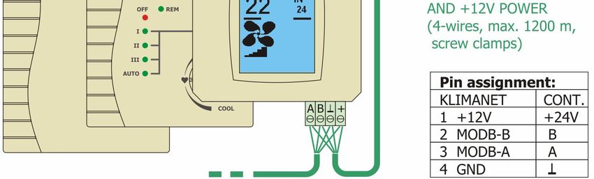
1. PRODUCT INTRODUCING

     1.1. About adaptor Online Controller KKRP01A
Online Controller KKRP01A is an auxiliary module, especially designed for Daikin air-conditioning units, which
enables to connect indoor split unit into IP network through Ethernet. User can easily monitor and control
the air-conditioner from remote place by using PC, PDA or Smart-Phone.

     1.2. Why Online Controller has been developed, the introducing of producer
Technological progress causes that the global network Internet is becoming an open platform, which enables
you to communicate comfortably with any technical equipments. Therefore KlimaNetOnline team has been
developing the device named Online Controller.
At the beginning there was a great idea to incorporate the air-conditioning systems into family of modern IT
technologies which allow you to keep the things “under control” anytime and anywhere you are.
KlimaNetOnline consortium is a team of ambitious people with a vision of making the life easier and more
comfortable and fulfilling. It is a group of engineers, who dedicated their lives to modern technologies
especially for A/C and IT.
There are three departments – hardware developing, server developing and department of technical support
and certification.

     1.3. Purpose of use, characteristics
Adaptor Online Controller KKRP01A is an electronic device designed for those Daikin air-conditioners which
have equipped the port S21 on their PCB. That port S21 is primarily designed for connecting of a wired
remote control Daikin BRC944 and Daikin KRP928. Online Controller KKRP01A is fully compatible with almost
all air-conditioner functions which are allowed by original wireless remote controller.
In addition it supports the facilities such as: web-server with JAVA, web-server without JAVA,
onlinecontroller-server client, SMS and e-mail control and fault management, SNMP agent (SNMP
monitoring and fault management), MODBUS for connecting accessories (f.e. LCD TOUCH…). As next it
includes the group mode function which supports central controlling up to 30 A/C units together at the same
time and online. It is also possible to back-up the A/C system with one more redundant unit and it can
monitor the temperature inside the room as well.

Online Controller KKRP01A - Service manual - 20120110                                                   4
1.4. Examples of use

                1. Single use – remote control via computer, PDA, cell phone

                                                          Picture No. 1

                2. Remote control via the www.onlinecontroller.eu server

                                     USERS                                Air-conditioners with
                                                                           adaptors KKRP01A
                                            SMS control

                                                                                 Internet

                                Mail            Mail
                                box

                                             Internet

                                                                                  Internet

                                              Internet

                                                                            Remote
                                                                            controller

                                                          Picture No. 2

Online Controller KKRP01A - Service manual - 20120110                                             5
3. Synchronous cooling of SENSITIVE TECHNOLOGIES with BACK-UP unit

                                                   OFFSET

                             PERIODICALLY alternating of the BACK-UP unit

                                                                OFFSET

                             MALFUNCTION of the unit causes the alternation immediately

                                                        Picture No. 3

                4. Synchronous control of MULTIPLE indoor units

              MASTER                   SLAVE            SLAVE                SLAVE        SLAVE

                        OC                      OC
                                                K               OC
                                                                 K                   OC
                                                                                      K           OC
                                                                                                   K

                                                                             Online        SINGLE
                                        OPENSPACE or BIG ROOM                               ROOM
                                                                            Controller

                                                        Picture No. 4

GROUP CONTROL ENABLES:
    • Synchronous control of multiple indoor units (up to 31), even if there are not attached to the same
       outdoor unit
    • One MASTER unit (equipped with master Online Controller) controls other units in the room
    • Possible to select parameters for grouping (ON/OFF, MODE …), other parameters will remain
       autonomously controlled (f.e. louvers, fan speed, etc.)

Online Controller KKRP01A - Service manual - 20120110                                                  6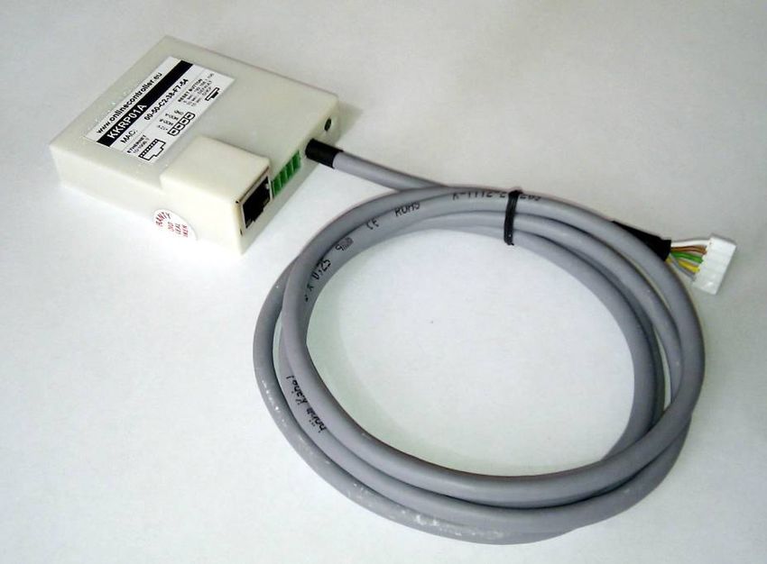
2. HARDWARE INSTALLATION

     2.1. Package content of Online Controller KKRP01A
The package includes:
     • Online Controller device with connected system cable 1,3 m
     • quick start manual
     • MAC address of adaptor KKRP01A is written on the nameplate on a plastic cover
     • this user manual is available on www.onlinecontroller.eu/downloads or on Daikin Extranet

                                                        Picture No. 5

     2.2. Description of the inputs/outputs
In the next picture there is described all inputs and outputs.

                   Ports:
                   out: 10377
                   in: 10378
                   http: 80 - default

                                                        Picture No. 6

Online Controller KKRP01A - Service manual - 20120110                                             7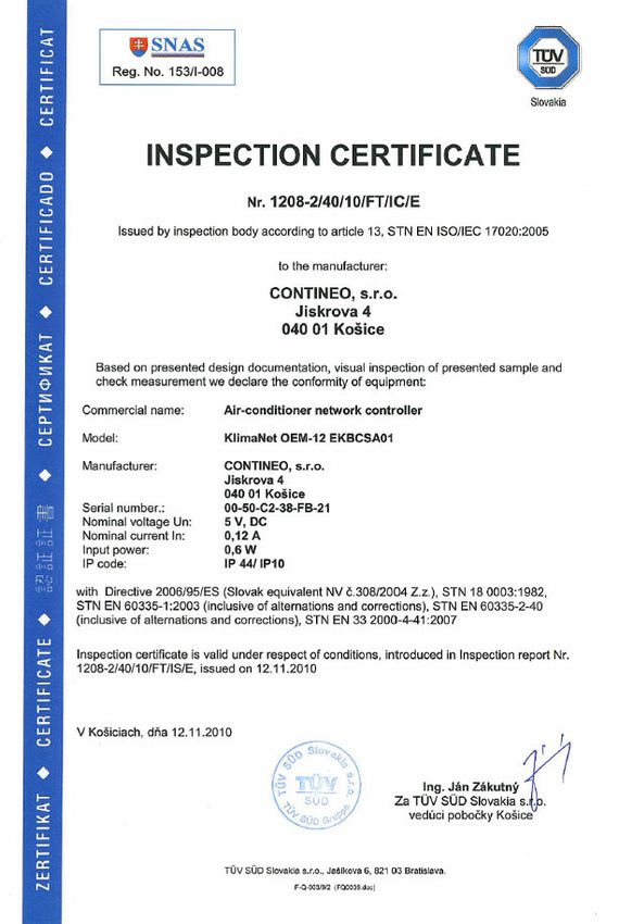
2.3. Installation of Online Controller KKRP01A
          2.3.1. Removing the cover panel
!       First of all you have to switch the A/C breaker OFF. You must ensure the power supply is really OFF.

Remove the cover panel and then the shield plate from electronic switch box. Please follow technical details
in corresponding A/C service manual!

            2.3.2. Find the suitable place for Online Controller
Online Controller is designed with plastic box with its dimension 60 x 64 x 20 mm. There are a lot of
possibilities, where to place Online Controller. For better illustration see picture No. 7. Put the adaptor
KKRP01A into suitable electric box. If the selected position exceeds the length of the original cable, it has to
be used the optional “External Mounting Kit KKRPM01A”. It will enable to increase the total length of the
system wiring up to 100m.

                                                        Picture No. 7

            2.3.3. Wiring connection
Please follow the schema in the picture No. 6.
     1. Find the connector S21 on the indoor unit PCB and plug the Online Controller system cable in.
     2. Connect Ethernet patch cord into Ethernet RJ-45 socket of Online Controller. The Ethernet patch
          cord should be installed only inside the building. (The Ethernet patch cord is not included. In many
          cases the patch cord or cable is a component part of customer LAN infrastructure). Second
          connector of the patch cord plug into free socket of the switch/router/PC or to LAN socket, for
          detailed description of LAN structure cases, read the chapter 3.1.
     3. If Touch LCD or Easy Wall Controller is used, then connect 4-pin cable into Modbus connector.

            2.3.4. Fixing and closing
Fix Online Controller and all cables at the selected place, use some binders. The cables should be kept
properly.

        Close the shield plate of electronic unit and mount unit cover panel.
!       Switch the breaker ON. The power supply can be turned ON.

Online Controller KKRP01A - Service manual - 20120110                                                     8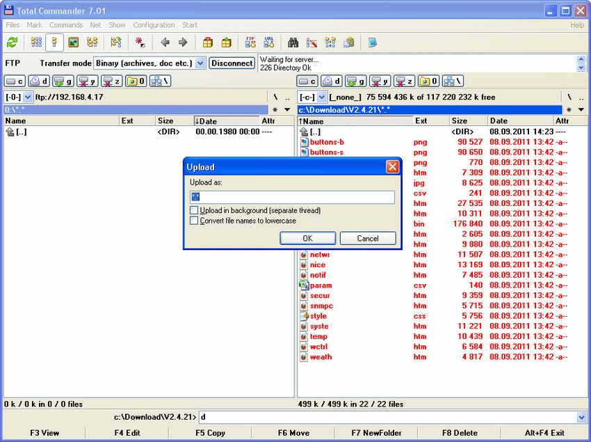
3. ONLINE CONTROLLER - CONFIGURATION

     3.1. Typical CASES of LAN structure with Online Controller KKRP01A
  I. STANDARD
          There is a LAN structure with integrated router or gateway, one or more computers connected in
          and one free LAN port at least is available.
          Procedure:
          Add A/C unit equipped with adaptor KKRP01A to LAN – plug second end of the controller’s patch
          cord into free socket of the router or into LAN socket on the wall.
          It is recommended to use static IP address for adaptor (read chapter 3.3).
          Example: residential house or flat…

 II. NO ROUTER
          There is only one computer connected directly to Internet.
          Procedure:
          Buy and install router, plug computer to router’s LAN port and plug router’s WAN port to Internet.
          Configure the router for active connection to Internet. Previous computer’s LAN setting must by
          copied to router’s WAN settings - follow install manual.
          Or buy and install GSM router and obtain the SIM CARD for data communication from your GSM
          provider. Connect computer to GSM router and configure it – follow its instruction manual.
          Add A/C unit equipped with adaptor KKRP01A to LAN – plug second end of the controller’s patch
          cord into free socket of the router.
          It is recommended to use static IP address for adaptor (read chapter 3.3).
          Example: residential house or flat…

III. NO ROUTER and NO COMPUTER
          There is no router and usually no computer.
          Procedure:
          Buy and install GSM router and obtain the SIM CARD for data communication from your GSM
          provider. Connect computer to GSM router and configure it – follow its instruction manual.
          Add A/C unit equipped with adaptor KKRP01A to LAN – plug second end of the controller’s patch
          cord into free socket of GSM router.
          It is recommended to use static IP address for adaptor (read chapter 3.3).
          Example: cottage, storage house…

IV. NO FREE LAN PORT
          There is a LAN structure with integrated router or gateway, more computers and other IP devices are
          connected in, but no free LAN port is available.
          Procedure:
          It is necessary to enlarge LAN structure – add new switch (f.e. 5-ports or more) into LAN. New free
          LAN ports will be available.
          Add A/C unit equipped with Online Controller to LAN – plug second end of the controller’s patch
          cord into free socket of the router, switch or into LAN socket on the wall.
          It is recommended to use dynamic IP address for adaptor KKRP01A (read chapter 3.4).
          Example: house with more computers; commercial house…

Online Controller KKRP01A - Service manual - 20120110                                                  9
V. A/C EXISTS YET
There is a LAN structure with integrated router or gateway, more computers and others IP devices
are in, some LAN ports are available.
Procedure:
It is not necessary to enlarge LAN structure, because there are some free LAN ports available.
Add next A/C unit equipped with adaptor KKRP01A to LAN – plug second end of the adaptor’s patch
cord into free socket of the router, switch or into LAN socket on the wall.
It is recommended to use dynamic IP address for adaptor KKRP01A (read chapter 3.4) and it is
possible to use the application IP-searcher for easier configuration of all adaptors KKRP01A at the
same network range.
Example: house with more computers; commercial house, bigger company, open spaces…
3.2. RESET
Perhaps In some cases (for example when IP address of Online
Controller is forgotten) there will be probably necessary to restore
the network settings of Online Controller to default values. For
these cases use RESET button embedded in PCB of controller (see
red arrow in the picture No. 8).
1. Reset network settings to default values
Reset the IP address, subnet mask and gateway IP to default values.
Procedure:
a) Power supply is ON. Picture No. 8
b) Push and hold the RESET button for 5 seconds (until yellow LED
on Ethernet connector flashes once). Then release the button.
Network settings after reset:
IP address of KKRP01A: 192.168.1.100
Subnet mask: 255.255.255.0
Gateway IP address: 192.168.1.1
2. Reset all settings of Online Controller to default values
Reset all controller’s settings include network settings (see above) and IP address of DNS to default values.
Procedure:
a) Power supply is ON.
b) Push and hold the RESET button for 10 seconds (until yellow LED on Ethernet connector flashes twice).
Then release the button.
c) Then turn OFF Online Controller and then turn ON (disconnect and connect the system cable back from
connector S21 or switch the A/C breaker OFF and ON (NOT only ON/OFF button on A/C front panel)).
Network settings after reset are default (see above), DNS IPs are set to 192.168.1.1. Name of air-conditioner
is set to default value and other parameters are erased.
Online Controller KKRP01A - Service manual - 20120110 103. Automatically assign the IP address (DHCP enable) and enable the communication with onlinecontroller.eu
server
This setting allows the user to set up network parameters of controller easier. “DHCP enable mode” is
switched ON and at once its communication to server onlinecontroller.eu will be switched ON as well. Other
parameters keep the previous values. This causes, that the network settings will be automatically obtained
from DHCP server (LAN network with active DHCP server is essential) and Online Controller will
communicate with onlinecontroller.eu server for its easy installation and configuration via server (active
internet connection is essential), read the chapter 3.4.
Procedure:
a) Power supply is ON.
b) Push and hold the RESET button for 15 seconds (yellow LED on Ethernet connector flashes three times).
Then release the button.
4. System Self-Test
The system test process will be activated – for service using only.
Procedure: DO NOT USE!!!
If RESET button is pushed for 20 seconds (yellow LED on Ethernet connector flash four times), then Self-Test
procedure is started. This option is for service using only. It is necessary to switch OFF and switch ON the
power supply of Online Controller to get him back to common state.
3.3. Configuration with static IP address
The main information about LAN infrastructure must be known - IP network setup information:
- Fixed IP address which should be assigned for Online Controller (for example 192.168.3.228)
- Subnet Mask (for example 255.255.255.0)
- Gateway (for example 192.168.3.254)
- DNS server IP address (for example 192.168.5.101)
- Onlinecontroller server IP address or domain (for example www.onlinecontroller.eu or
www.klimanetonline.com)
Please contact your or customer network administrator for this information. The IP address of Online
! Controller must be different and unique for each device in a network even printers and others
computers. Otherwise it will cause the network conflict and those devices will be inaccessible.
1. Check the connection of Online Controller system cable. LAN cable (Ethernet patch cord) must be plug in
Online Controller LAN socket, see picture No. 6.
Plug the second end of LAN cable directly to your computer and turn the computer on. Be sure that this
LAN connection is active – the LEDs on computer LAN socket are flashing or lighting. If not, then plug off
and on the both cables again.
2. Default IP address of Online Controller (first configuration from factory) is 192.168.1.100, subnet
mask is 255.255.255.0 and gateway’s IP is 192.168.1.1. Default http is set to 80.
Whatever administrator forgot the IP address of Online Controller, it would be set back to default
value by pushing the RESET button (read chapter 3.2. RESET, paragraph 1 or 2).
Online Controller KKRP01A - Service manual - 20120110 113. Set-up the computer network settings:
Go to Start Menu – Control Panel – Network Connections, right-click with mouse on Local area
Connection icon and left-click on Properties at the bottom of menu. In bookmarker “General” find the
Internet Protocol (TCP/IP) in a list and click on it and the press on Properties button under the list. The
Internet Protocol Properties window will open. Please, remember its current IP settings. Next, set the
new ones on your computer Ethernet Card manually; see picture No. 9.
1. Fix IP address: 192.168.1.101
2. Mask IP address: 255.255.255.0
3. Gateway IP address: 192.168.1.1
Picture No. 9
Start your favourite web browser (f.e. Internet Explorer, Mozilla
Firefox, Google Chrome…)
Type the IP address of Online Controller into address bar of web
browser and press ENTER. The Simple controller screen will be loaded
(see picture No. 11). Click on SETUP MENU button. In first step, the
LOGIN SCREEN will appear (see picture No. 10).
Type the login name
and password for
administrator level
(default settings for
both is admin) and click
on LOGIN button.
If login name and password is
correct, the SETUP will be
open.
Choose the Network Picture No. 10
bookmarker and set new IP
parameters. For detailed Picture No. 11
instructions read chapter 4.2 and 4.2.4 and 3.2.
Online Controller KKRP01A - Service manual - 20120110 12If the IP parameters of Online Controller is according to customer LAN parameters, drag out the patch from
computer and connect it to LAN (into switch or into Ethernet socket on the wall).
Set back previous settings of computer LAN card. At that moment, it is possible to monitor and
control Online Controller and air-conditioner via PC. Type the new IP address onto address bar of
web-browser. The Simple control screen should be loaded (see picture No. 11).
3.4. Configuration with dynamic IP address
The main information about LAN infrastructure might not be known, but active Internet connection is
! required.
1. Press and hold the RESET button for 15 seconds (yellow LED on Ethernet connector flashes three times).
Then release the button. The Online Controller will be switched to “DHCP enable mode” and at once its
communication to server will be switched on as well. For detailed instruction, read chapter 3.2 RESET,
paragraph 3.
The router, firewall and/or gateway must have opened the port 10377 for transmitting packets and
! port 10378 for incoming packets.
2. Open your web browser (f.e. Internet Explorer, Mozilla Firefox, Google Chrome…) and type the IP address
or domain of server: www.onlinecontroller.eu (respectively www.klimanetonline.com) into address bar.
Login page will be loaded (see in the picture No. 41, for detailed instruction, read chapter 6.1). Write
down your username (generally e-mail), password and press SIGN IN button.
If your own account does not exist yet, ask your installer for creating it. Therefore the
onlinecontroller.eu server has got closed structure of account management; your installer is liable for
creating it.
3. Add your new adaptor KKRP01A to your account. (For detailed instruction, read chapter 6.4 Adding of
new device). At the bottom of second page of add-form, there is local IP address displayed (see in the
picture No. 45). If this device is already added, find its local IP address in device’s details in datagrid (for
detailed information, read the chapter 6.3 List of air-conditioners).
4. Open new tab or new window of your favourite web browser (f.e. Internet Explorer, Mozilla Firefox,
Google Chrome…) and type the IP address of Online Controller into address bar of web browser
and press ENTER. The Simple controller screen will be loaded (see picture No. 11).
Online Controller KKRP01A - Service manual - 20120110 134. AUTONOMOUS OPERATION
Online Controller and connected air-conditioning system can be monitored and controlled in two
different ways.
The first way is autonomous operation of Online Controller via its web-server which is equipped directly in
Controller. That condition does not need the connection to the Internet. The direct connection to any
computer is sufficient. It may be plugged into switch or router too.
The second way is the monitoring and controlling remotely through the Internet from the server
www.onlinecontroller.eu or www.klimanetonline.com.
The active connection to the Internet is essential and the router, firewall and/or gateway must have
! opened the port 10377 for transmitting packets and port 10378 for incoming packets.
4.1. Monitor & control function
4.1.1. Simple controller – without JAVA
To control or setup your air-conditioning system via web-browser it is needed to start any web-browser
(f.e. Internet Explorer, Mozilla Firefox, Google Chrome…).
Type the IP address of Online Controller (default IP address is 192.168.1.100) onto address bar of
web-browser. Simple control window will open (see it in the next picture) with security level – user
(default setting).
User access can control A/C system. Security levels will be discussed in chapter 4.2.3 Security.
The easy controller has been
developed for web-browser Name of logged user
without JAVA and for the
older computers or simply Room or air-conditioner name
for users who prefer easier
Go to LOGIN window
control panel.
In a first moment after ON/OFF selectbox
loading the simple panel, it MODE selectbox
shows current A/C settings.
The controlling of A/C SETPOINT selectbox
system is available by FAN SPEED selectbox
choosing a new parameter SWING FUNCTION selectbox
value from an appropriate
RESET TIMERS selectbox
list by simply clicking on
selectbox. SET CHANGES button
RELOAD button
Area of environment condition
SETUP MENU button
Link to graphic controller
Picture No. 12 Link to Onlinecontroller.eu server
Online Controller KKRP01A - Service manual - 20120110 14At first, set all parameters which have to be changed and then click on the SET button for confirming.
The new parameters will be set. Wait 3 seconds approximately a then press the RELOAD button for
reading the actual parameters again.
CONTROLS:
On/OFF – for switching the A/C ON or switching OFF
Mode – for choosing the A/C mode: AUTO, DRY, COOL, HEAT, FAN, HUMIDITY
Set Temp – for setting a required temperature: 18°C - 32°C (COOL), 10°C - 30°C (HEAT), 18°C - 30°C (AUTO)
Fan – for setting a required level of fan speed: *, **, ***, ****, *****, AUTO
Swing – for setting a required swing function: OFF, UP-DOWN
Timer – for resetting of Timer function, which were set via remote control
SET – button for confirmation all changes; after click on SET button, wait 3 seconds approximately,
the click on RELOAD button
RELOAD – the button which is used for reading current values of A/C parameters
MONITOR AREA:
Room – temperature in the room or value from addition sensors in °C; for detailed information read
the chapter 4.2.10. Temperatures
Outdoor – temperature of outdoor environment in °C (if the outdoor temperature sensor is connected);
for detailed information read the chapter 4.2.10. Temperatures
Status – communication status and errors
LINKS:
Login menu – for switching to login menu - login and logout of user
Setup menu – for entering the SETUP menu pages (only administrator level can enter to SETUP)
Onlinecontroller.eu – for entering to www.onlinecontroller.eu
Nice – for opening the graphic control panel with dynamic refreshing
4.1.2. LOGIN screen
For entering LOGIN window, click on LOGIN menu link. CONTROLLER
LOGIN screen will be loaded (picture No. 13).
For entering the SETUP, type the login name and password for
administrator level (default settings for both is admin) and click on
LOGIN button.
If login name and password is correct, the SETUP will be open.
It is suggested to change the password to avoid the unauthorized
using and then not to forget it.
Picture No. 13
4.1.3. Graphic controller - with JAVA
Open any web-browser (f.e. Internet Explorer, Mozilla Firefox, Google Chrome…) and type the IP address of
Online Controller with annex /nice at the end, f.e. http://192.168.1.100/nice.htm or click on the NICE link
in Simple panel (picture No. 12). The graphic control panel will be loaded (picture No. 14).
Names and functions of icons and buttons are described beside the display. Each icon is usually a button
simultaneously. When pressing those buttons, their current status should be changed; after two seconds the
Online Controller KKRP01A - Service manual - 20120110 15command sequence is sent into air-conditioner unit via Online Controller. After several second (typically 2s)
Online Controller waits for A/C response and then displays its current status again.
Link to LOGIN screen
Logged USER
AIR-CONDITIONER
NAME
ON/OFF button MODE button
TEMPERATURE ADJUST
buttons
SWING FUNCTION
button
FAN SPEED buttons
TEMPERATURE and
HUMIDITY INDICATOR SETUP button
Link to Onlinecontroller.eu server Link to simple controller
Picture No. 14
NAMES AND FUNCTION OF ICONS AND BUTTONS (Refer to picture No. 14 and No. 39)
Room, respectively air-condition name or ERROR indicator
• It can be changed in SETUP MENU.
ON/OFF button
• Press this button once to start operation.
Press once again to stop it.
OPERATION MODE button
• Press this button to change current mode of operation.
• The operation modes are changed in that order
cyclically.
Online Controller KKRP01A - Service manual - 20120110 16TEMPERATURE ADJUST buttons
• Press these buttons to adjust current Setpoint.
FAN SPEED buttons
• Press these buttons to change air flow rate setting.
SWING FUNCTION button
• Press the button to activate moving of horizontal
and vertical louvers in this order.
DISPLAY OF CURRENT INDOOR and OUTDOOR TEMPERATURE
(it depends of availability of external sensor)
SETUP button
• Press this button to enter SETUP MENU.
ERROR INDICATOR and BUTTON
ERROR
• When an error or malfunction occurs the ERROR icon flashes.
• Clicking on it causes appearing of pop-up window with Error (Status) message.
4.2. SETUP MENU
The SETUP MENU has been designed for setting up all of Online Controller‘s parameters. To enter SETUP
MENU, click on SETUP menu button in Simple or Graphic controller.
For entering the SETUP menu, there is administrator level required. For
detailed information about various access levels, read the chapter 4.2.3
Security.
If current access level is not administrative, the LOGIN screen will be opened
(picture No. 13). Then type the login name and password for administrative
level and click on LOGIN button. If entering data are correct, the SETUP MENU
will be opened (see picture No. 16).
LOGOUT button is situated at upper-right corner. Press it for logout the
administrative level; then the Simple control module will be opened (picture
No. 12).
4.2.1. Main MENU bar
On the left side of Settings page is main MENU bar (see picture No. 15). There
are ten bookmarkers for Online Controller settings. The first choice is a link for
Simple control module. The second one is a link for Graphic controller. Click
onto partition which you want to check and change. The current bookmarker
will be prompted with white colour.
Picture No. 15
Online Controller KKRP01A - Service manual - 20120110 174.2.2. System
Main MENU
LOGOUT button
Basic system data
Other settings
RESET button
DEFAULT settings button
Picture No. 16
In this Settings section there are the basic parameters.
Unit name is displayed at the head of control module (f.e. room or air-conditioner name) and top of SETUP
pages. It could be helpful for easy identification of particular air-conditioner.
Unit model is only for user information about air-conditioner type.
Controller field defines a type of adaptor and Firmware field defines its FW version. Both parameters are for
reading only.
Other settings:
• IR remote controller – the control via standard handy remote controller can be blocked. Sometimes,
the adjusting of Setpoint is not blocked, despite of blocking IR controlling. If you want to use the IR
remote controller, choose Enabled checkbox.
• HOME LEAVE function – this setting enables automatic monitor and prevents of decreasing of room
temperature under set value: 16°C, 14°C, 12°C, 10°C. If the room temperature reaches critical
temperature, then A/C unit is turn ON, switch mode to heating and set Setpoint onto 18°C. For
detailed description of HOME LEAVE function, read the A/C manual carefully.
Press the SET button for confirming.
Click on RESET button for simple resetting of Online Controller.
Click on DEFAULT settings button to set of default parameters of Online Controller:
KKRP01A’s IP address: 192.168.1.100
Subnet mask: 255.255.255.0
Gateway’s IP address: 192.168.1.1
DNS IP addresses: 192.168.1.1
Online Controller KKRP01A - Service manual - 20120110 184.2.3. Security
In this section there is a tool for changing passwords of three levels of Online Controller access (picture No. 17).
Viewer level: This level enables the user open Simple or Graphic module and to monitor all parameters of
A/C process. The parameters can not be changed – they are for reading only.
User level: This level enables the user open Simple or Graphic module and to change any parameters of air-
conditioning. User can control A/C system. Entrance the SETUP is not possible for user level (even viewer).
Admin level: This level is designed for full monitor and controls of the Online Controller, including of access
to the SETUP.
Default password for viewer and user level is empty - therefore user is logged in automatically. In
SETUP the Old password bar for viewer and user level is coloured by grey. Default name and
password for admin level is admin (both).
Generally the login names and passwords have to have minimum 4 characters.
Picture No. 17
4.2.4. Network
NETWORK section is designed for editing the parameters of LAN and Onlinecontroller.eu server (picture No.
18).
MAC address is physical address of each Online Controller, which must be unique. It can not be changed. It is
read only and coloured by grey.
Get IP from DHCP: choose this setting for obtaining the IP address for Online Controller automatically from
DHCP server. The active DHCP server in LAN is needed. If it doesn’t exist, you must choose the fixed IP
address.
IP address, Subnet mask, Default gateway, Default DNS 1, 2, 3 and HTTP TCP port settings can be changed
manually. It is assumed the basic network knowledge. For confirming the changes, please click on SET
button.
Online Controller KKRP01A - Service manual - 20120110 19Picture No. 18
Onlinecontroller.eu server settings are pre-defined to Disable Connect to server. The marker is
! Disable. Switch it to Enable, for connecting Online Controller to Onlinecontroller.eu server.
Onlinecontroller.eu server monitors A/C systems remotely via Internet. The active connection to the internet
is essential. For detailed information, read the chapter 6. Onlinecontroller.eu server.
IP address (or domain) is the address of Onlinecontroller.eu server.
StandBy check time is time period between two requests (time between two checkpoints - questions: What
is new? And the answer from server is: Nothing! And after this period, again: What is new?), when Online
Controller is passive – no changes after a time.
WakeUp check time is time period between two requests, in case that Online Controller is active – some
parameters were changed.
Owner password is checked, when Online Controller is registered to server by user. If it does not
correspond, Online Controller will not be assigned to user account (please read the chapter 6.4. Adding of
new device).
User password is reserved for future use.
4.2.5. SNMP
Simple Network Management Protocol (SNMP) is a set of protocols for managing complex networks. SNMP
works by sending messages, called protocol data units (PDUs) or traps, to different parts of network. SNMP-
Online Controller KKRP01A - Service manual - 20120110 20compliant devices, called agents (Online Controller), store data about themselves in Management
Information Bases (MIBs) and return this data to the SNMP requesters.
Online Controller supports SNMP v2. Online Controller is SNMP agent which can send traps (status
information) to SNMP servers. An SNMP community is the group that devices and management stations
running SNMP belong to. It helps to define where information is sent. The community name is used to
identify the group. A SNMP device or agent may belong to more than one SNMP community. It will not
respond to requests from management stations that do not belong to one of its communities.
Picture No. 19
SNMP parameters (picture No. 19):
Read community: default public
Write community: default public
For changing the passwords, type new ones into white fields and press the SET button.
Trap destination IP address 1 to 4 are IP addresses where SNMP trap messages are being sent.
For enabling the SNMP function, choose Enable checkbox and press SET button.
SNMP traps are defined in SETUP page Events configuration, for detailed description read the chapter
! 4.2.7 Events Configuration.
4.2.6. E-mail alerts
Online Controller supports e-mail alerts sending function by co-operation with SMTP (Simple Mail Transfer
Protocol) server. SMTP server has to be available. (Please contact administrator of LAN for more
information).
Parameters of e-mail alerts function (refer to picture No. 20):
SMTP server (IP address or domain) is IP address of SMTP server.
Domain of SMTP server will be detected automatically, after confirming its IP address.
Online Controller supports e-mails via SMTP server only through default port 25. Mail server has to be
! configured as standard email server. Online Controller does not support user authentication and SSL
protocol.
Online Controller KKRP01A - Service manual - 20120110 21Picture No. 20
e-Mail sending:
In this section there are four bars for setting up four e-mail addresses, where e-mail alerts are sent.
Type the Subject of e-mails.
For activation the e-mail function, switch the e-Mail sending into Enable checkbox. Confirm by SET
button.
E-mail messages are defined are defined in SETUP page Events configuration, for detailed description
! read the chapter 4.2.7 Events Configuration.
4.2.7. Events Configuration
Events configuration screen (picture No 21) is interconnected with SNMP and E-mail alerts settings. There
are defined the messages here for SNMP management and e-mails alerts function.
Event 1 to 8 config fields are designed for setup events. These forms of events are available:
airnotcom - Online Controller does not communicate with air-conditioner unit
airerr - Air-conditioner unit has some error
delta>(t) - the event is activated in following cases:
- mode COOL or AUTO (when A/C is COOLing): when room temperature is higher then Setpoint + value “t”
- mode HEAT or AUTO (when A/C is HEATing): when room temperature is lower then Setpoint - value “t”
srvnotcom - Online Controller does not communicate with Onlinecontroller.eu server longer than
2 minutes
Messages 1 to 8 are prepared for setup the text messages (text of trap message or text of e-mail message).
Example: For monitor correct connection of Online Controller with A/C unit, write into “Event 1 config” field
the text “airnotcom” and into “Message 1” field the message text, f.e. “My Online Controller DOES NOT
communicate with air-conditioner!”. Confirm with SET button.
! SNMP or E-mail alerts data must be set.
Online Controller KKRP01A - Service manual - 20120110 22Picture No. 21
4.2.8. Group mode – SYNCHRO and SWAP/BACK-UP
It has been designed for central operating of a group of air-conditioners, f.e. in open-spaces. Several Online
Controllers connected to LAN can be configured into a group. User controls master Online Controller only
(with IR remote controller, web or wall controller). Any change of master parameters causes changing the
slave parameters. But if some slave parameter had been changed (f.e. locally using IR remote), it would have
been set back to previously status automatically by master.
One Online Controller must be set as MASTER and the others of the group are set as SLAVES. It is
possible to select group parameters (ON/OFF, MODE …), other parameters will remain single
controlled (f.e. louvers, fan speed, etc). One master can control up to 30 slaves.
In the standard GROUP MODE all air-conditioners of the group operate at the same time with the same
parameters (grouped) than master (see picture No. 4). User can control parameters locally which are not set
as „group parameters“.
Enhanced operation BACK-UP and SWAP
In case, when uninterruptible cooling is required (typical application is cooling of the sensitive technologies,
f.e. server rooms), a couple of air-conditioners operate in one room and back-up or redundant operation is
needed. It means there is installed one more A/C indoor unit. This redundant A/C unit operates with higher
Setpoint than others. When cooling power is not sufficient and room temperature increases over standard
SETPOINT + OFFSET, then back-up unit starts cooling too.
After pre-defined period, back-up unit is shifted. And in case of failure of any A/C unit the shifting occurs
immediately. For better illustration, see picture No. 3.
Factory default setting of each Online Controller is single use – group mode is not active.
For activation the group mode, first of all it has to be selected the MASTER air-conditioner with master
Online Controller. Choose the Master option and press the SET button (see picture No. 22a).
Online Controller KKRP01A - Service manual - 20120110 23Picture No. 22a Then select group parameters, which will be copied to SLAVE controller and confirm with second SET button. Next choose standard (OFF) or BACK-UP mode (ON). If BACK-UP mode is set, define swap period and back-up offset [°C]. The SETPOINT of back-up unit will be increased by offset, it means, that back-up unit usually operates with higher Setpoint. Press the third SET button. List of Online Controllers in group represents all grouped Online Controllers with their current Setpoint and room temperature. Write down all SLAVE Online Controllers assign to this MASTER Controller. Confirm by clicking on fourth SET button below this scheduler. For user information there is also average room temperature and maximum difference of room temperature. If some slave unit has to be deleted, just erase its IP address and press SET button. Next step is to set all slaves. Open SETUP SLAVE Online Controller. Online Controller KKRP01A - Service manual - 20120110 24
Choose the Slave  option and confirm with SET button (picture No. 22b). In the next part of window is
displayed IP address and status of master Online Controller.

                                                        Picture No. 22b

Master lost parameters - in case of loss of connectivity between master and slave, these parameters are
copied to slave once. Then SLAVE Online Controller is temporary out of group linkage and it is possible to
control it locally. When connection with master is recovered, all grouped parameters are being copied to
slave controller again. Confirm with SET button.

            4.2.9. Modbus devices

            Picture No. 23

Online Controller KKRP01A - Service manual - 20120110                                              25
In this section (see picture No. 23) there is a tool for setting up of optional accessories connected onto
Modbus – Easy wall controller (EWC35), Touch LCD (TLCD70), Temperature sensor (TS30) and Weather
Station (P03/3). Each Modbus device has to have own binary address (Modbus address) and in the case of
connection of two or more Modbus devices to one Online Controller, this address must be unique for each
one.
It can be chosen one external controller for one Online Controller either Easy wall controller or Touch LCD.
Set its binary address and confirm with SET button. The current connectivity status is displayed online (OK
or FAIL).
Default binary addresses: Easy wall controller: 8 Touch LCD wall controller: 3
Temperature sensor: 5 Weather station: 13
4.2.10. Temperatures
Picture No. 24
Temperatures screen represents account of two temperatures, Room (indoor) temperature and Ambient
(outdoor) temperature, which are displayed in Simple controller (Room and Outdoor) and in Graphic
controller (IN and OUT).
Two temperatures are arithmetic average of temperatures which are selected with the checkboxes.
There are four room (indoor) temperatures to be checked (if appropriate accessories are connected): from
Indoor unit, Wall controller, temperature sensor 1, temperature sensor 2.
There are four ambient (outdoor) temperatures to be selected (if appropriate accessories are connected):
from Outdoor unit, Weather station, temperature sensor 1, temperature sensor 2.
Online Controller KKRP01A - Service manual - 20120110 264.2.11. Wall controller
Picture No. 25
After clicking on Wall controller bookmarker in Setup menu; Wall controller screen appears.
The Setpoint range setting enables to define the range of temperatures for heating mode and for cooling
mode for Easy Wall controller only (EWC35).
The Allow this modes only setting enables to define the modes that are possible to control via Touch LCD
controller (TLCD70) only.
4.2.12. Weather station
Picture No. 26
This screen is read only. If the Weather station is connected, the data are online. For detailed information
read the chapter 8.5. Weather Station P03/3.
Online Controller KKRP01A - Service manual - 20120110 275. THE FIRMWARE UPDATE
As the development process is permanently running, there always will be some improvements and new
firmware versions for Online Controller. It is recommended to download it and process the update
procedure. The new firmware usually contains new features or improved functionality. The last firmware is
available at our web-page www.onlinecontroller.eu/downloads or on Daikin Extranet.
A - AUTOMATIC METHOD
5.1. Update preconditions
1. Visual Basic Runtime Files are required. Visual Basic Runtime Files are in general components of Windows
or they can be downloaded from http://support.microsoft.com/kb/192461 and installed.
2. In the case of using Firewall on computer it is recommended to allow FTP (TCP ports 20 and 21) and
TELNET (TCP port 23) or simply switch your Firewall to Interactive mode which will ask you for allowance.
(Or the Firewall can be switched off for update period).
3. For WAN scenario, it is important to set up the router for remote access, read chapter 5.3. paragraph 1.
It is possible to perform Update from inside of LAN (Computer and Online Controller are both connected to
switch in Local Area Network– LAN scenario) or from WAN (Computer is somewhere in the Internet and
Online Controller is in Local Area Network – WAN scenario).
5.2. Update procedure – LAN scenario
The computer and Online Controller are in the same LAN (connected to the same switch see Picture No. 27
or directly connect through ethernet cable) and they have got the IP addresses from the same range. For
example:
The Computer IP address: 192.168.1.101 with subnet mask 255.255.255.0
Online Controller IP address: 192.168.1.100 with subnet mask 255.255.255.0 (default values)
For detailed information please read chapter 3.3. Configuration with static IP address.
Picture No. 27
Online Controller KKRP01A - Service manual - 20120110 281. Download the zip file ControllerUpdate vX.Y.Z.zip (X.Y.Z is a number of firmware version) from download
section of server and save it to the folder in computer. Unzip this file (see picture No. 28).
Picture No. 28
2. Start the Controllerupdate.exe (double-click on it). Online Controller update tool will be running (see
picture No. 29).
Picture No. 29
Online Controller KKRP01A - Service manual - 20120110 293. The administrator level is required. Type the Login, password and Online Controller’s IP address.
Login – Login name for administrator access to Online Controller (default Login: admin)
Password – Password for administrator access to Online Controller (default Password: admin)
Online Controller name or IP address – IP address of Online Controller (default IP address: 192.168.1.100)
FTP Port and CMD Port – let it in predefine value (FTP Port: 21, CMD Port: 23)
4. Then press Start Update button and the update process will start.
The update process usually takes about 3-7 minutes; it depends on the network conditions.
5. After successful updating process the following text of Progress info window is displayed at the top:
Update FINISHED, Online Controller will be restarted (see picture No. 30).
6. If something else is displayed, please check the connection of Online Controller and computer, check
update preconditions and start whole update procedure again.
Picture No. 30
5.3. Update procedure – WAN scenario
Computer is somewhere in Internet and Online Controller is in Local Area Network (LAN) with connectivity to
Internet. WAN (public) IP address should be static (or hostname). In the picture No. 31 is an example of
eventual WAN scenario.
The computer IP address (somewhere in Internet): 172.16.0.2
The public WAN IP address: 192.168.3.228 or hostname
KlimaNet IP address in LAN: 192.168.1.100 with subnet mask 255.255.255.0 (default values)
For detailed information please read chapter 3.3. Configuration with static IP address.
Online Controller KKRP01A - Service manual - 20120110 30Note: Public IP address 192.168.3.228 in this example is only laboratory IP address. For update process
! it has to be real public IP address which is provided by your Internet provider or it can be a hostname.
Picture No. 31
Picture No. 32
Online Controller KKRP01A - Service manual - 20120110 311. First of all you have to ensure, that the router/gateway is set up for remotely access to Online Controller
located inside. If not, you have to set it up for WAN access (FTP and TELNET). It is about setting up the
NAT parameters (port forwarding or Virtual Server – can be called different for more routers).
Enter the router setup pages (or ask for help the network administrator) and set up the port forwarding,
it could be similar than in the picture No. 32.
For Example:
FTP communication via port 1035 from WAN will be forwarded to FTP default port (21) of Online
Controller IP address in LAN.
TELNET (or CMD) communication via port 1036 from WAN will be forwarded to TELNET default port (23)
of Online Controller IP address in LAN.
2. Download the zip file ControllerUpdate vX.Y.Z.zip (X.Y.Z is a number of firmware version) from download
section of server and save it to the folder in computer. Unzip this file (see picture No. 28).
3. Double-click on controllerupdate.exe. Online Controller update process will be running (picture No. 29).
Picture No. 33
4. The administrator level is required. Type the Login, password and Online Controller’s IP address. See
picture No. 33:
Login – Login name for administrator access to Online Controller (default Login: admin)
Password – Password for administrator access to Online Controller (default Password: admin)
Online Controller name or IP address – The public WAN IP address of Online Controller’s LAN network or
hostname (192.168.3.228 is example only)
FTP Port and CMD Port – change it in accordance with your router settings – see next steps.
In our example there is FTP port: 1035 and CMD port: 1036
Online Controller KKRP01A - Service manual - 20120110 32Note: Port 1037 from WAN is forwarded to HTTP port (80) of Online Controller IP address in LAN. It is
! used for remote access to Online Controller.
5. Then press Start Update button and the update process will start.
The update process takes about 5-10 minutes.
6. After successful execution of update the following text at the top of Progress info is displayed:
Update FINISHED, Online Controller will be restarted (see picture No. 34).
Picture No. 34
If something else is displayed, please check the connection of Online Controller and computer, check update
preconditions and start whole update procedure again.
Online Controller KKRP01A - Service manual - 20120110 33B - MANUAL METHOD
Note: This is supplementary method of firmware update. Please, use it, if it is not
! possible from any reason to use primary method (application Firmware Updater)
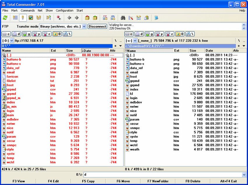
5.4. Copying all files of new firmware
1. Establish new FTP connection
Start Total Commander and choose the folder with new firmware. If it is packed, unzip all files. Go to upper
menu; choose Net and FTP New Connection. See next picture. Then type Online Controller IP address in your
LAN network.
Picture No. 35
Write name and password of admin level to field,
default is admin for both.
Confirm user name and password – press OK button.
The FTP connection will be established.
Online Controller KKRP01A - Service manual - 20120110 342. Delete all files in Online Controller
Delete all files in Online Controller by selecting all files and pressing DELETE button.
Confirm that – press OK.
Picture No. 36
3. Copying of new firmware files
Picture No. 37
Online Controller KKRP01A - Service manual - 20120110 35Select all files of new firmware and press F5 COPY button at lower menu.
Confirm – press OK.
4. Verifying of all files and their size
Picture No. 38
After copying, check all files and their size. If some files has not the same size, it is a need copy that again.
5. Disconnecting of FTP session
Verify copying process again. If it is not successful, repeat whole process again.
Then press the DISCONNECT button. It is not necessary to save this session... press No.
5.5. Reprogramming new firmware
1. Start command window
Go to Window’s START button (picture No. 39), then choose
the RUN and type cmd to the cell. Press OK button.
Picture No. 39
Online Controller KKRP01A - Service manual - 20120110 362. Open TELNET connection
Picture No. 40a
Write telnet IP_address of Online Controller and press Enter (picture No. 40a).
Picture No. 40b
Write the login and password. It is admin for both (picture No. 40b).
3. Start reprogramming process
Picture No. 40c
Online Controller KKRP01A - Service manual - 20120110 37Write reprog kl.bin gogo and press ENTER (picture No. 40c). The reprogramming process will start. Wait 2 minutes approximately. After reprogramming, the adaptor KKRP01A will be restarted automatically. 4. Close command window After time, you can close the command window, press upper-right crosslet. Online Controller has got new firmware and it is ready for use. Online Controller KKRP01A - Service manual - 20120110 38
6. ONLINECONTROLLER.EU SERVER

     6.1. LOGIN page
Open web browser (f.e. Internet Explorer version 7 or higher, Mozilla Firefox 3.11 or higher, Google Chrome
12.0 or higher…) and type www.onlinecontroller.eu into address bar.

               Picture No. 41

Login page will be loaded (picture No. 41). Write your username (generally e-mail), password and press
Sign in button.

        If your own account does not exist yet, ask your installer to create it. The onlinecontroller server has
        got closed structure of account management; therefore your installer is liable for creating it.

     6.2. Dashboard

                                                                                     UPPER MENU
                                                                                      Name of user
                                                                                      Role of user – Admin
                                                                                      User preferences
                                                                                      LOGOUT button

                                                                                      Name of server

                                                                                     MAIN MENU – for admin
                                                                                      Dashboard screen
                                                                                      List of air-conditioners
                                                                                      Tools
       Picture No. 42

Online Controller KKRP01A - Service manual - 20120110                                                    39
On Dashboard-screen is main place for monitor and control user-defined parameters, f.e. statistics and
shortcuts of functions. There will be other features supplemented here in a future.
Download – section for downloading the files
Air-conditioners represents list of A/C unit added to this account. For BASIC-PACKAGE there is limit of
number of units = 9. More units are available in EXTRA-PACKAGE and with Supervisor add-on
Tools – users and clients – adding, editing and deleting
Name of current user and other personal data can be edited in Tools\Users
User preferences – tool in upper menu for changing personal data and environment language
Logout button – push this button for logging out the account
6.3. List of air-conditioners
MAIN MENU
SELECTBOX for all devices
SELECTBOX for one device
POP-UP info line
CONTROL BUTTONS
Device
Weekly Timer
A/C control
History data
Search options - filter
All statuses
OK
KKRP01A comm
error
A/C comm error
Data line,
A/C error
Fan speed column
ANY error
Picture No. 43
MAIN MENU – switching between Dashboard, Download, Air-conditioners and Tools
POP-UP info line - informs user about current action which has been done, it drops out after a few seconds
CONTROL BUTTONS – are activated and deactivated automatically depending on choosing one or more
devices
Before any action with device, sign its selectbox at begin of data line
Weekly Timer – switch to the weekly programmer for air-conditioning
Gfx remote – graphic module with weather forecast for controlling one device
IT remote – simply module for controlling more devices simultaneously
History – of alerts, readings of room temperatures, commands and packet transfers
Search option – tool for filtering of devices by different states – ALL STATUSES, OK, CONTROLLER COMM
ERR, A/C COMM ERR, A/C ERR and ANY ERR
One data line of data-grid is designed for each device. There are the most important current values of
each device. Data are refreshed permanently every 10 seconds – the refreshing symbol blinks (see in
the picture No. 46). When the data is not available (because the communication error), the values
have got grey colour. Each column has to be sorted forward and downward for better statistics.
Online Controller KKRP01A - Service manual - 20120110 406.4. Adding of new device
Press Add device button. The add-form will appear (picture No. 44).
Picture No. 44
ALIAS NAME
GPS Picker
GPS coordinates
Indoor and Outdoor type
LOCAL IP ADDRESS
Picture No. 45
Online Controller KKRP01A - Service manual - 20120110 41Write MAC address of Controller, separate each two numbers. There are 3 separating
characters: , : - . Write owner password (default: owner). For changing the owner password, read detailed
information in chapter 4.2.4. Network.
Please read the LEGAL DISCLAIMER, sign the check-box and confirm by pressing Apply button. If the
authorization of new device is correct, the add process will continue (picture No 45).
In second page define the alias name. Place the device into map, move the GPS picker. Choose the type of
indoor and outdoor unit from the list. Only two characters are needed to type, and then it is possible to
choose from the list. Confirm all data by clicking on Apply button. The list of units will be updated (see
picture No. 43).
Local IP address of Online Controller is displayed below outdoor unit type.
6.5. Editing and delete device
SELECTBOX
Picture No. 46 Refreshing symbol
Picture No. 47
Online Controller KKRP01A - Service manual - 20120110 42Before any action (except from adding), the one or more devices have to be selected. Sign the appropriate
selectbox at begin of device line in data-grid (see in the picture No. 46).
For editing the basic parameters of device, press Edit device button. The second page of Add-form will
appear (picture No. 45). Make changes you want and confirm all data by clicking on Update button. The
record will be updated (picture No. 43). Or click on Cancel button for canceling the changes, no record will be
updated.
To delete any device, press Delete device button. The delete-screen will appear (picture No. 47).
6.6. Controlling of A/C units
6.6.1. Graphic controller with weather forecast
Select one device - sign the appropriate selectbox. Press the
Gfx Remote button. The graphic module will appear.
Background image is dynamic; it depends on current local
weather forecast.
Only one device can be controlled via graphic module at
! the same time.
Names and functions of icons and buttons are described in the
chapter 4.1.3 Graphic Controller. Left control part is the same
like graphic control module NICE.HTM included in Online
Controller. Each icon is usually a button
Control buttons
simultaneously. For controlling the A/C
unit, press the buttons within 2 seconds.
Weather forecast
After 2 seconds the new set of for 5 days
parameters is sent down to Online
Controller. Close module by clicking onto crosslet. Picture No. 48
6.6.2. IT controller
Select one or more devices - sign the
appropriate selectboxes at the
beginning of device lines in data-grid.
Press the IT Remote button. The IT
remote control module will appear.
The controls are similar than simply
control module EASY.HTM included in
Online Controller To change any A/C
parameters, select them and choose
their values. Confirm by clicking on Apply
button. After few seconds, the window
will be closed automatically.
Picture No. 49
Online Controller KKRP01A - Service manual - 20120110 43You can also read