USER MANUAL - MBRAINTRAIN
←
→
Page content transcription
If your browser does not render page correctly, please read the page content below
User Manual
Contents
1. Safety warnings............................................................................................. 1
2. Package content ........................................................................................... 4
3. Technical specifications ................................................................................ 5
4. SMARTING device description ...................................................................... 7
5. Connecting the Device to PC using BlueSoleil Bluetooth driver ................... 9
   5.1. Connecting SMARTING to PC ................................................................10
6. SMARTING Streamer standalone PC utility ................................................ 13
    6.1 Installation ............................................................................................13
    6.2 Starting up (The main window) ............................................................14
    6.3 Streaming the signal with 500 Hz sampling frequency and with the
        measure impedance on ref box selected .............................................16
    6.4 Streaming signal with 500 Hz sampling frequency and the impedances
        switched on ..........................................................................................18
    6.5 Streaming signals with 500 Hz sampling frequency and with the
        impedance measurements switched off ..............................................20
    6.6 Streaming signals with 250 Hz sampling frequency .............................22
    6.7 Signal display window ..........................................................................23
   6.8 Recording the EEG signals from SMARTING streamer ..........................25
       6.8.1 Recording the XDF file format ........................................................26
       6.8.2 Recording the BDF file format ........................................................29
   6.9 Closing the Signal display window and disconnecting the amplifier.....30
   6.10 Software update ..................................................................................30
7. Setting up the system ................................................................................. 33
8. SMARTING Android..................................................................................... 36
   8.1 Software installation layout...................................................................36

                          SMARTING User Manual – Release 18/05/2018                                          i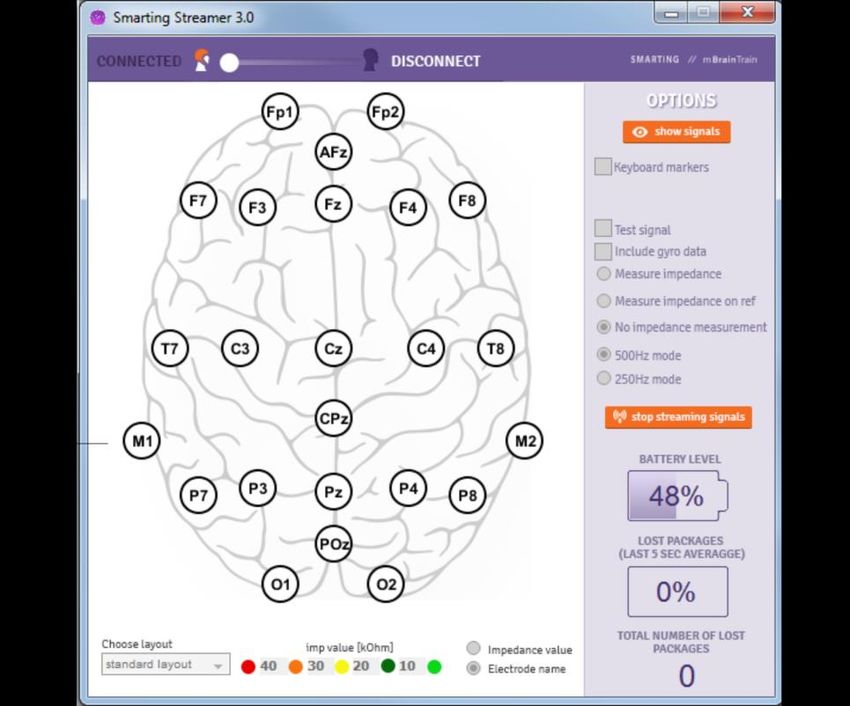
8.2 Connecting SMARTING ..........................................................................37
     8.3 Settings ..................................................................................................40
     8.4 Signal Display .........................................................................................48
     8.5 Recording the EEG signal .......................................................................50
     8.6 Disconnecting the Amplifier ..................................................................54
9. OpenViBE software and SMARTING driver for OpenViBE .......................... 56
10. External triggering .................................................................................... 60
     10.1 Procedure for sending triggers from OpenSesame ..............................63
     10.3 Enabling UDP triggering .......................................................................64
     10.4 Setting up SMARTING Android and SMARTING Streamer for listening
          triggers from OpenSesame ..................................................................69
     10.5 Procedure for offline triggers processing from OpenSesame ..............69
11. EEG Cap Maintenance .............................................................................. 70
12. Pin arrangement ....................................................................................... 71
13. Battery Instructions and Disposal ............................................................. 72
14. Custom electrode layouts ......................................................................... 73

ii                        SMARTING User Manual – Release 18/05/2018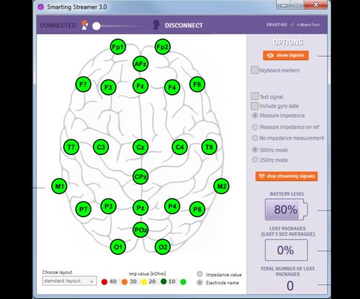
1. Safety warnings

Warning signs and examples of symbols shown here are mentioned so you
can use the device properly and reduce injury risks.

     Warning sign                                Meaning

                            Shows possibility of death or physical injury if the
                             instructions in this user manual are not properly
          Warning                                 followed.
                             Shows possibility of a physical injury or material
                            damage if the instructions in this user manual are
          Caution                        not properly followed.

                                 Sign examples

  The triangle sign    shows that
   you must be careful (including
  dangers and warnings). The
    explanation of the warning is
      adjacent to the figures.                      Fire Hazard sign.

    The crossed circle    sign
  demonstrates that something is
  not allowed. The explanation of
   this      sign is adjacent to the
                figures.                        Not allowed to unpack.

    The circle sign marks that
   something must be checked or
  should be taken into notice. The
 explanation of this sign is adjacent
         to the    figures .                        General Warning.

                    SMARTING User Manual – Release 18/05/2018                 1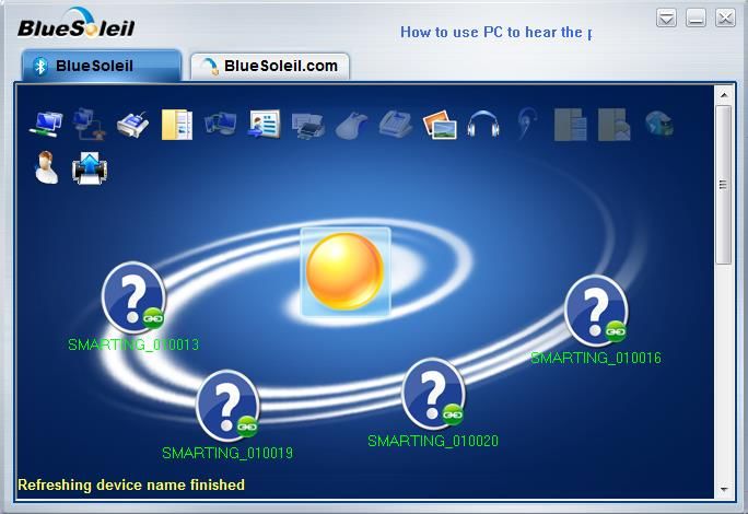
Caution
CAUTION: All General Safety Information that pertains to
equipment of other producers to which SMARTING device
is connected while charging or during signal acquisition,
apply here as well.
CAUTION: mBrainTrain products are NOT intended for
medical purposes or use in patient health care
environments.
CAUTION: mBrainTrain products are not designed for use
in inflammable or explosive environments.
WARNING: Do not connect your amplifier with the EEG cap
when the amplifier is being charged via your PC or Tablet.
CAUTION: It is advised to run the amplifier at room
temperature. If you are changing the current environment
of the amplifier, it is necessary to leave the amplifier off for
20-30 minutes before connecting it to any devices.
CAUTION: Amplifier’s battery is not replaceable and its
replacement could cause certain risks. Please do not try to
replace and/or disconnect the battery.

2                 SMARTING User Manual – Release 18/05/2018
Warning
WARNING: Use of controls, adjustments, procedures,
connections, or signal types other than those specified in
your documentation may result in exposure to shock,
electrical hazards, and/or mechanical hazards.
WARNING: Do not use your equipment in a wet
environment. Protect equipment from liquid intrusion. Do
not put the EEG cap on your head, if the cap is connected
to the amplifier and your hair is wet.
WARNING: Unit should be supplied by external power
supply evaluated according to IEC/EN 60950-1 and comply
with SELV requirements.
WARNING: Electrical shock or Fire Hazard. Do not try to
charge your amplifier with anything else but the USB
charger that you got with the device. This USB cable must
be connected by the USB port of the certified Lap top/PC
or certified mini USB charger.

WARNING: DO NOT try to open the amplifier casing. If it is
determined that you have opened the casing, your
warranty will no longer be valid.

WARNING: There is a possibility for external Bluetooth
interference. Please, minimize interference issues before
connecting to device.
WARNING: Risk of explosion or personal injury if the
amplifier is exposed to conducting materials, liquid, fire, or
heat (above 45oC).

                 SMARTING User Manual – Release 18/05/2018       3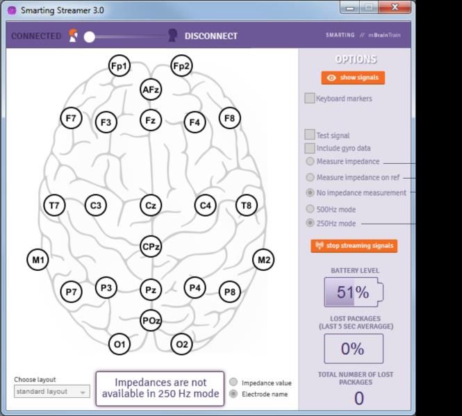
2. Package content

                      1                                         5

                            SMARTING EEG                              BlueSoleil's Blue-
                              Amplifier                             Tooth Dongle Class I

                              (s1b Version)                            (Type BS002)

                      2*                                        6
                              EasyCap's
                           customized EEG-
                               RBE caps                              USB Memory Stick
                                                                     with pre-installed
                                                                         software
                           (in different sizes and                     applications
                               with adapted
                             electrode layouts)

                      3*                                        7
                           EasyCap's Starter
                               SRC Kit
                                                                     Mini-USB Charger
                           (including several
                            consumables for                              (L0.25m)
                           the first couple of
                             testing rounds)

                      4*                                        8
                                                                      Documentation:
                            Mobile device                              User Manual
                           with pre-installed                         Warranty Card
                              SMARTING                                CE Certificate
                              application                             Declaration of
                                                                       Conformity

*Note that the exact package content structure in turns of existence and number of items
apart from SMARTING EEG amplifier and accompanying software is subject to specific offer
issued.

4                  SMARTING User Manual – Release 18/05/2018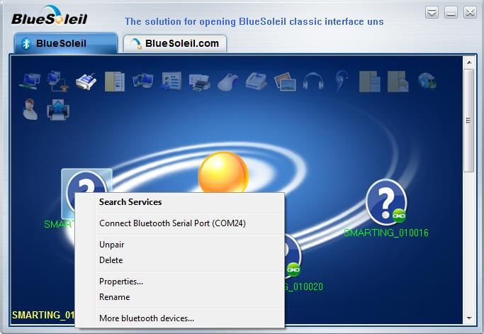
3. Technical specifications

                            General characteristics
Name                        SMARTING 24
No of channels              24
Reference                   One electrode is a reference (unipolar measurement)
Input impedance             500 MΩ
Input noise                 1 µV
Input range                 ±100 mV
CMMR                        >110 dB
Amplification               24
Gyroscope                   3D built in

                                  AD Conversion
Frequency                   250Hz or 500 Hz
Method                      Parallel sampling
Resolution                  24-bits
Bandwidth                   0-250 Hz
Anti-alias filter           Yes
Active ground               Yes

                             Communication type
Wireless communication      Bluetooth v2.1 + EDR
Max Bluetooth range         7-25 meters

                    SMARTING User Manual – Release 18/05/2018                5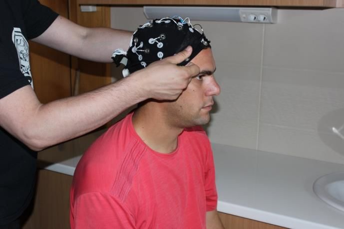
Power
Power                       Mini-USB rechargeable battery
Battery type                Li-Polymer, 560 mAh, 3.7 V
Operational time            ~ 4 hours

                                   Connectors
Electrode connectors        Cristek, IDC

                                   Dimensions
Physical size of the box    82x51x12 mm
Weight                      60 g

            Manufacturer:
            mBrainTrain LLC
            Ruzveltova 1a
            11 000 Belgrade, Serbia

               Carefully read the user manual

6                  SMARTING User Manual – Release 18/05/2018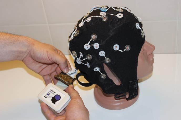
4. SMARTING device description
SMARTING (Figure 4.1) is intended for use as a biofeedback research
platform. The amplifier is located in a small casing with the physical
dimensions 82x51x12 mm. SMARTING is a mobile EEG amplifier that can be
used in unrestricted environment. If the device is moved to an environment
with a significant temperature drop/rise, leave the amplifier standing there
for 30 minutes, before turning it on. SMARTING must be used in normal
temperature and pressure conditions. The device must not be dropped, since
it may lead to malfunction.
1. The mini-USB port is intended only for charging the battery (marked by 1 in
Figure 4.1-left). The mini-USB port is located next to the red LED. SMARTING
device is not to be charged during recordings! Therefore, make sure the
device is removed from charging, before starting the experiments! Do not
use any other adapter for charging the battery! The device is intended to be
charged only by USB connector on PC.
Figure 4.1 The SMARTING
1 – USB connector; 2 – Red LED; 3 – IDC connector; 4 – Green LED
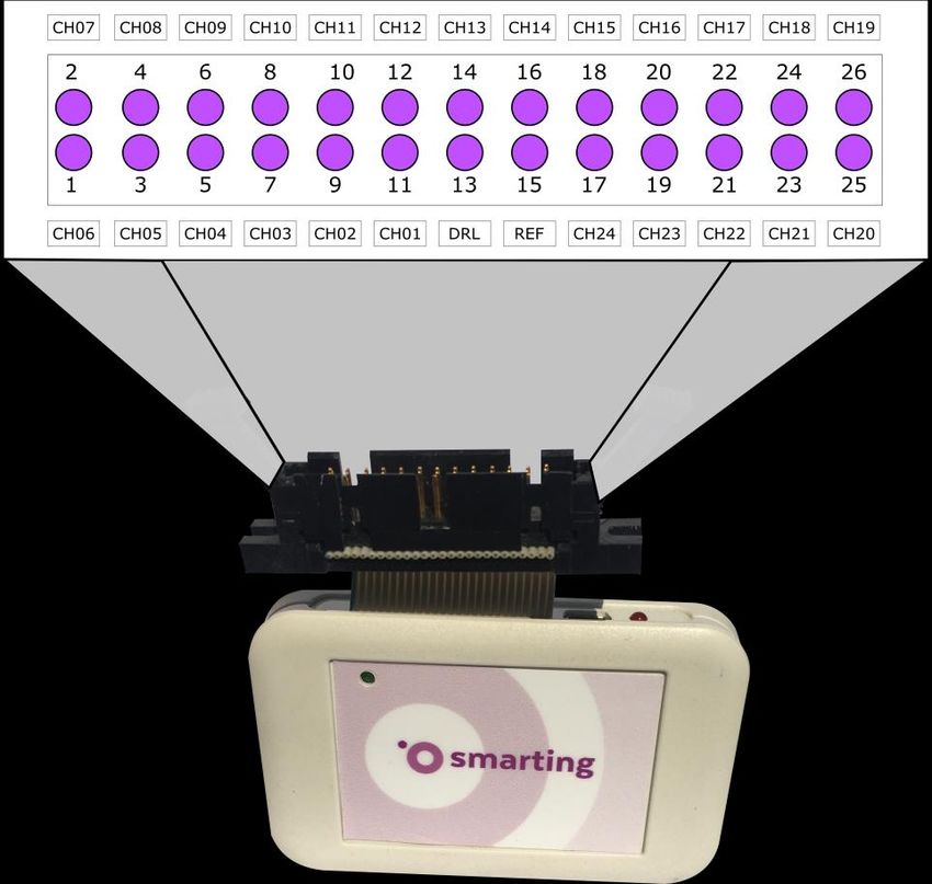
SMARTING User Manual – Release 18/05/2018 72. When SMARTING is connected to charging, the red LED will turn on (indicated by number 2, in the left part of Figure 4.1). When the amplifier is fully charged, the red light turns off. 3. The device contains a 26-pin connector (number 3 in Figure 4.1 - right). There are 24 pins for channel measurements, 1 pin for the reference electrode (REF), and 1 pin for the ground electrode (GND). This EEG connector connects to an EEG cap of your choice. We recommend using EEG caps made by EASYCAP. 4. The green LED light on Figure 4.1 right, marked by number 4 indicates whether the device is connected to your PC/Tablet or not. If the LED light is blinking, this means that the device is successfully connected. SMARTING device is approved for use in the EU. 8 SMARTING User Manual – Release 18/05/2018
5. Connecting the Device to PC using BlueSoleil Bluetooth driver

Before trying to connect the device to your PC/Tablet or make any
measurements, make sure that the amplifier is charged. Otherwise your
amplifier’s Bluetooth might not be visible to other devices. SMARTING can be
charged on any PC or any other portable device with the mini-USB port. The
charging process lasts approximately 4-5 hours.
To achieve the best performance with SMARTING device, it is highly desirable
to use the BlueSoleil Bluetooth driver. To do that, visit the web page
http://www.bluesoleil.com/products/S0001201005190001.html                     and
download the BlueSoleil 10 installation driver. The installation file can also be
found on the SMARTING USB dongle that arrived within the SMARTING
package (Chapter 2). The license for the driver is embedded in the BlueSoleil
dongle that arrived together with your SMARTING package (Figure 5.1).

                         Figure 5.1 The BlueSoleil dongle

After the installation has been downloaded, unpack the installation file. Click
the setup.exe file found within the install folder. Follow the on-screen
instructions to install the BlueSoleil Space. After the installation has been
finished, run BlueSoleil Space application from your desktop (Figure. 5.2).

                  SMARTING User Manual – Release 18/05/2018                 9
Figure 5.2 BlueSoleil Space application desktop icon 5.1. Connecting SMARTING to PC Double-click the orange circle (representing Sun - Figure 5.3) in the middle of the BlueSoleil space main window to search for all available devices. When the SMARTING device is detected, double click on the SMARTING icon that appears in the Bluesoleil space in order to search for services. When searching services is finished, click with the right mouse button on the device, and choose pair from the dropdown menu. After the device is paired, click again the right mouse button and choose Connect Bluetooth serial Port (COMxx) (Figure 5.4). The device icon will become green and the string appears connecting the device icon with the Sun icon (Figure 5.5). This indicates that the device has been successfully connected. It is important to memorize the Port Number for future use (this is the COMxx number in Figure 5.4). Now that the COM port has been assigned, you need to disconnect the device (by right mouse button clicking on the device and choosing Disconnect the Bluetooth serial Port (COMxx). The device is now ready to be used by other programs. BlueSoleil application can always be accessed from taskbar choosing the B icon (Figure 5.6). 10 SMARTING User Manual – Release 18/05/2018
Figure 5.3 Appearance of BlueSoleil Space application after finish of search for
                                    devices.

Figure 5.4 By right mouse clicking on the device, one can recheck the Port number.
                In this example the corresponding port number is 24.

                  SMARTING User Manual – Release 18/05/2018                      11
Figure 5.5 Connecting to device
Figure 5.6 Click the B sign to access BlueSoleil driver application
Bluetooth Troubleshooting
Problem Solution
PC cannot see SMARTING Please check whether the battery is
charged before trying to connect the
device.
Bluetooth asks for a password Type: 1111
12 SMARTING User Manual – Release 18/05/20186. SMARTING Streamer standalone PC utility
SMARTING Streamer represents a standalone utility for PC/Windows that
allows visualization and recording of EEG signals, checking and setting up
impedance values, registration and visualization of external triggers and
other functions that will be further explained.
6.1 Installation:
To install the SMARTING streamer application, please locate the installation
file (SmartingStreamer-setup.exe) on the USB flash that was delivered inside
the SMARTING package, or download the Smarting Streamer application
from the website (http://www.mbraintrain.com/support/) using the provided
Username and Password credentials located on the USB that came with the
package.
After launching the installation file, simply click on install and the application
will be installed on your PC.
Figure 6.1 Click the install button for installing the Smarting Streamer.
SMARTING User Manual – Release 18/05/2018 13After successful installation, Smarting Streamer app will automatically run
and the desktop shortcut icon will also be created. The streamer icon can also
be found in the Windows Start Menu.
6.2 Starting up (The main window):
Before starting the application, please make sure that all firewalls and
antivirus programs on your PC are disabled. It is recommended that other
CPU demanding applications (e.g. Google Chrome, Skype etc.) are switched
off.
Start the Smarting Streamer by double clicking the icon on your desktop or in
the Windows Start Menu. The window shown in figure 6.2 will appear. To
successfully connect your SMARTING device, please click the connect button,
marked with the number 1 in Figure 6.2.
Figure 6.2 The main window that appears when running the SMARTING Streamer.
Click on connect button (as marked with the number 1) in order to connect
SMARTING device to the streamer.
Upon this action, a window will pop-up (Figure 6.3) that allows you to select
the appropriate COM port (2), (You can find it in the BlueSoleil window while
14 SMARTING User Manual – Release 18/05/2018connecting SMARTING to your PC, Figure 5.4).
Optionally, it is possible to rename the EEG stream (3), in case you are
planning to record multiple EEG streams. Finally, by clicking the connect
button (4), SMARTING device will connect to the streamer.
Figure 6.3 The pop-up window in which the COM port can be selected (2).
Additionally, the EEG stream name (3) can be modified. The device connects to the
streamer by clicking the connect button (4).
Once SMARTING is connected the white slider (positioned in the upper-left
corner of the Streamer) slides leftwards and the head silhouette turns orange
(see Figure 6.4). At this point it is possible to choose the following options
from the main window (Figure 6.4):
- The Choose Layout menu (5) allows selecting the layout that
corresponds to the EEG cap that is used for recording (Standard,
Motor or cEEGrid). To load or create custom layouts refer to chapter
14;
- The color-coded impedance values can be setup by changing the
values inside the boxes (6);
SMARTING User Manual – Release 18/05/2018 15- The electrodes on the brain sketch can display either the impedance
values on each electrode position, or the electrode name, which is
user specified option (7)
- If the keyboard marker field (8) is checked, the keyboard stream will
become active and the keyboard presses can be visualized and
recorded in an XDF file.
- When the Test Signal box is checked (9), SMARTING device starts
generating and streaming test square signals. This option can be used
to check if the device is streaming correctly without connecting the
cap and a measurement subject – if signals are appearing and there
are no lost data packages, the connection quality is verified;
- To stream the gyroscope data together with the EEG data check the
Include gyro data box (10);
- To select the impedance values select the Measure impedance
button (11). Otherwise, select the No impedance measurement
button (13);
- Selecting the Measure impedance on Ref box (12) allows measuring
impedances on the reference electrode (explained in subchapter 6.3
and in Figure 6.5);
- The EEG data can be streamed with 500 Hz (14) or 250 Hz (15)
sampling frequency.
Note: If the data are streamed with 250Hz sampling frequency,
measuring the impedance values is not possible.
Upon setting up all the desired parameters, the EEG signal starts streaming
upon clicking the start streaming signals button (16) in the main window
(Figure 6.4).
16 SMARTING User Manual – Release 18/05/2018Figure 6.4 The main window - setting up of main parameters for the EEG streaming
6.3 Using the measure impedance on ref option
When mounting the EEG cap, we recommend to first check the impedance of
the reference electrode, since the reference electrode signal quality
influences the EEG signal quality on all other channels.
In order to do so, select the measure impedance on ref box (number 12 in
Figure 6.4), and tick the box 500 Hz mode number 14 in Figure 6.4). Once
these two boxes are selected and the button start streaming signals (number
16 in Figure 6.4) is clicked on, the reference electrode will appear in the
middle of the scalp sketch as shown in Figure 6.5 (17). At the same time, the
battery indicator will become active and it will show the current battery
status in percentages (18). Additionally, the box that shows the percentage of
lost packages (average in last 5 seconds of streaming) (19) and the counter of
the total number of lost packages, which shows the cumulative number of
lost packages during the signals streaming (20), as depicted in Figure 6.5.
Bear in mind that these measures should be close to zero.
SMARTING User Manual – Release 18/05/2018 17Figure 6.5 The main window when the measure impedance on ref and 500 Hz mode
boxes are selected. At this point it is possible to get the information on the battery
level (18), percentage of the lost packages in the last 5 seconds of streaming (19) as
well as for cumulative number of lost packages (20).
6.4 Using the measure impedance option
For measuring impedances, 500Hz sampling mode needs to be selected.
Once the signal streaming has started, the main window looks like the one
depicted in Figure 6.6. The electrode layout appears on the brain sketch in
the bottom-left panel of the streamer (17). The color coded or the numeric
impedance values (depending on what is selected under number 7 in Figure
6.4) will appear on the brain sketch.
At the same time, the battery indicator becomes active (18) and the battery
percentage is shown (Figure 6.6).
Also, the box that shows the percentage of lost packages (average in last 5
seconds of streaming) (19) and the counter of the total number of lost
packages (20) become active, as depicted in Figure 6.6.
18 SMARTING User Manual – Release 18/05/2018Figure 6.6 The streamer view when the signals are streaming with the impedance
measurement switched on
In order to visualize the signals, click the show signals button (21) (Figure
6.6), upon which the Signal display window is activated (Figure 6.7). If the
impedance measurements are selected, the color-coded impedance values
may be observed on the left side of the Signal display window, next to the
electrode names (22). The red line (23) is running in front of the signals and
denotes the most recent signal values. With this, it is possible to observe the
streamed signals in real-time.
More functionalities of the Signal display window will be presented in the
subchapter 6.7 (Signal display window).
SMARTING User Manual – Release 18/05/2018 19Figure 6.7 The Signal display window, in case when the impedance measurement is selected. The indication of the impedance values are presented in the left part of the Signal display window (22). The red line denotes the most recent samples (23). 6.5 Streaming signals with 500 Hz sampling frequency and with the impedance measurements switched off Upon mounting the cap and ensuring the proper electrode contacts, it is advisable to switch off continuous impedance measurement before proceeding to data visualization and acquisition, because this will reduce the high frequency noise components. If the box No impedance measurement (number 13 in Figure 6.4) is selected and the sampling frequency is set to 500 Hz (number 14 in Figure 6.4), the streamer main window looks like the one depicted in Figure 6.8. Two main differences between the cases measure impedance and No impedance measurement is that when impedance measurement is not selected, the electrode layout does not have the color codes (17) and it is not possible to observe impedance values, as it can be seen from Figure 6.8. 20 SMARTING User Manual – Release 18/05/2018
Figure 6.8 The main window interface when the impedances are disabled and the
                signal streaming is set to 500 Hz sampling frequency
When visualizing the signals in the condition when impedances are switched
off, the Signal display window does not visualize the color-codded impedance
values next to the electrode names (22), Figure 6.9.
Same as in Section 6.4, the red line runs in front of the signals (23).

                   SMARTING User Manual – Release 18/05/2018                21
Figure 6.9 The Signal display window, in the condition when impedances are
switched off. The impedance values are no longer visualized in the left part of the
Signal display window (22). The red line runs rightwards (23) denoting the most
recent samples.
6.6 Streaming signals with 250 Hz sampling frequency
When selecting the signal streaming with 250 Hz mode (15, in Figure 6.4), the
electrode impedance measurement is not enabled, i.e. if the box 15 is
checked, the Measure impedance (11) and Measure impedance on ref (12)
options in main window are no longer available (Figure 6.10). There is also a
note on the bottom of the streamer explaining it.
All the other functionalities remain the same as in case of the 500Hz sampling
rate and when the option No impedance measurement is selected (e.g. as in
Figure 6.8). The Signal display window is also identical to the one depicted in
Figure 6.9.
22 SMARTING User Manual – Release 18/05/2018Figure 6.10 The main window interface when the sampling frequency is set to 250 Hz
6.7 Signal display window
The click on the show signals button (number 21 from Figure 6.8) starts the
Signal display window, as depicted in Figure 6.11. The Signal display window
shows the raw EEG signals from each electrode that was selected in the main
window.
The Signal display window allows visualizing the EEG (also gyroscope) signals
in real time. The red line (23) runs in front of the signals and denotes the
most recent samples. As mentioned earlier, if the impedances are switched
on, the color coded circles, that represent the impedance values, will appear
in the left part of the Signal display window, next to the electrode names
(22).
SMARTING User Manual – Release 18/05/2018 23Figure 6.11 The Signal display window
The following options for signal visualization are available (Figure 6.11):
- The time scale (24):
o If set to auto, the time scale is automatically set;
o If set to manual, the user can manually change the
corresponding time scale by clicking + to increase or - to
decrease the time scale (25) – this controls the time window
being displayed;
o The time scale value is always shown (26).
- The Signal display window shows the filtered signals by default. The
filter function is designed by using the bandpass filter (0.1-40Hz).
However, this function can be disabled and the raw signals can be
visualized by clicking the filter off button (27). To observe the filtered
data again, click the same button again. Note: the signals are filtered
for visualization purposes only. When recording or streaming the
signals, the streamer stores and transmits the raw (non-filtered)
data regardless of the filtering option selected;
- The amplitude scale is also by default set to auto (28). In this way, the
scale is optimized to visualizing all the signals from each of the
channels. Alternatively, the user can set the scale to manual (28) and
adjust it by pressing + or - sign (29). The amplitude scale value is
always visible, while the Signal display window is on (30); For optimal
24 SMARTING User Manual – Release 18/05/2018visualization, manual values between 200 and 500 µV represent good
practices.
- For visual inspection, the user can pause the Signal display by
pressing the pause button (31). Note: by pressing the pause button,
the user just pauses the signal visualization, but not the signal
acquisition, streaming or recording;
- The EEG signals can be recorded directly by the streamer. The EEG
signals can be recorded in .BDF or .XDF file formats. By pressing the
record button (32), the Recording window pops-up, where the user
can choose the recording options (more on the signals recording will
be presented in the subsequent subchapter 6.8). The user can also
stop the recording by clicking the same button (32);
- The time length of the recorded file can be tracked during recording
(33);
- If any loss of packages occurs, the cumulative number of package loss
is continuously visualized (34).
6.8 Recording the EEG signals usng Smarting streamer
For recording the signals from SMARTING streamer, click on the recording
button (number 32 from Figure 6.11). Once the recording button is clicked on
the Recording window pops-up (Figure 6.12), where the user chooses if the
recording will be made in .XDF (by checking the XDF file – 35) or .BDF (by
checking the BDF file – 36) file format.
Figure 6.12 The Recording window overview
SMARTING User Manual – Release 18/05/2018 25Lab Streaming Layer (LSL) Compatibility: Lab Streaming Layer (LSL, https://github.com/sccn/labstreaminglayer) is an open-source, free platform that allows precise synchronous recordings of multiple signal streams coming from various sources. As such it is a very convenient approach that allows very precise triggering. All available trigger streams will be automatically displayed in the signal display window as vertical colored lines. Apart from precise triggering, SMARTING Streamer is fully compatible with other platforms that support the LSL protocol. It allows streaming signals into LSL and receiving other LSL streams from networked PCs in real-time. Moreover, with SMARTING streamer, it is possible to record all the available streams in single .XDF file. The name of the SMARTING stream that is sent to LSL is set up during the connecting phase (Figure 6.3). The name of the stream should be written in the Stream name text field. 6.8.1 Using the XDF file format Once the field XDF file is checked (annotation 35 in Figure 6.13) it is possible to choose from the list of available LSL streams (37). The list of available LSL streams is presented in the white box (37). The default stream that is readily available is the SMARTING stream (EEG from the Figure 6.13). The name of the stream appears first (38), while the streaming device name is written in the parentheses (39). If there are other devices that stream the signal from other networked PC, but those are not visible in the SMARTING streamer, click the update button (40). Upon clicking the button update, the other visible streams will appear in the white box (as in Figure 6.14). Note: If other streams are not visible upon updating the stream names, try disabling windows firewall by clicking the Control Panel->System and Security ->Windows Firewall->Turn Windows Firewall on or off->Turn off Windows Firewall. Tick the boxes in front of the streams to be recorded in the single .XDF file and the selected streams will be recorded simultaneously. 26 SMARTING User Manual – Release 18/05/2018
Figure 6.13 The Recording window overview, when the user selects the XDF file
                                    option
Note: In case of recording two SMARTING EEG streams, it is important to
provide different names to the EEG streams when connecting the
SMARTING device to Smarting Streamer (as described in Figure 6.3). As an
example, the EEG streams can be named EEG1, EEG2, etc., as shown in
Figure 6.14.
In order to choose the location and the file name of the .XDF file to be
recorded, choose either to manually enter the path and the filename in the
white box (41), to click the browse button (42), or keep the automatically
generated path and name (as in Figure 6.14).

Figure 6.14 The Recording window overview with multiple streams from multiple PCs

                  SMARTING User Manual – Release 18/05/2018                   27
If the browse button (42) is clicked, a new window choose storage folder will
pop-up in which the location of the file should be defined (the default
location is C:/Smarting Streamer recordings), as depicted in Figure 6.15.
Figure 6.15 The choose storage folder window overview
Once the recording folder is set, provide the filename and save the path by
clicking the Save button (Figure 6.15).
Figure 6.16 The Recording window – Start recording signals
In order to start recording a file, press the start recording button (43 in Figure
6.16). At this moment, the pop-up window withdraws and the Signal display
window appears.
28 SMARTING User Manual – Release 18/05/2018To stop the recording, press the recording button in the Signal display
window (denoted as number 32 in Figure 6.11).
6.8.2 Using the BDF file format
When selecting the BDF file option (36, Figure 6.17 the box with the available
streams becomes inactive since it is not possible to collect multiple streams
when recording a .BDF file format. However, .BDF format generally takes 25%
less disk space than if the same data is recorded in .XDF and is generally
supported by a larger number of post-processing software as a traditional
EEG file format.
The other steps are exactly the same as when recording the .XDF file format,
i.e. choose the path for the recording the .BDF file (either manually or by
clicking the button browse and navigate to the folder by GUI).
When the path is set and the filename is given, simply press the start
recording button.
To stop the recording, press the recording button in the Signal display
window (denoted as number 32 in Figure 6.11).
Figure 6.17 The Recording window overview, when the BDF file option is selected
SMARTING User Manual – Release 18/05/2018 296.9 Closing the Signal display window and disconnecting the amplifier
To close the display window, simply click hide signals button in the main
window, or close the Signal display window by clicking the x button in the top
right corner.
When the measurement is finished, click the disconnect button in the upper
left corner of the streamer’s main window (Figure 6.4) to put the device in
idle mode.
6.10 Software update
Once the updated version of the streamer is available, Smarting Streamer will
notify the user.
If the new update contains major modification, the update notifications will
pop-up prior to entering the streamer (as shown in Figure 6.18). The user will
be asked to choose one of the following options:
update the streamer;
get the new notification in 7 days;
To ignore the current update (by choosing the option never in
Figure 6.18), or
To cancel the notification and receive the update notification next
time when the streamer starts.
Figure 6.18 The update notification window
30 SMARTING User Manual – Release 18/05/2018If the user chooses the Update Now option from the update notification
window (Figure 6.18), the new streamer version will automatically be
downloaded and installed.
Note: It is necessary that your PC is connected to the Internet during the
auto update process.
If the user chooses the Remind me in 7 days option, the Update Notification
window will close and the streamer home window will appear with the
update notification (47), as shown in Figure 6.19. If the user clicks the update
button (47), the Update Notification window (Figure 6.18) will pop-up again.
Figure 6.19 The Update Notification that appears on the streamer home page, if new
major updates are available
If the user chooses the Never option, the Update Notification window will
close and the streamer home window will appear with the update
notification, as shown in Figure 6.19. If the user clicks the update button, the
update notification window (Figure 6.18) will pop-up again, and the user can
choose one of the available options.
SMARTING User Manual – Release 18/05/2018 31If the user chooses the Cancel option, the Update Notification window will
close and the streamer home window will appear with the update
notification, as shown in Figure 6.19. If the user clicks the update button, the
Update Notification window (Figure 6.18) will pop-up, and user can choose
one of the available options.
In case only a minor fix was made to the streamer, the Update Notification
window will not pop-up during the streamer initialization phase. However,
the update notification icon (orange colored) (48) will appear in the streamer
home window, as shown in Figure 6.20.
If the user clicks on the update icon, the Update Notification window will
pop-up (as depicted in the Figure 6.18 and the user can choose one of the
available options).
Figure 6.20 The update notification that appears on the streamer home page, if the
new minor updates are available
32 SMARTING User Manual – Release 18/05/20187. Setting up the system
This chapter covers the case of using SMARTING to record EEG signals.
Similarly one can record other physiological signals.
Note that the SMARTING amplifier is not compatible with other than passive
type of recording sensors (passive electrodes).
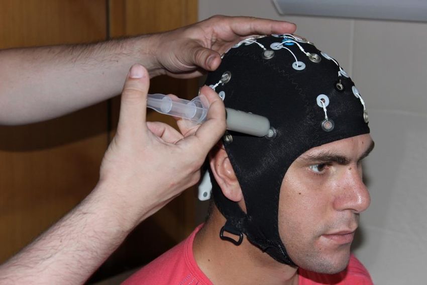
Figure 7.1 Connect the amplifier to the cap.
Figure 7.2 Position the cap on the subject's head.
SMARTING User Manual – Release 18/05/2018 33Figure 7.3 Carefully insert conductive gel to obtain high signal quality.
In order to obtain high quality EEG recordings, it is important to keep the
impedance values low, preferably around 5 kΩ. To check the impedance
values in real-time, use the SMARTING streamer described in Chapter 6.
1. Run the SMARTING Streamer application.
2. After connecting to the SMARTING device choose the appropriate
layout, as described in Chapter 6.1 (shown in Figure 6.5). Choose
impedance ranges for visualization of color indicators in the lower
left panel by simply clicking on the value and changing it to the
desired one. Click the Calculate button to accept the new settings
(Figure 6.6).
3. Select channels to record and click Start Streaming signals. Values of
electrode impedances should appear in the right panel, and the color
coded impedances are shown in the middle of the top panel (Figure
6.6).
34 SMARTING User Manual – Release 18/05/20184. After the impedances are appropriately set up, the experiment can
start. In order to avoid impedance measurements embedded in the
data (seen as a 125Hz noise):
a. Stop the streaming
b. Choose no impedance measurements
c. Restart streaming
Figure 7.4 The impedance values are shown either as color-codes or the actual
impedance values can be shown on the brain sketch (if impedance value option is
checked)
SMARTING User Manual – Release 18/05/2018 358 SMARTING Android
SMARTING Android is mBrainTrain's Android application for fully mobile EEG
recordings (Figure 8.1).
Figure 8.1 Android application for recording EEG data
mBrainTrain delivers the pre-installed software on a tested Android platform.
Software updates are handled by a user himself, in a simple and intuitive
manner. Note: Not all Android devices ensure reliable performance and it is
important that each platform is previously tested and verified by
mBrainTrain. Also, SMARTING Android app performs the best on Android
versions 7.1.2 and older.
The newest SMARTING Android software release can always be downloaded
from http://www.mbraintrain.com/support/
8.1 Software installation layout
To install the application, copy the SMARTINGAndroid.apk file to the
phone that will be used for recordings.
Find the file from a file browser on your phone, and click on it to
install the application. Prior to installation, make sure that
installation from unknown sources is allowed, in your phone settings.
If the previous version of the application is already installed, make
sure to uninstall it before proceeding with the software update.
36 SMARTING User Manual – Release 18/05/2018Note: The mobile phone included in the SMARTING package has already
pre-installed Android application.
8.2 Connecting SMARTING
After starting the SMARTING Android application, the home screen will
appear requesting to select the SMARTING device to connect to (Figure 8.2).
Note: For the best performance we recommend that the smartphone is in
the airplane mode, but with enabled Bluetooth communication.
Figure 8.2 Starting screen
If the device name that user seeks to connect to differ from the one denoted
with the A1 in Figure 8.2, select the arrow (A2) and the list of paired devices
will appear, as depicted in Figure 8.3.
SMARTING User Manual – Release 18/05/2018 37Figure 8.3 The list of paired devices
If the desired device does not appear in the device list, press the button not
this device (A3 in Figure 8.3), which opens a Bluetooth window showing the
list of paired devices (Figure 8.4).
Figure 8.4 The list of paired devices
The list of available devices is displayed bellow the paired devices. Scroll
down to choose the desired SMARTING amplifier (Figure 8.5).
38 SMARTING User Manual – Release 18/05/2018Figure 8.5 The list of available devices
When the device is found in the Available devices, select it and the device
should pair automatically to the phone. Once the device is paired, click on a
back button, and when returned to the home screen the paired devices will
appear in the choose device box (A1 in Figure 8.2). Press the (A1) button, the
device will connect to the smartphone, and the main window will appear, as
shown in Figure 8.6. One additional indication of a proper connection is the
blinking light on a Smarting device being connected.
Figure 8.6 The main window overview
SMARTING User Manual – Release 18/05/2018 398.3 Settings
It is advisable the check all the recording parameters, settings and enabled
sensor streams before initiating the recording. For this, the button settings
should be chosen (A4 in Figure 8.6). By clicking the settings button, the
settings menu appears (Figure 8.7) and user can choose between the
following options:
- Amplifier settings
o Disable or enable the impedances (A5);
o Enable or disable the test signal (A6).
o sampling frequency settings – 500 or 250 Hz (A7)
- Application settings
o Impedance settings – Modification of the color-coded
impedance threshold (A8)
o Touchscreen marker settings – enabling/disabling the sound
on touch markers and modification of touchscreen marker
names (A9);
o Recording settings (A10).
o LSL stream settings – choosing which data will be streamed
to local area network (LAN) over LSL protocol (A11); Note:
this option is available for 250Hz sampling frequency only.
Figure 8.7 The settings window overview
40 SMARTING User Manual – Release 18/05/20188.3.1 Impedance Settings
The color coded values are set by default to values 10, 20, 30 or 40 kΩ, and
above 40 kΩ as depicted in Figure 8.8a. However, the thresholds for color
coded values can be manually set by clicking on the desired color and
entering the new threshold value in pop-up window, as shown in Figure 8.8b.
(a) (b)
Figure 8.8 Impedance settings window
8.3.2 Touchscreen marker settings
In touch marker settings window, the user can enable/disable sound for
touch markers (A12 in Figure 8.9a). Furthermore, the user can change the
marker names by clicking on the marker that should be renamed and enter
the desired name in the pop-up window (as shown in Figure 8.9b). Note: the
marker names can be written only in XDF file format. In the BDF file format
the markers will appear in file with generic annotations, namely as 101,
102, 103, 104.
SMARTING User Manual – Release 18/05/2018 41(a) (b)
Figure 8.9 Touchscreen marker settings window
8.3.3 Recording settings
In the recording settings window the user can choose to record the data in
XDF or BDF file format (A13, Figure 8.10).
Figure 8.10 Recording settings window – choosing the recording file format
8.3.3.1 Inclusion of Motion sensors into recording file
Apart from choosing the file format, the user can also select to record the
data from motion sensor by enabling them (built in gyroscope – A14,
Smartphone’s accelerometers – A15, Smartphone GPS – A16 in Figure 8.11).
42 SMARTING User Manual – Release 18/05/2018Figure 8.11 Recording settings window – inclusion of other sensors and/or events for
synchronous recordings
8.3.3.2 Inclusion of external sensors
SMARTING android application allows the synchronous recording of EEG and
other supported sensors in XDF file format (only). External sensors are not
included in the default Smarting configuration, and are subject to specific
quote that should include them as items.
eSense sensors
SMARTING android application supports the electrodermal activity (EDA)
recordings made using the Mindfield® Biosystems eSense Skin Response
sensor. More information on eSense Skin response sensor:
https://www.mindfield.de/en/Biofeedback/Products/Mindfield%C2%AE-
eSense-Skin-Response.html
In order to record the galvanic skin response (GSR), plug in the eSense Skin
Response sensor into the smartphone’s audio jack. If the sensor is misplaced,
or not connected, a warning will appear in the signal display window (as
depicted in Figure 8.12a). In that case, ensure that the sensor is inserted
properly in to the audio jack, return to the signal display window, and
observe no warnings.
Another external sensor that can be used with SMARTING is the Mindfield®
Biosystems eSense temperature sensor. More information on temperature
SMARTING User Manual – Release 18/05/2018 43sensor can be found in following link:
https://www.mindfield.de/en/Biofeedback/Products/Mindfield%C2%AE-
eSense-Temperature.html
In order to record the body temperature, plug in the eSense Temperature
sensor into the smartphone’s audio jack. If the sensor is misplaced, or not
connected, a warning will appear in the signal display window (as depicted in
Figure 8.12b). In that case, ensure that the sensor is inserted properly in to
the audio jack, return to the signal display window, and observe no warnings.
(a) (b)
Figure 8.12 The pop-up window that appears if the eSense Skin Response (a) or
eSense Temperature sensor (b) is wrongly positioned in the smartphone’s audio jack
8.3.3.3 Embedding wireless triggers in EEG data
SMARTING android application allows wireless triggering either over LSL, or
UDP protocol.
There are currently two applications available for recording the event-related
potential (ERPs) experiments solely using smartphone, namely OpenSesame
(http://osdoc.cogsci.nl/) and Neurobs® Presentation
(https://www.neurobs.com/menu_presentation/menu_features/mobile).
OpenSesame uses the UDP protocol for embedding the trigger information in
both the BDF and XDF file format. The UDP triggers can be enabled by
choosing the option A19 – Figure 8.11.
Touchscreen triggers can be synchronously recorded with the EEG and other
sensors data, by enabling the touchscreen markers (option A20 – Figure
8.11). The touchscreen triggers can be recorded in both XDF and BDF file
format.
44 SMARTING User Manual – Release 18/05/2018Neurobs® Presentation uses the LSL protocol for sending the timestamps of
the triggers that can be recorded solely in the XDF file format (by enabling
option A21 – Figure 8.11).
8.3.4 Streaming settings
SMARTING android application allows streaming the data over LAN network,
by using the LSL protocol. In order to setup the streaming settings, click on
streaming settings (option A11 – Figure 8.7). Note, the LSL streaming over
LAN network is available only when sampling frequency is set to 250 Hz.
8.3.5 Recording settings
In order to allow the data streaming, enable stream data to LSL (A22 – Figure
8.13). Once the LSL data streaming is available, streaming data from motion
sensors is available and it can be enabled by selecting the wanted motion
sensors (Built-in Gyroscope – A23; Smartphone Accelerometers – A24; and
Smartphone GPS data – A25, depicted in Figure 8.13).
8.4 Main Window options
Once the desired settings are completed, the user can return to the main
page by clicking the back button at the bottom left corner of the application.
If the impedances are enabled, the electrode layout that appears over the
scalp sketch will show the impedance values in color codes (A26), and the
color coded values are presented in the bottom right corner of the
application (A27), as depicted in Figure 8.14.
In order to measure the impedance on the reference electrode, click the REF
button (A28 – Figure 8.14), and the reference electrode appears in the
middle of the scalp sketch. Impedance values are presented in the color
codes (A29 – Figure 8.15). To return to the electrode layout, press REF button
(A28 Figure 8.15).
SMARTING User Manual – Release 18/05/2018 45Figure 8.13 Streaming settings window The electrode layouts can be selected by pressing the menu button (as depicted by A30 in Figure 8.15), and the available layouts will appear in the drop down menu (A31 – Figure 8.15). There are two preinstalled layouts. However, the user can add custom layouts by adding them in the root folder of the cellphone’s internal memory. Upon adding the new layouts, they will appear in the drop down menu, after pressing the button (A30 – Figure 8.15). Figure 8.14 The overview of the main window, when the impedances are enabled If, for any reason, the electrodes should be switched off, the user can simply tap the particular electrode and the electrode will be marked as x . Once the electrode is switched off, it will no longer be available neither in Signal 46 SMARTING User Manual – Release 18/05/2018
display window, nor in the recorded file.

         Figure 8.15 The measure impedance on reference channel display
If impedances are disabled, the layout without color codes will appear in the
main screen (as in Figure 8.16).

  Figure 8.16 The electrode layouts can be chosen from the list of available layouts
To name the file that is to be recorded, click on the field A32 in Figure 8.17
and type the desired name in the pop-up keyboard. Upon naming the file, the
arrow pointing down should be pressed (A33 – Figure 8.17) in order to
remove the keyboard.

                   SMARTING User Manual – Release 18/05/2018                      47
Figure 8.17 Changing the filename
8.5 Signal Display
To visualize the signal, press the button (A34 – Figure 8.17) and the Signal
display window will appear (Figure 8.17).
Figure 8.18 Signal display window, when the impedances are enabled
The battery level of an amplifier is depicted with the vertical color bar at far
left side of the signal display window (A35).
48 SMARTING User Manual – Release 18/05/2018If the impedances are switched on, small color-coded circles (A36) will appear
next to the electrode names (A37). However, if the impedances are switched
off, no color-coded circles will appear (Figure 8.19).
Figure 8.19 Signal display window, when the impedances are disabled
The Signal display window can visualize up to seven channels at once. In
order to visualize the non-visible channels, slide vertically up or down.
The time scale is presented in the upper-left corner of the Signal display
window (A38 – Figure 8.18). The time can be adjusted by horizontal pinch-to-
zoom gesture (as shown in Figure 8.20a).
(a) (b)
Figure 8.20 Adjusting the time scale (a) and magnitude scale (b)
The filename given in the main screen (as in Figure 8.17) can be modified in
the Signal display window, by clicking at the area A39 in Figure 8.18.
The magnitude scale is depicted in the area A40 (Figure 8.18; By default, the
SMARTING User Manual – Release 18/05/2018 49magnitude scaling is automatic, however, the user can change it by vertical
pinch-to-zoom gesture (as depicted in Figure 8.20b)).
The signals can be paused for the visual inspection (A41 in Figure 8.18). Note:
The pause only freezes the visualization, the signals are still continuously
streamed and recorded.
8.6 Recording the EEG signal
The signals can be recorded by clicking the red record button (A42 in Figure
8.18). Once the recording has started, the pop-up window Recording preview
appears. In the recording preview window, one can check the filename,
sampling frequency, number of channels, whether motion data, other
sensors and/or events will be included in the recording. The recording
preview window is shown in Figure 8.21.
The timer, positioned next to the record button, becomes active (A43 in
Figure 8.22) when recording is started. Simultaneously, button for activating
touch markers appears (A45 in Figure 8.22) and if this button is clicked, touch
marker fields appear on the Signal display window as shown in Figure 8.22
(A46).
The press on the menu button (A46 in figure 8.23) activates the drop down
menu where user can switch off the visualization filter and autoscalling.
Figure 8.21 Recording preview window
50 SMARTING User Manual – Release 18/05/2018Figure 8.22 Activation of touch markers
To stop recording, click the record button once again (A42 in Figure 8.18) and
signal recording will cease. When the recording is stopped, an experiment
summary window pops-up (Figure 8.23) showing the following information
about completed recording:
- filename
- sampling frequency that was used during the recording
- number of events (Triggers)
- The percentage of lost packages for the whole duration of the
recording
- Number of Channel
SMARTING User Manual – Release 18/05/2018 51Figure 8.23 The Experiment summary window The Experiment summary window is closing upon clicking the button OK. Click the back button to return to the main screen. 8.6.1 Recording ERP experiment As mentioned in the Section 8.3.3.3 the SMARTING android application is capable of recording the ERP experiments, where the stimulus triggers are sent to the application and written into file wirelessly (either over UDP or LSL protocol). 8.6.1.1 Recording ERP experiments with the OpenSesame software OpenSesame experiments can be written in both available file formats (BDF and XDF). In order to send the markers over the UDP protocol, enable sending the events over UDP protocol in the recording settings page (as explained in the Section 8.3.3.3.). The next step is to give the desired filename, either in the main window (as shown in Figure 8.17), or in the signal display window (as explained in Figure 8.18). After naming the file, click on the recording button (A42, Figure 8.18). Please read carefully whether the UDP is enabled, in the recording preview window (Figure 8.21, under section events included). After selecting “OK” in the recording preview window, select the home button on the smartphone (return to the smartphone’s home screen) and enter the OpenSesame application. 52 SMARTING User Manual – Release 18/05/2018
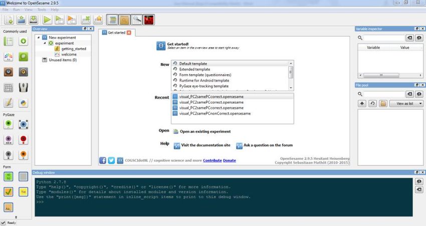
In the open sesame application, select and run the wanted experiment.
Upon experiment completion, return to the SMARTING application and
cease the recording (the information about recorded events will be
presented in the recording summary window – Figure 8.23).
NOTE: OpenSesame is the open-source software no longer actively
maintained for Android. The user opting for this tool should ensure the
reliability of the experiments first.

8.6.1.2 Recording ERP experiments with the Neurobs® Presentation
software
Neurobs® Presentation ERP experiments can be written in solely in the XDF
file format. In order to record the presentation experiments, enable
presentation in the recording settings window (as explained in the Section
8.3.3.3.).
Next step is to enter the Presentation application and select the desired
experiment from the experiment list (Figure 8.24a) and enter the experiment
main screen (Figure 8.24b) in order to initialize the presentation stream.
Note: do not run the experiment itself at this moment! After entering the
experiment, return to SMARTING application and name the recording file in
the main window (as shown in Figure 8.17). Upon naming the file, select the
signal display button (A34, Figure 8.16).

                   (a)                                         (b)

 Figure 8.24 The overview of the Presentation application; (a) – experiment list and
                         (b) – the experiment main screen
NOTE: If the SMARTING application experience difficulties in opening the
presentation stream, the following warning will pop-up: "Error in stream
opening – Please return to the main window and retry." If the warning

                   SMARTING User Manual – Release 18/05/2018                     53
appears, please return to the main window and re-enter the signal display window (A34, Figure 8.16). Upon entering the signal display window, click on the recording button (A42, Figure 8.18). Please read carefully whether the presentation is enabled, in the recording preview window (Figure 8.21, under section events included). After selecting “OK” in the recording preview window, return to the Presentation application and run the experiment. Upon experiment completion, return to the SMARTING application and cease the recording (the information about recorded events will be presented in the recording summary window – Figure 8.23). 8.7 Disconnecting the Amplifier In order to disconnect the amplifier from the application click the round button (A47 in Figure 8.25). Figure 8.25 Disconnecting the amplifier from the SMARTING android application When the disconnect button (A47) is pressed, the user is asked to confirm the disconnection of the device (Figure 8.26). Click the OK button to finally disconnect. 54 SMARTING User Manual – Release 18/05/2018
Figure 8.26 Disconnect the device window

SMARTING User Manual – Release 18/05/2018      55
9. OpenViBE software and SMARTING driver for OpenViBE

SMARTING device is supported by OpenViBE. OpenViBE is an open source
platform for brain computer interface and real-time neuroscience
experiments, and can be freely downloaded from http://openvibe.inria.fr.
We also provide an installer application on the USB stick that comes with the
SMARTING package. To install it from the USB, simply launch the installer
application file: openvibe-1.1.0-setup.exe and follow the on-screen
instructions, briefly described in the figures below.

                        Figure 9.1 Click the Next button

56                SMARTING User Manual – Release 18/05/2018
You can also read