User and installation manual - D5 NEXT - Aqua Computer
←
→
Page content transcription
If your browser does not render page correctly, please read the page content below
aquacomputer                                                          D5 NEXT

       User and installation manual

                                 D5 NEXT

                             aquasuite version X.17            ENGLISH: PAGE 1
                                                               DEUTSCH: SEITE 31
                            Current as of April 2020

All information contained in this manual is subject to change without prior notice.
                                 All rights reserved.

© 2019-2020               Aqua Computer GmbH & Co. KG                          -1-
                         Gelliehäuser Str. 1, 37130 Gleichen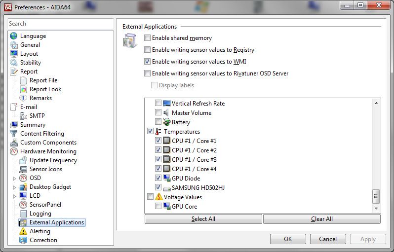
D5 NEXT                                                                   aquacomputer
Table of contents
1. Preface.........................................................................................4
2. Safety precautions.........................................................................4
3. Scope of delivery..........................................................................5
4. Assembly instructions.....................................................................5
        4.1. Detachable control unit, mounting options......................................5
        4.2. Installation to a top/cover or reservoir.............................................6
        4.3. Permitted pump orientations...........................................................6
5. Electrical connections....................................................................6
        5.1. Power Connector..........................................................................6
        5.2. Connector “USB”..........................................................................6
        5.3. Connector “Fan” for fan or flow sensor...........................................7
        5.4. Connector “Bus” for aquabus or RGBpx..........................................7
6. Operation....................................................................................8
        6.1. Operation via keys and display.......................................................8
        6.2. Configuration using USB connection...............................................8
7. aquasuite software........................................................................8
        7.1. Installation of the aquasuite software...............................................8
        7.2. Basic operation............................................................................9
        7.3. Symbols in the headlines................................................................9
8. Overview pages (aquasuite)...........................................................9
        8.1. Desktop mode............................................................................10
        8.2. Creating new overview pages and activating edit mode..................10
        8.3. Adding new elements..................................................................10
        8.4. Editing existing elements..............................................................10
        8.5. Values and names......................................................................10
        8.6. Detailed data elements................................................................11
        8.7. Log data chart............................................................................11
        8.8. User defined: Images, text, drawing elements.................................11
        8.9. Export and import of overview pages.............................................12
9. Data quick view and data log (aquasuite).....................................12
        9.1. Log settings................................................................................12
        9.2. Analyze data..............................................................................13
        9.3. Manual data export.....................................................................14
        9.4. Automatic data export.................................................................14
10. Pump configuration...................................................................14
        10.1. Pump mode power preset..........................................................14
        10.2. Pump mode temperature set point..............................................15
        10.3. Pump mode curve controller......................................................15
        10.4. Pump mode flow controller........................................................15
        10.5. General pump settings..............................................................15
-2-                              Aqua Computer GmbH & Co. KG                              © 2019-2020
                                Gelliehäuser Str. 1, 37130 Gleichen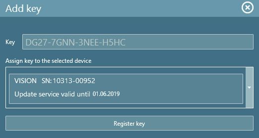
aquacomputer                                                                             D5 NEXT
        10.6. Pump behavior with aquabus connection to an aquaero...............16
11. Fan configuration.....................................................................16
        11.1. Fan mode power preset.............................................................16
        11.2. Fan mode temperature set point.................................................16
        11.3. Fan mode curve controller.........................................................16
        11.4. General fan settings..................................................................17
        11.5. Fan behavior with aquabus connection to an aquaero..................17
        11.6. Dual functionality – fan output or flow sensor input.......................17
12. RGBpx configuration.................................................................18
        12.1. Basic RGBpx settings.................................................................18
        12.2. LED mapping...........................................................................18
        12.3. Sound controlled effects.............................................................18
        12.4. AMBIENTpx effect.....................................................................18
13. Sensor configuration.................................................................19
        13.1. Water temperature sensor..........................................................19
        13.2. Options for flow rate measurement.............................................19
        13.3. Virtual flow sensor.....................................................................19
        13.4. Mechanical flow sensor.............................................................20
        13.5. Software temperature sensors.....................................................20
14. Alarm configuration..................................................................21
        14.1. Acoustic alarm and lighting........................................................21
        14.2. Alarm reporting and alarm limits................................................21
        14.3. System alarms..........................................................................22
15. Display configuration and information pages..............................22
        15.1. Display settings.........................................................................22
        15.2. Charts.....................................................................................23
        15.3. Display pages...........................................................................23
16. Profiles.....................................................................................23
        16.1. Manual profile selection............................................................23
        16.2. Automatic profile selection.........................................................23
        16.3. Profile configuration..................................................................23
17. System settings D5 NEXT...........................................................23
        17.1. Device information....................................................................23
        17.2. Factory defaults........................................................................24
        17.3. aquabus/RGBpx configuration...................................................24
        17.4. Firmware update and language selection (aquasuite only).............24
18. Playground (aquasuite)..............................................................24
        18.1. Virtual Software Sensors.............................................................24
        18.2. Global profiles.........................................................................25
        18.3. Hotkeys...................................................................................25
19. aquasuite web..........................................................................26
        19.1. Data export..............................................................................26

© 2019-2020                      Aqua Computer GmbH & Co. KG                                          -3-
                                Gelliehäuser Str. 1, 37130 Gleichen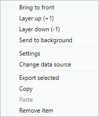
D5 NEXT aquacomputer
19.2. Data access.............................................................................26
19.3. Data import..............................................................................27
20. Basic settings (aquasuite)...........................................................27
20.1. Language................................................................................27
20.2. Reorder menu items..................................................................27
20.3. Units.......................................................................................27
20.4. Application start-up...................................................................27
20.5. Service administration...............................................................28
20.6. Audio and video.......................................................................28
20.7. Updates and update service.......................................................28
21. Technical details and care instructions........................................29
21.1. Technical details.......................................................................29
21.2. Restore factory defaults..............................................................29
21.3. Care instructions.......................................................................29
21.4. Waste disposal.........................................................................30
21.5. Contact Aqua Computer............................................................30
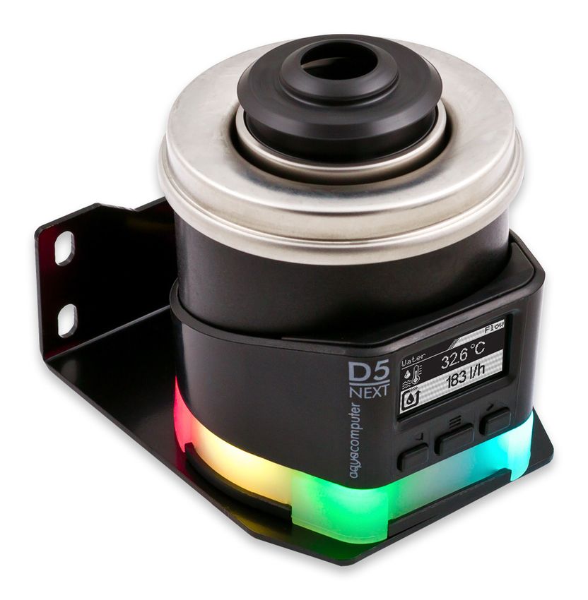
1. Preface
The D5 NEXT pump is built for longevity and to match the highest quality stan-
dards. It has been particularly designed for PC water cooling systems. The pump is
based on the Laing/Lowara/Xylem D5vario pump and the stainless steel top with
ceramic ball, the pump rotor and part of the electronics and housing are manu-
factured by Laing/Lowara/Xylem.
Laing D5 pumps are based on a shaftless spherical motor: The hemispherical ro-
tor/impeller unit sits on an ultra-hard, wear-resistant ceramic ball. Due to its self
adjusting properties, bearing play does not change even after prolonged use, the
pump keeps on running on a constantly low noise level.
In addition to the proven characteristics of the Laing D5 mechanics, the D5 NEXT
features outstanding monitoring and control options developed by Aqua Comput-
er: The D5 NEXT is equipped with with an integrated fan controller for PWM fans,
an USB interface as well as either an aquabus interface or a RGBpx effect con-
troller for up to 64 individually addressable LEDs. An OLED display can be used to
visualize current sensor readings or to configure the pump.
Considering the fast technical development, we reserve the right to perform alter-
ations to the products at any time. It therefore is possible that your product does
not correspond precisely to the descriptions or especially the illustrations in this
manual.
2. Safety precautions
The following safety precautions have to be observed at all times:
● Read this manual thoroughly and entirely!
-4- Aqua Computer GmbH & Co. KG © 2019-2020
Gelliehäuser Str. 1, 37130 Gleichenaquacomputer D5 NEXT
● Save your data onto suitable media before working on your hardware!
● The pump must not be placed under water!
● The pump controller on the rear end of the pump must not get in contact
with water!
● The pump may only be used inside a PC case!
● The pump is not a suction pump. Make sure the pump chamber is filled with
water prior to operation!
● The pump is not suited for dry operation!
● This product is not designed for use in life support appliances, devices, or
systems where malfunction of this product can reasonably be expected to re-
sult in personal injury. Aqua Computer GmbH & Co. KG customers using or
selling this product for use in such application do so at their own risk and
agree to fully indemnify Aqua Computer GmbH & Co. KG for any damages
resulting from such application!
3. Scope of delivery
The following scope of delivery applies to the retail version only, product code
41118:
● One D5 NEXT pump motor complete with detachable controller unit, sili-
cone damper (replacement part no. 94694) and mounting plate (replace-
ment part no. 94766)
● One internal USB cable (replacement part no. 53215)
● One mounting bracket, black (replacement part no. 94719)
● One silicone insert (replacement part no. 94695)
● Three screws M3 x 12 mm, countersunk head (replacement part no. 91149)
● Three washers M3 (replacement part no. 91019)
● Three hexagon nuts M3 (replacement part no. 91017)
● Four screws M4 x 8 mm (replacement part no. 91007)
● Four hexagon nuts M4 (replacement part no. 91053)
● One manual
4. Assembly instructions
4.1. Detachable control unit, mounting options
The controller unit of the pump can be removed by pulling it off the pump motor
unit in a straight line. Make sure that no power is supplied to the pump whenever
the controller unit is being removed from or re-attached to the pump motor unit!
The controller unit can only be attached to the pump motor unit in a given orienta-
tion. Do not use excessive force but re-check the orientation if you encounter
problems re-attaching the controller unit.
The pump may be installed into the PC case using the supplied silicone damper
and mounting plate, either to a level surface or – using the supplied 90° bracket –
© 2019-2020 Aqua Computer GmbH & Co. KG -5-
Gelliehäuser Str. 1, 37130 GleichenD5 NEXT aquacomputer
to a vertical surface. If these mounting options are not used, the silicone damper
of the pump can be replaced with a flat silicone insert.
Please note that all mounting options that make use of the silicone damper require
the pump to be installed vertically above the damper and are not designed to
withstand lateral stress or transportation of the PC!
4.2. Installation to a top/cover or reservoir
For operation of the pump, a compatible top/cover is required, alternatively the
pump may be installed directly to a compatible reservoir. In both cases, the pump
motor will be held in place by fixation rings to be slid over the pump. In order to
do so, detach the controller unit from the pump motor unit, fasten the pump motor
using the fixation ring and re-attach the controller unit.
4.3. Permitted pump orientations
During operation, the impeller of the pump must be directed upwards or to the
side relative to the controller unit. Operation with downwards oriented, “hanging”
impeller is not permitted!
5. Electrical connections
ATTENTION: Completely turn off your power supply or disconnect the mains pow-
er cord from the wall outlet before connecting or disconnecting any cables to/from
the device!
5.1. Power Connector
Connect a SATA power plug of your PC's power supply unit to this connector. Do
not use excessive force but double check the polarity of the plug if you are having
trouble to connect.
Pin assignment: Pin 1, 2, 3, 11: not connected
Pin 4, 5, 6, 10, 12: GND
Pin 7, 8, 9: 5 V DC
Pin 13, 14, 15: 12 V DC
5.2. Connector “USB”
This connector is used for USB communication with a PC. Connect to an internal
USB header of your motherboard. Take special care to make sure the pin align-
ment matches your motherboard! The USB interface is used for data exchange
with the PC and not required for pump operation.
The corresponding connector on the motherboard is usually
a 9 pin connector with two independent USB ports. Both
rows of 4/5 pins can be used to connect an USB device.
-6- Aqua Computer GmbH & Co. KG © 2019-2020
Gelliehäuser Str. 1, 37130 Gleichenaquacomputer D5 NEXT
The black wires (GND) are to be connected to the side of the missing pin, see pic-
ture with colored pin assignment.
Pin assignment: Pin 1: GND (black, optional)
Pin 2: GND (black)
Pin 3: D+ (green)
Pin 4: D- (white)
Pin 5: +5 V (red)
5.3. Connector “Fan” for fan or flow sensor
Depending on configuration, this connector can either be used as a PWM regulat-
ed fan output with speed signal processing or to connect a flow sensor. Simultane-
ous use of both functions is not possible!
Pin assignment: Pin 1: GND
Pin 2: 12 V / max. 25 W
Pin 3: Speed signal
Pin 4: PWM signal
Flow sensor and special interconnecting cable are optional accessories and not in-
cluded in delivery.
Compatible flow sensors:
● Flow sensor with 5.6 mm nozzle (53061)
● Flow sensor “high flow” (53068)
● Connection cable for flow sensor (53027, 53100)
5.4. Connector “Bus” for aquabus or RGBpx
Depending on configuration, this connector can either be used for communication
with other Aqua Computer devices or to connect RGBpx products (up to 90 ad-
dressable LEDs). Simultaneous use of both functions is not possible!
Compatible aquabus devices:
● aquaero 6 XT (53146, 53206, 53250, 53251, 53262, 53263)
● aquaero 6 PRO (53145, 53253)
● aquaero 6 LT (53234)
● aquaero 5 XT (53089, 53125, 53249)
● aquaero 5 PRO (53090, 53252)
● aquaero 5 LT (53095)
If the RGBpx product to be connected has more than one RGBpx connector, the
connector marked with the word “IN” must be used! Additional RGBpx products
may be connected to the “OUT” connector.
Compatible RGBpx products:
● RGBpx LED-Strip (53268, 53269, 53270)
● RGBpx lighting set (53271, 53272)
● RGBpx Splitty4 (53267)
● RGBpx LED ring for ULTITUBE (34115)
© 2019-2020 Aqua Computer GmbH & Co. KG -7-
Gelliehäuser Str. 1, 37130 GleichenD5 NEXT aquacomputer
● RGBpx LED ring for aqualis (53274, 53276)
● RGBpx LED ring for 60 mm reservoir (53277)
● RGBpx cable (53259, 53260, 53261, 53266)
6. Operation
6.1. Operation via keys and display
The D5 NEXT is equipped with an OLED display and three keys and can be almost
completely configured using these.
The left and right key will select information pages during display mode and select
and alter menu entries. The middle key will open the device menu while in display
mode and confirm selected menu entries or values while in the menu.
During configuration via keys and display, the aquasuite software should be closed
on a connected PC! Otherwise, the aquasuite will overwrite and thereby cancel
any settings made on the device itself.
6.2. Configuration using USB connection
The D5 NEXT can be connected to a PC via USB interface and can then be config-
ured using the aquasuite software. Comprehensive visualization and logging op-
tions are also available in the aquasuite software. However, an USB connection is
not required for operation.
7. aquasuite software
The Windows software aquasuite is an extensive software suite and can be used
for configuration and monitoring. The software is not required for operation
though. All configuration parameters can be saved into the device's memory.
Please note: Depending on the type of product you are using, some features may
not be available for your device.
7.1. Installation of the aquasuite software
For configuration and monitoring of our products with USB interface, the aqua-
suite software is available for download from our website www.aqua-computer.de.
You will find the setup program in the support section of the website under Down-
loads/Software.
The setup program checks all connected USB devices for embedded update ser-
vice periods and offers various aquasuite versions depending on detected devices.
If no device with update service for the latest aquasuite version is found, a warning
is displayed and older aquasuite versions that do not require an update service
purchase can be selected for installation. For installation and update service vali-
dation, an internet connection is required.
-8- Aqua Computer GmbH & Co. KG © 2019-2020
Gelliehäuser Str. 1, 37130 Gleichenaquacomputer D5 NEXT
The latest aquasuite version may also be installed if no suitable update service pe-
riod has been found in a device. Subsequently, update service may be purchased
or an existing key may be entered within the aquasuite. These functions can be ac-
cessed in the aquasuite/Updates tab.
7.2. Basic operation
The program window is divided into two main areas. On the left side, a list of
“overview pages”, data quick view, data logger, device pages, aquasuite web and
aquasuite configuration is displayed, the right side shows the details of the current-
ly selected list element. The list can be hidden or restored by clicking the arrow
symbol in the upper left corner.
List elements may be minimized or maximized for easier access by clicking the title
bar. The title bars may contain various symbols that will be explained in the follow-
ing chapter.
7.3. Symbols in the headlines
Click the plus symbol in the “Overview pages” headline to create a new
overview page.
Clicking the monitor symbol will toggle desktop mode for this overview
page. While desktop mode is active, the color of the symbol will change
to orange.
Overview page: Clicking the padlock symbol will unlock or lock this over-
view page for editing. Device: Device can not be used due to update ser-
vice problems, see “Updates and update service” for details.
Clicking the gear symbol will access the basic configuration page of the
selected list element.
In order to save all settings into a device, click the disk symbol in the
headline.
This symbol indicates that communication with this device is not possible
at the moment. Check USB connection and power supply of the device if
necessary.
8. Overview pages (aquasuite)
Current sensor readings and diagrams from all supported devices can be dis-
played in overview pages. For each device a pre-configured overview page is au-
tomatically generated the first time the device is connected to the PC. These pages
can be individually modified and new pages can be created. Within one overview
page, data from all connected devices can be accessed.
© 2019-2020 Aqua Computer GmbH & Co. KG -9-
Gelliehäuser Str. 1, 37130 GleichenD5 NEXT aquacomputer
8.1. Desktop mode
Each overview page can be displayed directly on your desktop. You can enable
desktop mode for an overview page by clicking the monitor symbol in the list of
overview pages. Desktop mode can only be enabled for one overview page at a
time. With desktop mode enabled, elements of the overview page may cover pro-
gram symbols on your desktop, but mouse clicks are transmitted to underlying
desktop symbols.
If a overview page is unlocked for editing while desktop mode is active, the page
will be displayed in the aquasuite window for editing and the current desktop will
be displayed as background for your convenience.
8.2. Creating new overview pages and activating edit mode
In order to create a new overview page, click the plus symbol in the headline
“Overview pages”.
Existing overview pages can be unlocked for editing by clicking lock symbol in the
page listing.
8.3. Adding new elements
If the currently selected overview page is unlocked for editing, a plus symbol is dis-
played in the top right corner of the screen. Click the symbol to add a
new element to the page and select the desired element from the follow-
ing list. All available data is displayed in a tree diagram, click the arrow
symbols to access individual items.
Confirm your selection by clicking the check symbol in the bottom right corner.
The new element will be displayed in the upper left corner and the configuration
window is displayed. Configure the element as described in the next chapters.
8.4. Editing existing elements
If the currently selected overview page is unlocked for
editing, right-clicking an element will access a context
menu.
To access the settings of an element, select “Settings”
in the context menu or simply double click the element.
If you want to move an element, “drag” this element
while holding down the mouse button. Release the
mouse button when the element is at the desired posi-
tion.
8.5. Values and names
If the currently selected overview page is unlocked for editing, right-click an ele-
ment and select “Settings”. You may also double click the element.
- 10 - Aqua Computer GmbH & Co. KG © 2019-2020
Gelliehäuser Str. 1, 37130 Gleichenaquacomputer D5 NEXT
Font face, size and color as well as position, decimal places and unit can be con-
figured for individual values.
8.6. Detailed data elements
If the currently selected overview page is unlocked for editing, right-click an ele-
ment and select “Settings”. You may also double click the element. Apart from po-
sition, size and color, the style of the element can be selected and configured. The
following styles are available:
● Headline only: Compact display as a headline.
● Text: Displays the numerical value in a box with a headline.
● Bar graph: Displays numerical value as well as bar graph.
● Chart: Displays the value in chronological sequence as a chart.
● Gauge: Displays the value as a analog gauge.
All display styles offer extensive configuration options, additionally statistical data
such as minimum, maximum and average can be displayed.
8.7. Log data chart
This element can be used to display charts on overview pages. The charts have to
be created using the data log functionality of the aquasuite before they become
available for overview pages. Please refer to the next chapter for details. Once a
chart has been configured, it can be selected from the “Chart selection” list on the
“Display” tab of the settings dialog.
8.8. User defined: Images, text, drawing elements
By using user defined controls, simple drawing elements such as circles, rectangles
and texts as well as images and more sophisticated elements can be added to an
overview page. To do so, add an “User defined” element to an overview page.
Switch to the “Display” tab in following dialog box, select the type of element to be
created from the drop down menu and confirm your selection by clicking the
“Load preset” button. Depending on the type of element, an additional dialog may
appear before the code (XAML, Extensible Application Markup Language) of the
new element is displayed in the lower part of the dialog window. You may want to
customize the code. By clocking the “Ok” Button, the new control is saved to the
overview page.
Step-by-step example to add an image: Select “Image” from the drop down menu
and click the “Load preset” button. Select an image file using the following file se-
lection dialog. The code is then displayed in the lower part of the dialog window
an can be modified. Save the new control by clicking the “Ok” button. The picture
will be displayed on the overview page.
More complex controls such as data bindings and animations are also available
but will require some programming experience for configuration.
© 2019-2020 Aqua Computer GmbH & Co. KG - 11 -
Gelliehäuser Str. 1, 37130 GleichenD5 NEXT aquacomputer
8.9. Export and import of overview pages
Elements and complete overview pages can exported from the aquasuite and can
then be imported either on the same PC or on other PCs. For export as well as im-
port, the overview page must be in edit mode.
To export a complete page, right click a free spot of the page and select “Export
page” from the context menu. To export individual elements, select the element or
elements, perform a right click and select “Export selected” from the context menu.
For import, right click a free spot of the page and select “Import page” or “Import
items”from the context menu. Using “Import page”, the current page will be delet-
ed and only the imported page items will be displayed, using “Import items” will
add the items from file to the current page without altering the existing items. Dur-
ing import, the elements will be assigned to devices using the following scheme:
If a device with identical serial number is found on the computer, no changes are
made.
If no device with identical serial number is found on the computer, the element will
be assigned to the first device found of identical type.
When importing complex pages with elements referring to more than one device, it
is recommended to edit the device assignment in the file using a text editor prior to
importing.
9. Data quick view and data log (aquasuite)
All data currently monitored by the aquasuite can be accessed in the “Data quick
view” section. This includes data from connected USB devices as well as hardware
data supplied by the Aqua Computer background service. Displayed data may be
filtered using the text box next to the magnifier icon, a chart shows the develop-
ment over a maximum of ten minutes. All data shown here is not stored perma-
nently.
In contrast, the “Data log” may be used to selectively and permanently store data
from all connected Aqua Computer devices and hardware data supplied by the
background service. Logged data can then be analyzed by creating charts or be
exported to files. Data is only logged while the aquasuite software is being execut-
ed.
9.1. Log settings
The log settings can be accessed by clicking the “Log settings” element
below the “Data log” headline in the listing. To log data, create a new
log data set by clicking the plus symbol in the upper right corner of the
settings window. Enter name, time interval and configure automatic deletion of old
data to meet your requirements. You may then add the data sources to log by
clicking the plus symbol in the “Data sources” window section. You may add an
unlimited number of data sources to each log data set, the total number of log
data sets is also unlimited.
- 12 - Aqua Computer GmbH & Co. KG © 2019-2020
Gelliehäuser Str. 1, 37130 Gleichenaquacomputer D5 NEXT
9.2. Analyze data
Logged data can be visually evaluated as charts. To do so, select “Ana-
lyze data” below the “Data log” headline in the listing. The chart will ini-
tially be empty, directly below the chart are eight buttons to modify the
chart. In the lower section of the window, the chart data can be configured.
To add data to the chart, first select the “Data sources” tab in the chart configura-
tion and select a data set to be displayed. If no data sources are available, you
will have to configure the log settings as described in the chapter “Log settings” of
this manual. Select the time period to be displayed on the right side of the window
and add the data to the chart by clicking the “Add data to chart” button. Repeat
this procedure if you want to display more than one data set in the chart.
You may modify the chart using the “Chart setup” and “Data series setup” tabs.
Finally, you can use the “Chart manager” tab to save the current chart configura-
tion and to load or delete previously saved configurations. All saved chart configu-
rations will be available on overview pages for the “Log data chart” element.
The currently displayed chart can be edited by using the buttons directly below the
chart and may also be saved as an image file. The button corresponding to the
currently selected function is highlighted by an orange frame. Please refer to the
following list for details on each function:
To save the currently displayed chart as an image file, click the floppy
disk symbol and select a name and location in the following dialog.
This function can be used to add horizontal lines to the chart. While this
function is activated, simply click into the chart to add a line at the current
cursor position.
This function can be used to add vertical lines to the chart. While this
function is activated, simply click into the chart to add a line at the current
cursor position.
This function can be used to add annotations to the chart. While this
function is activated, simply click into the chart to add an annotation at
the current cursor position. By clicking into the text box, you may edit the
text. You may also drag the little circle beside the text box to move the connecting
line to the desired position. Use drag and drop to move existing annotations.
This function can be used to remove horizontal/vertical lines or annota-
tions from the chart. While this function is activated, simply click the ele-
ment to be removed.
This function can be used to move the visible portion of the chart. Press
and hold the mouse button while moving the cursor in the chart to select
the position to be displayed, then release the button.
This function can be used to zoom in and out. Use the mouse wheel or
select the area to be displayed. You can reset the zoom settings by dou-
ble-clicking in the chart area.
© 2019-2020 Aqua Computer GmbH & Co. KG - 13 -
Gelliehäuser Str. 1, 37130 GleichenD5 NEXT aquacomputer
This function can be used to reload and update the chart.
This function will completely remove the chart.
9.3. Manual data export
Saved data can be exported from the data log into a XML file. To do so, select
“Analyze data” below the “Data log” headline in the listing. Select the “Data
sources” tab in the chart configuration and select a data set to be exported. If no
data sources are available, you will have to configure the log settings as described
in the chapter “Log settings” of this manual. Select the time period to be exported
on the right side of the window and start the export process by clicking the “Export
data” button. Enter a file name and path in the following dialog window.
9.4. Automatic data export
The automatic data export feature can be used to save data from the
aquasuite into an XML file on the hard disk or in the RAM (“memory
mapped file”) in a regular time interval. The automatic data export will al-
ways overwrite the previously saved data, so the file always contains only the most
recent data set. Select “Automatic data export” below the “Data log” headline in
the listing to access the settings screen. Create a new export data set by clicking
the plus symbol in the upper right corner of the screen. Enter name, path and time
interval to meet your requirements. You may then add the data sources to log by
clicking the plus symbol in the “Data sources” window section. You may add an
unlimited number of data sources to each export data set, the total number of ex-
port data sets is also unlimited.
10. Pump configuration
aquasuite: Select “Pump” from the device list below the “D5 NEXT” entry.
In the upper area, current pump data is displayed as plain text as well as
in a diagram. Select the desired mode of operation below the diagram.
Device menu: Select “Pump” from the menu list and confirm by pressing the mid-
dle key.
10.1. Pump mode power preset
If power preset mode is selected, you can manually set the desired rotation speed
of the pump.
- 14 - Aqua Computer GmbH & Co. KG © 2019-2020
Gelliehäuser Str. 1, 37130 Gleichenaquacomputer D5 NEXT
10.2. Pump mode temperature set point
This mode can be used to automatically adjust pump speed depending on the cur-
rent temperature reading of one of the up to nine available temperature sensors.
The desired target temperature can be configured, all other parameters should not
be changed for normal operation.
Please note that pump speed and the resulting changes in flow rate have only a
minor influence on temperatures in a typical water cooling setup. This mode may
therefore not effect the expected results.
10.3. Pump mode curve controller
This mode can be used to automatically adjust pump speed depending on the cur-
rent temperature reading of one of the up to nine available temperature sensors.
The controller curve can be configured by assigning output values to 16 corre-
sponding temperature values. The output values in percent correlate to the pump
speed range from ca. 2000 to 4800 rpm. So a value of 50 % correlates to a
pump speed of ca. 3400 rpm, a step of 1 % correlates to a speed change of ca.
28 rpm. If the selected speed cannot be attained, the pump controller will use the
highest stable rotation speed instead.
In the aquasuite, controller curves can easily be adjusted using drag & drop and
curves can automatically be generated from start and end points. In the graphical
curve display, the currently displayed area can be changed using the following
methods:
● Mouse wheel movements will zoom in and out.
● A double click on an axis will reset zoom level for this axis, a double click
into the diagram will reset both axes.
● Selecting an area on an axis will zoom this axis to this area, selecting an
area in the diagram will zoom both axes to this area.
● Mouse movement while right button is pressed will move the displayed area
of the diagram.
10.4. Pump mode flow controller
This mode can be used to automatically adjust pump speed depending on the cur-
rent flow rate. The desired flow rate can be configured between 50 to 300 liters
per hour.
10.5. General pump settings
Depending on currently selected mode of operation, additional parameters can be
configured.
The fan output range can be limited by setting “Minimum power” and ”Maximum
power” values correspondingly.
The “Maximum rotation speed for bar graph and chart” setting applies only to dia-
gram scaling within the aquasuite and has no effect on the pump function.
© 2019-2020 Aqua Computer GmbH & Co. KG - 15 -
Gelliehäuser Str. 1, 37130 GleichenD5 NEXT aquacomputer
10.6. Pump behavior with aquabus connection to an aquaero
As soon as an aquabus connection between the D5 NEXT and an aquaero 5/6 is
established, the pump function is solely controlled by the aquaero. All settings in
the D5 NEXT regarding pump function will be ignored. Only if aquabus is discon-
nected, the settings in the D5 NEXT will be used for controlling the pump function
again.
11. Fan configuration
aquasuite: Select “Fan” from the device list below the “D5 NEXT” entry. In
the upper area, current fan data is displayed as plain text as well as in a
diagram. Select the desired mode of operation below the diagram.
Device menu: Select “Fan” from the menu list and confirm by pressing the middle
key.
11.1. Fan mode power preset
If power preset mode is selected, you can manually set the desired output power of
the fan output.
11.2. Fan mode temperature set point
This mode can be used to automatically adjust fan speed depending on the cur-
rent temperature reading of one of the up to nine available temperature sensors.
The desired target temperature can be configured, all other parameters should not
be changed for normal operation.
11.3. Fan mode curve controller
This mode can be used to automatically adjust fan speed depending on the cur-
rent temperature reading of one of the up to nine available temperature sensors.
The controller curve can be configured by assigning output values to 16 corre-
sponding temperature values.
The output value in percent corresponding to the current temperature is scaled to
the range between minimum and maximum fan power settings before being ap-
plied to the fan output.
The startup temperature will also be factored into the controller output. The output
power defined in the curve controller will be ignored and set to 0 % as long as the
input temperature has not exceeded the defined startup temperature for the first
time. After the startup temperature has been exceeded, the output will strictly be
set according to the defined curve until the output value goes down to 0 % again.
This will trigger the startup process again, meaning the temperature has to exceed
the defined startup temperature again before the curve will be in effect once more.
This behavior is meant to prevent fans assigned to the curve controller to be
- 16 - Aqua Computer GmbH & Co. KG © 2019-2020
Gelliehäuser Str. 1, 37130 Gleichenaquacomputer D5 NEXT
switched on and off in rapid succession. If the first point on the curve is set to a
power greater than 0 %, this behavior is deactivated.
In the aquasuite, controller curves can easily be adjusted using drag & drop and
curves can automatically be generated from start and end points. In the graphical
curve display, the currently displayed area can be changed using the following
methods:
● Mouse wheel movements will zoom in and out.
● A double click on an axis will reset zoom level for this axis, a double click
into the diagram will reset both axes.
● Selecting an area on an axis will zoom this axis to this area, selecting an
area in the diagram will zoom both axes to this area.
● Mouse movement while right button is pressed will move the displayed area
of the diagram.
11.4. General fan settings
Depending on currently selected fan mode, additional parameters can be config-
ured.
The start boost feature can be used to reliably power up a fan or pump connected
to the output. If activated, the controller will set the fan output to the 100 % power
for a short duration before switching to normal operation whenever the output
power changes from exactly 0 % setting to a higher value.
The fan output range can be limited by setting “Minimum power” and ”Maximum
power” values correspondingly. The check box “Hold minimum power” determines
whether the fan will be switched off during a power setting of 0 % (box not
checked) or remain active at the set minimum speed (box checked). Set minimum
power to a value at which the connected fan reliably starts up.
The “Maximum rotation speed of connected fan” setting applies only to diagram
scaling within the aquasuite and has no effect on the fan output.
11.5. Fan behavior with aquabus connection to an aquaero
As soon as an aquabus connection between the D5 NEXT and an aquaero 5/6 is
established, the fan output is solely controlled by the aquaero. All settings in the
D5 NEXT regarding fan function will be ignored. Only if aquabus is disconnected,
the settings in the D5 NEXT will be used for controlling the fan output again.
11.6. Dual functionality – fan output or flow sensor input
The fan output can alternatively be used as a flow sensor input. Simultaneous con-
nection of fan and flow sensor is not possible. The connector function is deter-
mined by the “sensor type” selection of the flow measurement as described in
chapter 13. If the connector is to be used as a fan output, select “virtual flow sen-
sor” as “sensor type”.
© 2019-2020 Aqua Computer GmbH & Co. KG - 17 -
Gelliehäuser Str. 1, 37130 GleichenD5 NEXT aquacomputer
12. RGBpx configuration
aquasuite: Select “RGBpx” from the device list below the “D5 NEXT” en-
try.
Device menu: The RGBpx configuration is not available in the device
menu, please use the aquasuite for configuration.
12.1. Basic RGBpx settings
Configure maximum brightness for the integrated illumination and attached
RGBpx components (if present). It is also possible to completely disable all lighting
functions.
12.2. LED mapping
The six RGBpx LEDs integrated into the Controller unit are assigned to a dedicated
LED controller. For RGBpx components connected to the D5 NEXT, a total of four
independent LED controllers can be configured to control sections of the connect-
ed LEDs. After clicking the gear symbol next to the LED controller to be configured,
all available effects are displayed. Select the desired effect and confirm by clicking
the check symbol in the lower right corner.
Most effects offer extensive customization options such as color selection or speed
adjustment. Additionally, many effects can be configured to modify effect parame-
ters depending on current sensor data.
12.3. Sound controlled effects
Sound controlled effects can be used to visualize the current audio output of the
computer. A warning in the LED configuration area will notify you if audio analysis
has been disabled in the aquasuite. In this case, please enable the feature in the
general aquasuite configuration. The general aquasuite configuration can also be
used to modify existing audio filters and define custom audio filters.
12.4. AMBIENTpx effect
The AMBIENTpx effect replicates the border area of the current monitor content on
the configured LEDs. This effect is meant to be used with LED strips installed to the
rear of the monitor for background lighting. A warning in the LED configuration
area will notify you if video analysis has been disabled in the aquasuite. In this
case, please enable the feature in the general aquasuite configuration.
For each configured AMBIENTpx effect, please select the correct monitor, edge
and desktop range to evaluate for the effect.
Prerequisites and limitations:
● The AMBIENTpx effect requires Microsoft Windows operating system version
8.1 or newer.
- 18 - Aqua Computer GmbH & Co. KG © 2019-2020
Gelliehäuser Str. 1, 37130 Gleichenaquacomputer D5 NEXT
● Screen content preventing analysis by DRM or similar methods cannot be
analyzed.
● Multi monitor setups must be configured using standard procedures of the
operating system. Special features of the graphics card driver like “NVIDIA
Surround” or “AMD Eyefinity” must be disabled.
● AMBIENTpx is not available while “NVIDIA G-Sync” is active.
13. Sensor configuration
aquasuite: Select “Sensors” from the device list below the “D5 NEXT” en-
try.
Device menu: Select “Sensors” from the menu list and confirm by press-
ing the middle key.
13.1. Water temperature sensor
The D5 NEXT continually monitors coolant temperature using an integrated tem-
perature sensor.
If necessary, the temperature sensor can be calibrated by adding an offset of ±15
°C.
13.2. Options for flow rate measurement
The D5 NEXT is able to continuously calculate the current flow rate from a variety
of pump parameters after an initial calibration process. Aqua Computer refers to
this method as “virtual flow sensor”.
Alternatively, a mechanical flow sensor can be connected to the fan output of the
D5 NEXT controller unit.
Flow rate measurement using a mechanical flow sensor is significantly more accu-
rate than calculating the flow rate from pump parameter readings. Nevertheless,
the “virtual” flow sensor is sufficient to detect failures or for example
blocked/kinked tubing.
13.3. Virtual flow sensor
In order to enable virtual flow measurement, select the corresponding entry in the
“sensor type” selector.
Prerequisites for use:
● Double Protect Ultra as coolant
● Pump speed of at least 3000 rpm
● Flow rate of at least 80 l/h
● No additional pump in the cooling system
● Calibration process completed
Flow rates below 80 l/h will not be displayed due to increasing imprecision of the
calculation method for low flow rates.
© 2019-2020 Aqua Computer GmbH & Co. KG - 19 -
Gelliehäuser Str. 1, 37130 GleichenD5 NEXT aquacomputer
For calibration, the pump has to be operated with blocked coolant flow for a short
period of time. This can be achieved by kinking a hose within the coolant loop or
by closing a ball valve/stop valve installed into the coolant loop.
Calibration process:
1. The system has to be perfectly deaerated, no bubbles or foam visible in the
coolant.
2. Coolant temperature should be between 25 °C and 35 °C.
3. Ensure that the computer is currently idle and no high-load background
tasks are currently active. During calibration, no coolant is pumped through
the system!
4. Block coolant flow by kinking a hose or closing a stop valve in the coolant
loop.
5. Start the calibration process either using the aquasuite or the device menu.
6. Wait for the calibration process to complete. The process takes approxi-
mately 30 seconds. If errors occur or if the calibration process has not fin-
ished after 60 seconds, immediately proceed to the next step.
7. Restore coolant flow. Ensure no hoses are kinked and stop valves if present
are fully opened.
Limitations: Flow rate can not be calculated if a second pump is present in the
cooling circuit! Flow rate calculation is calibrated for DP Ultra viscosity and will
deviate when using other coolants ore pure water!
13.4. Mechanical flow sensor
Calibration values for sensors sold by Aqua Computer can conveniently be select-
ed from a drop-down list. Select the appropriate entry in the “sensor type” selector
for the flow sensor connected to the D5 NEXT.
Connect the flow sensor to the fan output of the D NEXT controller unit. Simultane-
ous connection of fan and flow sensor is not possible. If the connector is to be
used as a fan output, select “virtual flow sensor” as “sensor type”.
If necessary, the flow rate can be calibrated by ±10 %.
13.5. Software temperature sensors
Software temperature sensors can be used to transfer temperature sensor readings
from the computer to the D5 NEXT by USB connection.
During installation of the aquasuite, the background service “Aqua Computer Ser-
vice” is also installed. This service supplies various data from PC components and
imported data from aquasuite web, additionally sensor data provided by third par-
ty software can be accessed. In order to access third party software data, the third
party software has to be correctly installed, configured and running.
Currently, the “Aqua Computer Service” supports data transfer from “HWiNFO”
(REALiX, Freeware, www.hwinfo.com) and “AIDA64” (FinalWire Ltd., subject to li-
cense fees, www.aida64.com).
- 20 - Aqua Computer GmbH & Co. KG © 2019-2020
Gelliehäuser Str. 1, 37130 Gleichenaquacomputer D5 NEXT
HWiNFO automatically exports all sensor values, the “Sensor Status” Window has
to be open.
In the AIDA64 preferences menu, writing to WMI must be activated in the "external
applications“ sub-menu:
Click the “Select data source” button to assign each software sensor to a tempera-
ture sensor provided by third party software.
14. Alarm configuration
aquasuite: Select “Alarms” from the device list below the “D5 NEXT” en-
try.
Device menu: Select “Alarms” from the menu list and confirm by pressing
the middle key.
14.1. Acoustic alarm and lighting
The acoustic alarm setting determines whether the alarm buzzer will activated dur-
ing alarm conditions. The alarm buzzer is always active for non-configurable sys-
tems alarms regardless of this setting.
Additionally, the LEDs integrated into the controller unit and connected RGBpx
components can be configured to flash red during alarm conditions.
14.2. Alarm reporting and alarm limits
Select the data sources to be monitored and set appropriate alarm limits. If the
current reading is below the limit (flow sensors) or higher than the limit (tempera-
© 2019-2020 Aqua Computer GmbH & Co. KG - 21 -
Gelliehäuser Str. 1, 37130 GleichenD5 NEXT aquacomputer
ture sensors) or no fan speed signal is detected, an alarm will be raised if the
check box “Activate alarm evaluation” is set for this value.
While an alarm condition is detected, the pump display will permanently show a
corresponding information screen. If more than one alarm is active, the displayed
information will alternate between corresponding screens in short order. To
change the alarm configuration, you may still access the menu during alarm con-
ditions by pressing the middle key next to the display.
On the alarm page within the aquasuite, all sources that currently raise an alarm
are highlighted with a red background color. Alarms that have been active at least
once since pump start-up, but are not active presently, are highlighted with a yel-
low background color.
Make sure only to use readings for alarm evaluation that are functional with your
specific setup.
14.3. System alarms
System alarms are raised for severe malfunctions and can not be configured. If a
system alarm is detected, the water cooling system will be either inoperational or
severely impaired, instant action (shutdown of the PC) is mandatory! The alarm
buzzer is activated whenever a system alarm is detected.
The following system alarms can be detected:
● Supply voltage failure 12 V: Pump function not guaranteed, fan output func-
tion not guaranteed. Shut down PC immediately!
● Supply voltage failure 5 V: Pump function not guaranteed, fan output func-
tion not guaranteed. Shut down PC immediately!
● Pump speed failure: Pump function not guaranteed. Shut down PC immedi-
immedi-
ately!
● Fan current too high: Fan output deactivated. Shut down PC immediately!
● Fan output short circuit: Fan output deactivated. Shut down PC immediately!
15. Display configuration and information pages
aquasuite: Select “Display” from the device list below the “D5 NEXT” en-
try.
Device menu: Select “Display” from the menu list and confirm by pressing
the middle key.
15.1. Display settings
Units for temperature and flow measurement can be selected, display brightness
and page interval can be adjusted.
As with all OLED displays, the brightness of active pixels will reduce over time. For
a homogeneous wear of all pixels, the display can automatically be inverted half
of the time. In order to counteract existing wear, the inverted mode can be perma-
nently activated.
- 22 - Aqua Computer GmbH & Co. KG © 2019-2020
Gelliehäuser Str. 1, 37130 Gleichenaquacomputer D5 NEXT
15.2. Charts
Four configurable chart pages are available to be displayed in the pump display.
Data source and refresh rate can be selected for each chart.
15.3. Display pages
During normal operation, a variety of predefined display pages are available.
Each of these pages can be activated or deactivated individually.
16. Profiles
aquasuite: Select “Profiles” from the device list below the “D5 NEXT” en-
try.
The profile management can be used to to save four configurations as
profiles and activate them manually or automatically. Profile management is a
software feature of the aquasuite and requires a USB connection to the D5 NEXT.
16.1. Manual profile selection
Select the profile to be activated by clicking the corresponding button.
16.2. Automatic profile selection
Profiles can be activated automatically using the global profiles feature of the
aquasuite, see chapter 18.2. for details.
16.3. Profile configuration
All configuration changes are automatically stored in the currently active profile.
The current configuration can also be stored in any other profile by clicking the
corresponding button.
17. System settings D5 NEXT
aquasuite: Select “System” from the device list below the “D5 NEXT” en-
try.
Device menu: Select “System” from the menu list and confirm by pressing
the middle key.
17.1. Device information
The details displayed here might be required when you contact our service for sup-
port. You may enter a “Device description” for easier identification, this text will be
displayed in the device list and in the data quick view.
© 2019-2020 Aqua Computer GmbH & Co. KG - 23 -
Gelliehäuser Str. 1, 37130 GleichenD5 NEXT aquacomputer
17.2. Factory defaults
Click the button “Reset device to factory defaults” in the aquasuite or select the
“Factory defaults” entry from the menu for a complete reset of all settings. You will
have to completely reconfigure the device after resetting it to factory defaults!
17.3. aquabus/RGBpx configuration
Depending on configuration, the “bus” connector can either be used for commu-
nication with an aquaero 5/6 or to connect RGBpx products. Simultaneous use of
both functions is not possible!
Before connecting two D5 NEXT pumps simultaneously to an aquaero 5/6 via
aquabus, each pump has to be configured to a unique aquabus address. If only
one device is connected via aquabus, this step may be skipped. Address 30 and
31 are available. Please note that aquastream ULTIMATE and aquastream XT as
well as D5 NEXT share resource assignments in the aquabus device handling of
the aquaero. A combined maximum of two pumps of these types can be managed
by the aquaero.
Changes to the bus address configuration are effective within a few seconds. How-
ever, it may take up to five minutes for a connected aquaero to update its configu-
ration.
17.4. Firmware update and language selection (aquasuite only)
The most up to date firmware for all supported devices is always included in the
current version of the aquasuite software. The button “ Update firmware now” will
start the update process for the device firmware.
During the firmware update process, the language of the pump menu will auto-
matically be set to the currently selected language in the aquasuite software. To
change the language of the pump menu, first select the desired language in the
basic aquasuite settings and restart the aquasuite software. Afterwards, perform a
firmware update of the D5 NEXT to change the language of the pump.
During the firmware update process, do not disconnect the device from the PC
and do not power down the PC! After the firmware is successfully updated, the
aquasuite software will be automatically closed.
18. Playground (aquasuite)
Click the entry “Playground” to configure Virtual Software Sensors, global profile
management and hotkeys.
18.1. Virtual Software Sensors
Virtual Software Sensors can be used for extensive yet easy to use adapta-
tion and calculation of sensor values using mathematical and logical
functions as well as filters.
- 24 - Aqua Computer GmbH & Co. KG © 2019-2020
Gelliehäuser Str. 1, 37130 GleichenYou can also read