Power Processing Unit and Feed System Development for a Multimode Spacecraft Propulsion System
←
→
Page content transcription
If your browser does not render page correctly, please read the page content below
AIAA Propulsion and Energy Forum 10.2514/6.2021-3428
 August 9-11, 2021, VIRTUAL EVENT
 AIAA Propulsion and Energy 2021 Forum

 Power Processing Unit and Feed System
 Development for a Multimode Spacecraft
 Propulsion System
 Jacob G. Eisen1 and Bryan C. Cline2
 University of Illinois Urbana-Champaign, Urbana, IL, 61801, United States

 Steven P. Berg3
 Froberg Aerospace, LLC, Wilmington, NC, 28401, United States
Downloaded by 216.171.52.138 on July 28, 2021 | http://arc.aiaa.org | DOI: 10.2514/6.2021-3428

 Joshua L. Rovey4
 University of Illinois Urbana-Champaign, Urbana, IL, 61801, United States

 Multimode spacecraft propulsion systems integrate two or more propulsive modes that use
 a shared propellant. A multimode system combining a chemical decomposition mode with an
 electrospray mode is presently being developed at the University of Illinois Urbana-
 Champaign in collaboration with Froberg Aerospace, LLC. Fundamentally, a multimode
 spacecraft propulsion system consists of a thruster, power processing unit, and a propellant
 feed system. This paper details the ongoing development of a power processing unit and feed
 system for a previously developed prototype monopropellant-electrospray thruster. The
 power processing unit consists of two separate voltage-boosting circuits, one delivering 3.25
 kV DC during electrospray operation and the other delivering 24 V DC during chemical mode
 operation. The feed system architecture is a single gas-pressurized system with distinct flow
 paths for each mode of operation and must provide volumetric flow rates of approximately
 850 nL/s in electrospray mode and 100 μL/s for chemical mode operation.

 I. Introduction
 Multimode spacecraft propulsion systems integrate two or more propulsive modes into a single system with a
 shared propellant. Rovey et al. reviewed the body of work focusing on multimode space propulsion [1]. One promising
 approach combines a relatively high specific impulse, low-thrust electric mode with a relatively low specific impulse,
 high thrust chemical mode [1–4]. Multimode propulsion systems provide mission designers and operators increased
 flexibility, adaptability, and responsiveness when compared to traditional architectures. These benefits lead to a
 reduction in the time to field new space assets, enable repurposing of existing space assets, and facilitate the creation
 of identical spacecraft that may complete widely varying missions. In comparison to traditional architectures,
 significant mass and volume savings may be achieved through the use of a shared propellant and a shared feed
 system—even when separate thrusters are used—and are thus attractive for small satellites [1,3,4]. Applications for
 multimode systems include microsatellite propulsion (including CubeSats), precision formation flying, and precision
 attitude control, among others.
 Froberg Aerospace, LLC and the University of Illinois Urbana-Champaign (UIUC) are presently developing a
 monopropellant catalytic decomposition-electrospray propulsion system (MEPS) using a single thruster [5]. The

 1
 Graduate Research Assistant, Department of Aerospace Engineering, AIAA Student Member.
 2
 Graduate Research Assistant, Department of Aerospace Engineering, AIAA Student Member.
 3
 Chief Executive Officer, Froberg Aerospace, LLC, AIAA Senior Member.
 4
 Associate Professor, Department of Aerospace Engineering, AIAA Associate Fellow.

 1

 Copyright © 2021 by Jacob G.
 Eisen, Bryan C. Cline, Steven P. Berg, and Joshua L. Rovey. Published by the American Institute of Aeronautics and Astronautics, Inc., with permission.
MEPS thruster consists of an array of microtubes and uses an ionic liquid propellant known as FAM-110A
 ([Emim][EtSO4]-HAN). This specific combination of modes has been studied for CubeSat applications. When
 compared to other multimode systems, a monopropellant-electrospray system was shown to have the greatest delta-V
 (ΔV) capability for short duration missions [4].
 The primary challenge of multimode propulsion is developing or identifying a suitable propellant. In the case of
 the MEPS thruster, the propellant must be able to undergo chemical decomposition and be electrosprayed. Ionic
 liquids, or salts which are liquid at room temperature, have been studied extensively for monopropellant-electrospray
 multimode applications [6–22]. Typical properties of ionic liquids include high conductivity and viscosity as well as
 negligible vapor pressure [6]. High density, low melting temperature, low viscosity, high molecular weight, high
 surface tension, and high electrical conductivity have been identified as desired properties for an ionic liquid used for
 multimode propulsion [10]. The MEPS thruster has been designed to operate using the novel ionic liquid mixture
 [Emim][EtSO4]-HAN known as FAM-110A developed by Berg and Rovey [11,12].
 Monopropellant microtube catalytic decomposition propulsion is a method of producing thrust via chemical
 decomposition. As the size of a combustor decreases, the heat loss of a reaction grows more rapidly than the heat
 release, potentially resulting in quenching of the reaction. Catalytic combustion avoids reaction quenching through
 propellant interaction with a catalyst, allowing very small combustion chambers to be used (submillimeter diameters)
 [23–25]. The MEPS thruster makes use of this approach. Platinum has previously been shown to be a highly effective
Downloaded by 216.171.52.138 on July 28, 2021 | http://arc.aiaa.org | DOI: 10.2514/6.2021-3428

 catalyst for FAM-110A [13]. When the array of microtubes are heated, the propellant exothermically decomposes and
 the products are exhausted at high temperatures [1]. Successful ignition of FAM-110A has previously been
 demonstrated in microtubes [14].
 Electrospray propulsion is a type of electrostatic propulsion that uses a liquid propellant. An electrospray thruster
 is composed of one or more conductive emitters and an extractor grid, across which is placed a large potential
 difference. This generates a strong electric field, drawing propellant from the emitter into a Taylor cone from which
 ions and droplets are emitted at high speeds. A thruster that primarily emits droplets is commonly described as a
 colloid (or colloidal) thruster. There are three primary types of electrospray emitters: externally wetted, porous, and
 capillary. The MEPS thruster is a colloid capillary thruster. Multiple studies have shown stable electrospray of FAM-
 110A through 50 μm and 100 μm capillary emitters [19,22,26].
 The multimode propulsion system being developed in this study consists of three major components: the thruster,
 the power processing unit (PPU), and the propellant feed system. A prototype MEPS thruster has previously been
 developed [27,28]. This paper details the PPU and feed system development work currently ongoing at UIUC. The
 following sections describe the PPU architecture, simulations, and hardware status as well as the feed system
 architecture, modeling, and testing plans.

 II. Power Processing Unit Development

 Background and Operating Requirements
 A power processing unit (PPU) converts power from the spacecraft bus to meet the operating requirements of a
 thruster. PPUs also perform roles such as avionics communication, feed system control, and propulsion system
 telemetry monitoring. Although power conversion is the main focus of the presented PPU research, these other roles
 will become necessary to identify and implement in future PPU iterations. This project’s current aim is to produce two
 separate PPUs: one for the electrospray mode, and one for the chemical decomposition mode. Only one PPU will be
 active at a time because the MEPS thruster operates discretely in each mode and can be switched between modes.
 Electrospray thrusters typically require kilovolt-level voltages in order to create the Taylor cones that emit ions
 and charged droplets. Electrospray experiments using the existing MEPS thruster indicate a stable spraying voltage of
 3.25 kV DC, which sets the output voltage requirement of a custom-built electrospray PPU. Given a nominal bus
 voltage ( ) of 7.4 V DC, this means the electrospray PPU must accomplish a voltage gain of about 440. The MEPS
 electrospray-mode thruster tests also provide a predicted nominal current of 350 μA [28]. Multiplying this operating
 voltage and nominal current together results in the electrospray thrust mode’s input power requirement of 1.14 W. It
 should be noted that spacecraft charging can occur during the electrospray process, which is important to avoid
 [29,30]. An electrospray PPU architecture must provide a solution for this as well.
 The MEPS thruster has also undergone tests in chemical mode [27]. The chemical mode PPU’s job is to provide
 power to a catalyst bed heater that enables propellant decomposition. The currently selected heater requires 24 V DC,
 10 W. To meet this voltage, the chemical mode PPU must achieve a voltage gain of about 3.25. The chemical mode
 PPU requirements are much more flexible than those of the electrospray PPU, as there are many commercial heaters
 with different operating voltages that are capable of delivering the desired power. The electrospray and chemical mode
 operating requirements are summarized in Table 1.

 2
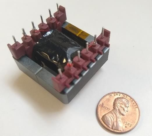
Table 1 PPU Requirements
 Mode Voltage Power
 Chemical 24 V 10 W
 Electrospray 3250 V 1.14 W

 Electrospray PPU Architecture
 Several architectures exist that are capable of providing the high voltage gains necessary for electrospray thruster
 operation. One approach [31] implements a modified flyback converter to feed a Cockcroft-Walton voltage multiplier
 (CWVM). Another approach [32,33] uses a two-phase interleaved boost converter (TPIBC) to feed a series of coupled
 inductors, which drive a CWVM. An architecture proposed by Veeramraju and Kimball [34] contains three main
 stages: a TPIBC, a high-frequency step-up transformer, and a pair of CWVMs. This was the architecture selected for
 the MEPS propulsion system and is shown schematically in Fig. 1.
 This architecture combines several benefits of other topologies to create a PPU well-suited for electrospray
 application. Boost converters have a controllable (rather than fixed) output voltage, which allows for closed-loop
 control of the PPU’s total output voltage. The transformer provides isolation between the low-voltage and high-voltage
Downloaded by 216.171.52.138 on July 28, 2021 | http://arc.aiaa.org | DOI: 10.2514/6.2021-3428

 sides of the PPU, keeping the low-voltage circuitry, probes, and peripherals safer. CWVMs are a common feature of
 electrospray PPUs [30,31,33–36]. These AC-driven circuits provide excellent voltage increase with a relatively low
 component count. In this architecture, the two CWVMs R produce the final high DC voltage at opposite polarities,
 D D D D D D D
 meaning the architecture D D DD D
 Dinherently includes a solution to spacecraft charging. Two thrusters could operate
 simultaneously at .model
 opposite polarities, one emitting positive ions and the other emitting negative ions. It would also be
 ideal_SW SW(Ron=0.0001 Roff=100Meg Vt=.5 Vh=-.4)
 NMOS
 possible to operate a single thruster K L3 L4at
 1 alternating
 NMOS polarities, by using high-voltage switches to periodically change
 .tran 160ms
 which CWVM is connected
 . . to the thruster. However, at the time of this paper, a commercial relay capable of managing
 V2 V3 V1 R1
 these high voltages in a spacecraft environment has not been identified. Thus, the electrospray PPU has been designed
 with the assumption that two thrusters will operate in parallel at opposite polarities. Present designs, simulations, and
 hardware include only a single CWVM for simplicity.

 Two-phase interleaved boost converter Transformer Cockcroft-Walton voltage multiplier

 L1
 C1 C3 C5 C7 C9 C11

 PWM 1 M1
 D1 D2 D3 D4 D5 D6 D7 D8 D9 D10 D11 D12

 C2 C4 C6 C8 C10 C12
 L2
 D13

 V_in
 PWM 2 M2
 Thruster

 Fig. 1 Electrospray PPU Schematic

 Chemical Mode PPU Architecture
 The low required voltage gain (3.25) makes the chemical mode PPU significantly simpler than the electrospray
 PPU. Although many DC-DC topologies exist, a boost converter (shown in Fig. 2) was chosen for this PPU.
 Topologies including a transformer would add unnecessary weight to a small spacecraft, and since boost converters
 were already selected as part of the electrospray PPU architecture, they were a convenient choice for the chemical
 mode PPU as well. Familiarity with the boost converter topology will benefit both PPUs, and parts of simulations or
 hardware can be shared between the two.

 3

L1 D1

 V_in C1 Heater
 PWM M1

 Fig. 2 Chemical Mode PPU Schematic

 Electrospray PPU Details and Simulations
 The following section gives a first-order analysis of the electrospray PPU architecture and presents preliminary
 simulation results. The components of the PPU referenced in the following discussion are shown in Fig. 1. The transfer
 function for a boost converter operating in continuous conduction mode (CCM) is given by Eq. 1:

 = (1)
 1−
Downloaded by 216.171.52.138 on July 28, 2021 | http://arc.aiaa.org | DOI: 10.2514/6.2021-3428

 In this expression, is the converter’s output voltage, is the voltage supplied by the spacecraft bus, and is
 the duty cycle of the boost converter’s switch. By altering the duty cycle of the PWM fed to the switch, the output
 voltage can be managed according to feedback. In this particular electrospray PPU topology, to maintain CCM
 operation, the duty cycle must never fall below 50%.
 Boost converters typically provide a DC output. In this topology, however, the two boost converters take turns
 producing a pulse. Since these alternating pulses enter opposite ends of the transformer primary, the primary
 experiences an AC signal in the form of a modified square wave (MSW). The TPIBC switching frequency was chosen
 to be 100 kHz (mirroring [34]), which therefore must also be the transformer’s operating frequency.
 The transformer has a 1:7 turns ratio. As a consequence, its function is not limited to isolation—it also serves to
 increase voltage by boosting the MSW fed to it. This reduces the TPIBC’s voltage-boosting responsibility, allowing
 for a lower duty cycle and thus reduced switching losses.
 The CWVM takes the boosted AC MSW from the transformer, rectifies it for the final DC output, and further
 boosts the voltage. It is composed of 6 stages, each comprised of two capacitor-diode pairs. The total DC voltage
 produced by a CWVM, , is given by Eq. (2).

 = 2 (2)

 Here, is the number of stages, and is the peak input voltage.
 Given the CWVM and transformer described here, the required duty cycle is about 81%. According to Eq. 1, with
 a 7.4 V input, this gives a TPIBC output of 39 V. When multiplied by the transformer turns ratio and the CWVM
 transfer function from Eq. 2, this gives a total output voltage just above 3.25 kV.
 Preliminary simulations were performed using both LTSpice and PLECS. The results of these full-PPU
 simulations differed from first-order analytical expectations, with a total output voltage reaching well above that for
 which the PPU was designed. These simulations indicated that the PPU output voltage behavior depends significantly
 on the impedance of the output load—in this case, the thruster itself. Figure 3 shows the output voltage behavior for
 two different output impedances. These simulations were both run with 7.4 V at 55% duty cycle, with the same
 1:7 transformer and 6-stage CWVM. According to the transfer functions in Eq. (1) and Eq. (2), a final output voltage
 of 1381 V was expected. However, Fig. 3 shows that for a 1 MΩ output load, the final output voltage reached 1487 V
 during steady state, above the analytical expectation. After increasing the output load to 10 MΩ (the impedance
 representing the MEPS thruster’s steady-state operation), the simulation took about a half second longer to reach a
 steady-state voltage, which had a magnitude reaching well into the 4000 V range. This, of course, is also above the
 analytical estimate of 1381 V. This effect is still being investigated and is a critical part of understanding the PPU’s
 behavior.

 4
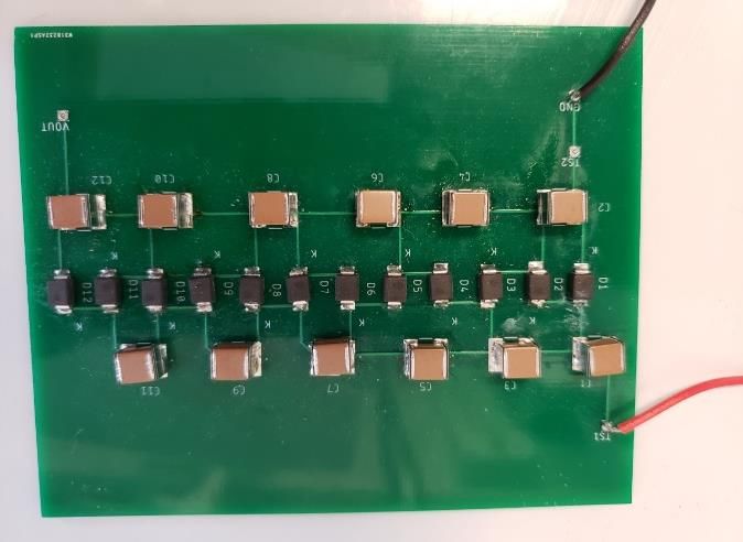
Downloaded by 216.171.52.138 on July 28, 2021 | http://arc.aiaa.org | DOI: 10.2514/6.2021-3428

 Fig. 3 Simulated PPU Output Voltage for Two Loads

 Chemical Mode PPU Details and Simulations
 This section provides a first-order analysis of the chemical mode PPU architecture and presents simulation results,
 and references the chemical mode PPU architecture of Fig 2. The boost converter used in the chemical mode PPU is
 implemented in a much more traditional manner (i.e. with the typical diode and output capacitor). This boost converter
 is also described by the transfer function in Eq. 1. Given an input voltage of 7.4 V, this means that a duty cycle of
 about 70% would be necessary to meet the output voltage requirement. This PPU will run at a 100 kHz switching
 frequency to retain its similarity to the TPIBC boost converters in the electrospray PPU. Figure 4 shows the output
 voltage of this PPU, simulated in PLECS. It reaches steady state in less than a tenth of a second, and has a voltage
 ripple of about 0.06 V.

 Fig. 4 Chemical Mode PPU’s Simulated Output Voltage

 Hardware Construction Status
 In parallel with these simulations, the electrospray PPU electronics are being constructed for testing. The chemical
 mode PPU has not yet reached the hardware prototyping stage, though the TPIBC prototyping will inform its design
 and construction.
 A printed circuit board (PCB) was created for the CWVM, using the IPC-2221 standard for clearance and creepage
 guidance. Typical breadboard prototyping is not an option for the CWVMs since standard breadboard rail spacings
 are unsafe at the high voltages required. Figure 5 shows a CWVM PCB prototype. The taller brown capacitors form
 two rows, with the smaller diodes forming their own row in-between.

 5
Capacitors

 Diodes

 Capacitors

 Fig. 5 CWVM Prototype PCB
 Each capacitor and diode in a CWVM undergoes the same peak voltage stress, , as shown in Eq. (3). Here,
Downloaded by 216.171.52.138 on July 28, 2021 | http://arc.aiaa.org | DOI: 10.2514/6.2021-3428

 refers to the total PPU output voltage.

 = / (3)

 Capacitor and diode selection simplified by this uniform required rating. Additional complications will arise when
 selecting components for the spacecraft environment because arcing can occur due to component outgassing [37].
 This is not a concern for benchtop prototyping purposes but will become relevant as the multimode spacecraft
 propulsion system matures.
 While breadboarding was attempted for the TPIBC stage, unreliable connections and parasitic effects encouraged
 a recent shift to PCB prototyping. The TPIBC inductors were sized according to Eq. (4):
 2
 1 2 3 2
 (1− )4 (1+ ( + − ))
 3 2 6
 ≥ (4)
 8 ( )2

 Here, is the minimum duty cycle (which must be greater than 50% for CCM operation), is the nominal
 thruster impedance, is the operating frequency, is the capacitance of a CWVM capacitor, is the number of
 CWVM stages, and is the transformer turns ratio. This equation, proposed in [34], provides the minimum
 inductance to maintain the TPI operation in CCM.
 The MOSFET switches in this stage were chosen for their small gate charge, which gives them short rise and fall
 times. They also make use of a gate driver, which is commanded by a microcontroller. An STM32 Nucleo board was
 chosen as the microcontroller for its ability to meet the PWM frequency requirement and its ease of implementation.
 This same microcontroller will be used for monitoring the PPU output and providing feedback to the TPI stage. The
 microcontroller will also be responsible for catalyst temperature monitoring when the thruster is operated in chemical
 decomposition mode.
 Figure 6 shows the recently constructed TPIBC. The inductors are oriented perpendicular to each other, to ensure
 minimal interaction of their magnetic fields. The small gate driver is visible in the center, sandwiched between the
 two MOSFETs. During this PCB’s design, care was taken to avoid ground loops and unwanted inductance.

 6
Gate
 MOSFET Inductor
 driver

 Fig. 6 TPIBC Prototype PCB
 The step-up transformer was wrapped in-house around the center post of a small ferrite core. The primary is
Downloaded by 216.171.52.138 on July 28, 2021 | http://arc.aiaa.org | DOI: 10.2514/6.2021-3428

 concentrically sandwiched between the secondary, which had been split into two layers; this enables tighter magnetic
 coupling between the windings. Figure 7 shows the finished transformer with the windings wrapped in an electrically-
 insulating film tape.

 Fig. 7 Step-up Transformer (Penny for Scale)

 Ongoing Work
 The present most pressing goals are to improve the electrospray simulations to better understand characteristics of
 the PPU hardware. Once this PPU’s function is verified in open-loop configuration, feedback will be implemented to
 ensure stable system performance.
 The chemical mode PPU will be constructed according to lessons learned from the TPIBC in the electrospray PPU.
 This PPU will also operate in a closed-loop configuration with the catalyst bed temperature as feedback.
 After this prototyping is complete, both PPUs will be integrated with the existing MEPS thruster for further
 analysis and refinement. Several integration-related challenges are expected, such as problems during electrospray
 PPU startup. The MEPS thruster has also been shown to experience transient arcing events between the emitter and
 extractor, which can be dangerous for the PPU. One solution [37] suggests a resistor in series with the thruster and a
 TVS diode in parallel with that resistor.
 As this technology matures towards actual spaceflight use, PPU size and mass may become a concern. Combining
 the chemical and electrospray PPUs by sharing boost converters is one potential technique for addressing that problem.
 Additionally, it is known that the present parallel-CWVM design is not a perfect solution to spacecraft charging, which
 may still occur at a reduced rate due to manufacturing differences between the two thrusters [29]. A floating ground
 on the high-voltage side of the PPU may passively solve this problem [38]. Practical implementation of this floating
 ground is being explored, and spacecraft charging effects should be mitigated as much as possible before the system
 is flown.

 7
III. Feed System Development

 Background
 The feed system is the series of pressure vessels and flow control elements that deliver the propellant at the
 appropriate flow rate and pressure to the thruster. Depending on the propulsive modes combined in a multimode
 system, the flow rate required for each mode may differ by several orders of magnitude.
 Feed systems for a monopropellant-electrospray multimode system have not previously been developed and
 demonstrated. A multimode system combining cold gas propulsion with a xenon ion thruster, however, was developed
 and flown on the PROCYON spacecraft. The Ion thruster and Cold-gas thruster Unified Propulsion System, or I-
 COUPS, used pressure regulators and flow restrictors to achieve the required pressure for each mode of operation
 [39–41]. A standalone electrospray feed system was developed for ESA’s LISA Pathfinder/ST7 technology
 demonstration mission. The LISA Pathfinder/ST7 mission, launched in 2015, successfully operated a colloid
 electrospray feed system developed by Busek Co. Inc. and JPL. The feed system developed for ST7 pressurized the
 propellant to approximately one atmosphere using mechanical bellows. The flow rate was controlled by a Busek-
 developed microvalve, a piezoelectrically actuated proportional valve [42]. This valve was capable of regulating the
Downloaded by 216.171.52.138 on July 28, 2021 | http://arc.aiaa.org | DOI: 10.2514/6.2021-3428

 flow with 2.5 picoliter/sec flow resolution with a maximum flow rate of 3.5 microliters/min [43]. Ongoing work is
 focused on maturing the LISA Pathfinder propulsion system for the long-duration LISA mission [44].
 The multimode feed system being developed at UIUC builds on the PROCYON, ST7, and LISA feed systems.
 Commonalities between the system presently being developed and the aforementioned systems include gas
 pressurization and a series of pressure reducing orifices and proportional valves to control the propellant flow rate.

 System Requirements and Architecture Selection
 The primary feed system requirement is to deliver propellant flow rates of approximately 850 nL/s for electrospray
 operation and 100 μL/s for chemical mode operation to the thruster. Note that these flow rates correspond to the total
 thruster flow rates and are not the flow rate for each individual microtube. These values, summarized in Table 2, have
 been estimated using information from previous MEPS thruster tests [27,28]. Additional system level requirements
 include minimizing use of consumables (namely pressurant), facilitating rapid testing, primarily using commercial-
 off-the shelf components, and providing a small range of flow rates around the currently anticipated required rates.
 Since the broader propulsion system is still being developed, the required flow rates for each mode may change slightly
 as the design matures. The results of this investigation will inform the next design iteration and, eventually, a flight
 version for an on-orbit demonstration.

 Table 2 Flow Rate Requirements
 Mode Flow Rate
 Chemical 100 μL/s
 Electrospray 850 nL/s

 There are several potential architectures which could deliver the required flow rates to the thruster. An active feed
 system architecture, in which the propellant is pressurized, was selected due to its ability to appropriately deliver
 propellant for both modes. A passive architecture likely would be unable to provide a sufficient flow rate for chemical
 mode operation. Therefore, the system must be actively pressurized either by a gaseous propellant or mechanical
 means. Either pressurization method could allow for constant pressure delivery or variable pressure application.
 Further, one or two flow paths (i.e. one flow path per mode) could be used.
 A constant pressure, gas-pressurized system with separate liquid flow paths for chemical and electric mode
 operation was selected for the initial laboratory (or “benchtop”) feed system architecture. This approach was selected
 for initial testing due to its simplicity and potential ability to meet all system operational requirements while facilitating
 rapid testing using commercially available components. This system is also likely less massive than a mechanically
 pressurized system. Providing constant pressure minimizes pressurant consumption in comparison to a variable
 pressure architecture in which pressurant would need to be vented to transition from a higher pressure to a lower
 pressure. In a flight system, the pressurant gas is a consumable and extraneous consumption should be avoided to
 maximize the lifespan of the propulsion system. The applied pressure shall be equal to that required for chemical mode
 operation, as the flow rate is much higher than the electrospray flow rate. Therefore, significant pressure reduction is
 required for electric mode operation. At this time, neither a single commercially available valve nor a reasonable
 combination of commercial valves has been identified that is capable of allowing sufficient flow for chemical

 8
operation while also providing sufficient flow rate reduction for electric operation. Accordingly, this architecture
 includes a separate flow path for each mode that have different flow control devices.
 The selected configuration is depicted schematically in Fig. 8. Laboratory nitrogen gas will be used to pressurize
 the FAM-110A propellant that is initially loaded inside a propellant tank. The propellant may then be directed to
 follow either the high flow or low flow path (corresponding to chemical mode and electrospray mode, respectively).
 In the high flow path, a proportional valve will be used to regulate the volumetric flow rate to the appropriate level
 prior to the propellant entering the thruster for chemical mode operation. In the low flow path, a series of pressure-
 reducing orifices and proportional valves are required to achieve the required flow rate for electrospray operation.
 Using proportional valves for both modes will allow the flow rate to be varied slightly during testing to meet changes
 in system requirements and account for variations between the built feed system and the idealized model. A nitrogen
 gas purge line is also included for cleaning the system and expelling remnant propellant at the conclusion of testing.
 Check valves are placed throughout the system to constrain the direction of propellant flow.
Downloaded by 216.171.52.138 on July 28, 2021 | http://arc.aiaa.org | DOI: 10.2514/6.2021-3428

 Fig. 8 Benchtop Feed System Schematic

 Modeling
 A model providing a first-order approximation of the feed system performance was created using the electronic-
 hydraulic Ohm’s law analogy and was used to select components for the initial system configuration. This technique
 was also used to compare the ST7 feed system to the proposed feed system for the LISA mission [45]. This method,
 which assumes steady state conditions, models the feed system as a resistive network in which each component’s
 hydraulic impedance, Z, is analogous to electric resistance, R; the volumetric flow rate, Q, is analogous to electric
 current, I; and the pressure drop, ΔP, is analogous to voltage, V (or voltage drop). This is shown symbolically in Eq.
 (5).

 = ⇒ Δ = (5)

 This analogy allows the determination of the pressure drop across each component given the required volumetric
 flow rate and an estimate of each component’s hydraulic impedance. The hydraulic impedance (or resistance) of the
 thruster’s emitter array and manifold as well as the system tubing was readily estimated using the Hagen-Poiseuille
 law. The emitter array may be modelled as a collection of resistors in parallel. These relationships are shown in Eqs.
 (6) and (7) where is the hydraulic resistance of a capillary element, μ is the fluid viscosity, L is the component
 length, and r is the component radius. , represents the resistance of the ith emitter while , is the resistance
 of the entire array.

 9
8
 = 4 (6)

 −1
 1 1 1
 , = ( + + ⋯ ) (7)
 ,1 ,2 ,

 The pressure drop across each component may then be found using Eq. (8), where the subscript i refers to the ith
 element of the system.

 Δ = (8)

 In keeping with the traditional approach of designing CubeSats, commercially available components will be used
 when possible. The flow through commercially available valves and orifices is traditionally described in terms of a
 flow coefficient, . This coefficient relates the volumetric flow rate through the valve or orifice, Q, to the specific
 gravity of the fluid, SG, and the pressure drop across said valve or orifice, ΔP, as shown in Eq. (9).

 = √Δ (9)
Downloaded by 216.171.52.138 on July 28, 2021 | http://arc.aiaa.org | DOI: 10.2514/6.2021-3428

 It is important to note that while the specific gravity of the fluid is considered in the flow coefficient expression,
 the viscosity of the fluid is not. Generally, the liquid used by manufacturers to determine the flow coefficient is water
 or isopropyl alcohol. Therefore, a correction to the flow coefficient may be needed if the liquid of interest has a
 significantly different viscosity than that used in the calibration. While several sophisticated methods for estimating
 the correction due to viscosity exist, they generally require a higher level of knowledge of the particular geometry of
 a given valve than manufacturers provide. A simplistic model, however, was proposed by the Womack Machine
 Supply Co. in a 1989 Design Data Sheet*. This model linearly related the dynamic viscosity of the fluid of interest to
 a viscosity correction factor, f, that may be used to correct the quoted flow coefficient for viscosity according to Eq.
 (10).

 , = (10)

 The validity of this model will be assessed during system testing.
 By substituting the corrected flow coefficient into Eq. (9) for the uncorrected value, the predicted pressure drop
 across a given valve or orifice may be found. Summation of the pressure drops across each component in the feed
 system using the hydraulic impedance (as in Eq. (8)) or the flow coefficient (as in Eq. (9)) allows the total system
 pressure drop to be determined. The total system pressure drop is equivalent to the applied pressure required to achieve
 a given flow rate. With variable position valves (e.g. proportional valves), the flow coefficient may be changed. This
 allows a range of flow rates to be achieved for a given (constant) pressure. This is particularly important for controlling
 the flow of a fluid that has a viscosity that is highly dependent on temperature.

 Predicted System Performance
 Figure 9 shows the relationship between applied pressure (psia) and the resulting flow rate for a given proportional
 valve setting along the high flow path (chemical mode) using water and FAM-110A. This pressure corresponds to that
 measured at the location of the pressure transducer shown in Fig. 8. The estimated flow rate impedance for the thruster
 is included in these predictions and these flow rates were found using the methods described in the previous section.
 Initial system checkouts will be conducted with water. The viscosity of FAM-110A (presently estimated to be
 approximately 0.13 Pa-s at room temperature [19]) is significantly greater than that of water. Correspondingly, the
 flow rate for FAM-110A is lower when compared to water for the same applied pressure. Fig. 9 reveals an applied
 pressure of approximately 70 psi corresponds to the required flow rate for chemical mode operation (100 μL/s) using
 FAM-110A.

 *
 Womack Machine Supply Co., “HOW TO USE FLOW COEFFICIENTS (Cv) FOR HYDRAULIC FLUIDS,” FLUID POWER
 Design Data Sheet, Revised Sheet 17 – Womack Design Data File, 1989.
 URL: https://www.womackmachine.com/media/272815/17-how-to-use-flow-coefficients-cv-for-hydraulic-fluids.pdf [retrieved
 22 Jan 2021].

 10
Downloaded by 216.171.52.138 on July 28, 2021 | http://arc.aiaa.org | DOI: 10.2514/6.2021-3428

 Fig. 9 High Flow Path Flow Rate Predictions
 Figs. 10 and 11 similarly show the predicted flow rates using water and FAM-110A in the low flow path for
 electric mode operation. Here the predicted flow rate impedance for the thruster as well as that from preliminarily
 sized pressure reducing orifices is included. Here, a reduction in flow rate by several orders of magnitude is visible
 between the water and propellant predictions due to the propellant’s viscosity. The proportional valve setting and
 orifices sizes were selected such that the required flow rate of 850 nL/s of FAM-110A is achieved with an applied
 pressure of 70 psi (i.e. the same applied pressure used for chemical mode operation).

 Fig. 10 Low Flow Path Predicted Flow Rate using Fig. 11 Low Flow Path Predicted Flow Rate using
 Water FAM-110A

 Ongoing work and Testing Plans
 Ongoing work includes finishing assembly of the feed system and preparing for initial testing. The primary
 objectives of the testing sequence are to validate the steady-state model (including the valve flow coefficient viscosity
 correction), examine the system’s capability with respect to system requirements, and look for instabilities or temporal
 variations in the flow rate provided. The key relationship to be examined is the flow rate as a function of the applied
 pressure for various proportional valve settings. A pressure transducer will be used to measure the applied pressure
 and mass collection over time will be used to measure the flow rate. Other methods, such as optically tracking seeded
 bubbles may also be used for flow rate measurement (n.b. a commercially available flowmeter with sufficient
 resolution across the range of required flow rates has not been found). Determination of the resolution of flow rates
 that may be achieved via the proportional valves is also of interest.
 Testing will take place in the Electric Propulsion Laboratory at UIUC. The initial tests will be conducted with
 water prior to testing with FAM-110A propellant. This will allow rapid, safe comparison of system performance to
 the predicted performance. Although pressure reducing orifices have been preliminarily sized, the initial tests will not

 11
include pressure reducing orifices in the low flow path to allow for resizing based on system performance. The results
 of the initial testing campaign will inform the feed system’s next design iteration.
 Future work will include identifying ways to minimize system volume and mass as well as identifying components
 that may be used in a flight system. Methods of reducing the required applied pressure will also be investigated and
 the propellant’s viscosity as a function of temperature will need to be determined. Excessive thermal soak back is a
 potential concern during chemical mode operation for a flight system and will be explored following integration of
 the benchtop feed system with the MEPS thruster.

 IV. Conclusion
 This paper details the ongoing PPU and feed system development for a multimode spacecraft propulsion system
 at UIUC in collaboration with Froberg Aerospace, LLC. The selected PPU and feed system architectures have been
 described. The electrospray PPU hardware and its accompanying simulations will continue to be investigated and
 improved to achieve a stable output voltage of 3.25 kV DC. The chemical mode PPU, which must deliver 24 V DC,
 will be assembled in the near future and its performance will be verified. Feed system construction is nearly complete.
 Verification of the system’s ability to deliver volumetric flow rates of approximately 850 nL/s in electrospray mode
 and 100 μL/s for chemical mode operation will follow the completion of construction. The PPUs and the feed system
Downloaded by 216.171.52.138 on July 28, 2021 | http://arc.aiaa.org | DOI: 10.2514/6.2021-3428

 will be integrated with the MEPS thruster following individual verification of both systems.

 Acknowledgments
 The authors thank Christopher Lyne and Dr. Michael Lembeck from UIUC; Kartikeya Veeramraju and Dr.
 Jonathan Kimball from Missouri University of Science and Technology; Thomas Liu, Corey Rhodes, and Luis Pinero
 from NASA Glenn Research Center; and Khary Parker from NASA Goddard Space Flight Center for their time,
 expertise, and insight. This work was completed at the University of Illinois Urbana-Champaign as part of the NASA
 SmallSat Technology Partnerships program, grant number 80NSSC20M0089.

 References

 [1] Rovey, J. L., Lyne, C. T., Mundahl, A. J., Rasmont, N., Glascock, M. S., Wainwright, M. J., and Berg, S. P., “Review of
 Multimode Space Propulsion,” Progress in Aerospace Sciences, Vol. 118, 2020.
 https://doi.org/10.1016/j.paerosci.2020.100627.
 [2] Berg, S. P., and Rovey, J. L., “Assessment of High-Power Electric Multi-Mode Spacecraft,” The 33rd International
 Electric Propulsion Conference, Washington, D.C., Oct. 6-10, 2013.
 [3] Berg, S. P., and Rovey, J., “Assessment of Multi-Mode Spacecraft Micropropulsion Systems,” 50th
 AIAA/ASME/SAE/ASEE Joint Propulsion Conference, Cleveland, OH, July 28-30, 2014. https://doi.org/10.2514/6.2014-
 3758.
 [4] Berg, S. P., and Rovey, J. L., “Assessment of Multimode Spacecraft Micropropulsion Systems,” Journal of Spacecraft
 and Rockets, Vol. 54, No. 3, 2017, pp. 592–601. https://doi.org/10.2514/1.A33649.
 [5] Berg, S. P., and Rovey, J. L., “Design and Development of a Multi-Mode Monopropellant Electrospray Micropropulsion
 System,” 30th Annual AIAA/USU Conference on Small Satellites, Logan, UT, Aug. 6-11, 2016.
 [6] Donius, B. R., and Rovey, J. L., “Ionic Liquid Dual-Mode Spacecraft Propulsion Assessment,” Journal of Spacecraft and
 Rockets, Vol. 48, No. 1, 2011, pp. 110–123. https://doi.org/10.2514/1.49959.
 [7] Fonda-Marsland, E., and Ryan, C., “Preliminary Ionic Liquid Propellant Selection for Dual-Mode Micro-Propulsion
 Systems,” 53rd AIAA/SAE/ASEE Joint Propulsion Conference, Atlanta, GA, July 10-12, 2017.
 https://doi.org/10.2514/6.2017-5019.
 [8] J.F.d. l. Mora, “Efficient Electrospray Propulsion with Widely Variable Specific Impulse: Supplement to AFOSR Grant
 FA9550-06-1-0104,” AFOSR Final Report, FA9550-06-1-0104, 2010.
 [9] Berg, S., and Rovey, J., “Dual-Mode Propellant Properties and Performance Analysis of Energetic Ionic Liquids,” 50th
 AIAA Aerospace Sciences Meeting including the New Horizons Forum and Aerospace Exposition, Nashville, TN, Jan. 9-
 12, 2012. https://doi.org/10.2514/6.2012-975.
 [10] Berg, S. P., and Rovey, J. L., “Assessment of Imidazole-Based Ionic Liquids as Dual-Mode Spacecraft Propellants,”
 Journal of Propulsion and Power, Vol. 29, No. 2, 2013, pp. 339–351. https://doi.org/10.2514/1.B34341.
 [11] Berg, S., and Rovey, J., “Ignition Evaluation of Monopropellant Blends of HAN and Imidazole-Based Ionic Liquid Fuels,”
 50th AIAA Aerospace Sciences Meeting including the New Horizons Forum and Aerospace Exposition, Nashville, TN,
 Jan. 9-12, 2012. https://doi.org/10.2514/6.2012-974.
 [12] Berg, S. P., and Rovey, J. L., “Decomposition of Monopropellant Blends of Hydroxylammonium Nitrate and Imidazole-
 Based Ionic Liquid Fuels,” Journal of Propulsion and Power, Vol. 29, No. 1, 2013, pp. 125–135.
 https://doi.org/10.2514/1.B34584.

 12
[13] Berg, S. P., and Rovey, J., “Decomposition of a Double Salt Ionic Liquid Monopropellant on Heated Metallic Surfaces,”
 52nd AIAA/SAE/ASEE Joint Propulsion Conference, Salt Lake City, UT, July 25-27, 2016. https://doi.org/10.2514/6.2016-
 4578.
 [14] Berg, S. P., and Rovey, J., “Decomposition of a Double Salt Ionic Liquid Monopropellant in a Microtube for Multi-Mode
 Micropropulsion Applications,” 53rd AIAA/SAE/ASEE Joint Propulsion Conference, Atlanta, GA, July 10-12, 2017.
 https://doi.org/10.2514/6.2017-4755.
 [15] Mundahl, A. J., Berg, S. P., Rovey, J., Huang, M., Woelk, K., Wagle, D., and Baker, G., “Characterization of a Novel
 Ionic Liquid Monopropellant for Multi-Mode Propulsion,” 53rd AIAA/SAE/ASEE Joint Propulsion Conference, Atlanta,
 GA, July 10-12, 2017. https://doi.org/10.2514/6.2017-4756.
 [16] Mundahl, A., Berg, S. P., and Rovey, J., “Linear Burn Rates of Monopropellants for Multi-Mode Micropropulsion,” 52nd
 AIAA/SAE/ASEE Joint Propulsion Conference, Salt Lake City, UT, July 25-27, 2016. https://doi.org/10.2514/6.2016-4579.
 [17] Mundahl, A. J., Rovey, J., and Berg, S. P., “Linear Burn Rate of Monopropellant for Multi-Mode Micropropulsion,” 2018
 Joint Propulsion Conference, Cincinnati, OH, July 9-11, 2018. https://doi.org/10.2514/6.2018-4970.
 [18] Rasmont, N., Broemmelsiek, E. J., Mundahl, A., and Rovey, J., “Linear Burn Rate of Ionic Liquid Multimode
 Monopropellant,” AIAA Propulsion and Energy 2019 Forum, Indianapolis, IN, Aug. 19-22, 2019.
 https://doi.org/10.2514/6.2019-4294.
 [19] Berg, S. P., Rovey, J., Prince, B., Miller, S., and Bemish, R, “Electrospray of an Energetic Ionic Liquid Monopropellant
 for Multi-Mode Micropropulsion Applications,” 51st AIAA/SAE/ASEE Joint Propulsion Conference, Orlando, FL, July
Downloaded by 216.171.52.138 on July 28, 2021 | http://arc.aiaa.org | DOI: 10.2514/6.2021-3428

 27-29, 2015. https://doi.org/10.2514/6.2015-4011.
 [20] Wainwright, M. J., Rovey, J.L., Miller, S.W., Prince, B.D., and Berg, S.P., “Electrospray Mass Spectroscopy of a HAN-
 Based Monopropellant,” 2018 Joint Propulsion Conference, Cincinnati, OH, July 9-11, 2018.
 https://doi.org/10.2514/6.2018-4725.
 [21] Wainwright, M. J., Rovey, J., Miller, S. W., Prince, B. D., and Berg, S. P, "Hydroxylammonium Nitrate Species in a
 Monopropellant Electrospray Plume," AIAA Propulsion and Energy 2019 Forum, Indianapolis, IN, Aug. 19-22, 2019.
 [22] Wainwright, M. J., Rovey, J. L., Miller, S. W., Prince, B. D., and Berg, S. P., “Hydroxylammonium Nitrate Species in a
 Monopropellant Electrospray Plume,” Journal of Propulsion and Power, Vol. 35, No. 5, 2019, pp. 922–929.
 https://doi.org/10.2514/1.B37471.
 [23] Mento, C. A., Sung, C.-J., Ibarreta, A. F., and Schneider, S. J., “Catalyzed Ignition of Using Methane/Hydrogen Fuel in a
 Microtube for Microthruster Applications,” Journal of Propulsion and Power, Vol. 25, No. 6, 2009, pp. 1203–1210.
 https://doi.org/10.2514/1.42592.
 [24] Boyarko, G. A., Sung, C.-J., and Schneider, S. J., “Catalyzed Combustion of Hydrogen–Oxygen in Platinum Tubes for
 Micro-Propulsion Applications,” Proceedings of the Combustion Institute, Vol. 30, No. 2, 2005, pp. 2481–2488.
 https://doi.org/10.1016/j.proci.2004.08.203.
 [25] Volchko, S. J., Sung, C.-J., Huang, Y., and Schneider, S. J., “Catalytic Combustion of Rich Methane/Oxygen Mixtures for
 Micropropulsion Applications,” Journal of Propulsion and Power, Vol. 22, No. 3, 2006, pp. 684–693.
 https://doi.org/10.2514/1.19809.
 [26] Wainwright, M. J., Miller, S., Prince, B. D., Berg, S. P., and Rovey, J, “Mass Spectroscopy of a Multi-Mode Propellant in
 Anion and Cation Mode,” 2018 Joint Propulsion Conference, Cincinnati, OH, July 9-11, 2018.
 https://doi.org/10.2514/6.2018-4725.
 [27] Berg, S.P., M.S. Glascock, F.B. Jones, and Rovey, J.L., “Experimental and Modeling Results for the Chemical Mode of
 an Integrated Multimode Thruster,” Joint Army Navy NASA Air Force (JANNAF) 10th Space Propulsion Joint
 Subcommittee Meeting, Tampa, FL., Dec. 9-13, 2019.
 [28] Lyne, C.T., Rovey, J.L., and Berg, S.P., “Monopropellant-Electrospray Multimode Thruster Testing Resultes: Electrospray
 Mode,” AIAA Propulsion and Energy Forum, Virtual Online, Aug. 9-11, 2021.
 [29] Mier-Hicks, F., and Lozano, P. C., “Spacecraft-Charging Characteristics Induced by the Operation of Electrospray
 Thrusters,” Journal of Propulsion and Power, Vol. 33, No. 2, 2017, pp. 456–467. https://doi.org/10.2514/1.B36292.
 [30] Veeramraju, K. J. P., Design and Development of Power Processing Units for Applications in Electrically-Propelled
 Satellite Systems, Master’s Thesis. Missouri University of Science and Technology, Rolla, MO, 2020.
 [31] Hansel, G., Power Conversion and Scaling for Vanishingly Small Satellites with Electric Propulsion. Master’s Thesis.
 Massachusetts Institute of Technology, Cambridge, MA, 2014.
 [32] Baddipadiga, B. P. R., Prabhala, V. A. K., and Ferdowsi, M., “A Family of High-Voltage-Gain DC–DC Converters Based
 on a Generalized Structure,” IEEE Transactions on Power Electronics, Vol. 33, No. 10, 2018, pp. 8399–8411.
 https://doi.org/10.1109/TPEL.2017.2777451.
 [33] Baddipadiga, B. P., Strathman, S., Ferdowsi, M., and Kimball, J. W., “A High-Voltage-Gain DC-DC Converter for
 Powering a Multi-Mode Monopropellant-Electrospray Propulsion System in Satellites,” 2018 IEEE Applied Power
 Electronics Conference and Exposition (APEC), San Antonio, TX, Mar. 4-8, 2018, pp. 1561–1565.
 https://doi.org/10.1109/APEC.2018.8341224.
 [34] Prasad Veeramraju, K. J., and Kimball, J. W., “An Improved Power Processing Unit for Multi-Mode Monopropellant
 Electrospray Thrusters for Satellite Propulsion Systems,” 2019 IEEE Energy Conversion Congress and Exposition
 (ECCE), Baltimore, MD. Sept. 29-Oct. 3, 2019, pp. 1302–1309. https://doi.org/10.1109/ECCE.2019.8913026.

 13
[35] Hruby, V., Gamero-Castano, M., Spence, D., Gasdaska, C., Demmons, N., McCormick, R., Falkos, P., Young, J., and
 Connolly, W., “Colloid Thrusters for the New Millennium, ST7 DRS Mission,” 2004 IEEE Aerospace Conference
 Proceedings, Big Sky, MT, Mar. 6-13, 2004, pp. 202–213. https://doi.org/10.1109/AERO.2004.1367606.
 [36] Howe, D., DESIGN OF AN ELECTROSPRAY THRUSTER POWER PROCESSING AND DIGITAL CONTROL
 INTERFACE UNIT, Master’s Thesis. California Polytechnic State University, San Luis Obispo, CA, 2020.
 [37] Mier-Hicks, F., Characterization of a Magnetically Levitated Testbed for Electrospray Propulsion Systems, Master’s
 Thesis. Massachusetts Institute of Technology, Cambridge, MA, 2014.
 [38] Krejci, D., Mier-Hicks, F., Fucetola, C., and Lozano, P., “High Efficiency Ionic Liquid Electrospray Propulsion for
 Nanosatellites,” 67th International Astronautical Congress, Guadalajara, Mexico, Sept. 26-30, 2016.
 [39] Kawahara, H., Yaginuma, J. A. K., Koizumi, H., Funase, R., and Komurasaki, K., “Ground Experiment for the Small
 Unified Propulsion System: I-COUPS Installed on the Small Space Probe: PROCYON,” Joint Conference of 30th
 International Symposium on Space Technology and Science, 34th International Electric Propulsion Conference and 6th
 Nano-satellite Symposium, Hyogo-Kobe, Japan, July 4-10, 2015.
 [40] Funase, R., Inamori, T., Ikari, S., Ozaki, N., Koizumi, H., Tomiki, A., Kobayashi, Y., and Kawakatsu, Y., “Initial Operation
 Results of a 50kg-Class Deep Space Exploration Micro-Spacecraft PROCYON,” Small Satellite Conference, Logan, UT,
 Aug. 10-13, 2015.
 [41] Koizumi, H., Kawahara, H., Yaginuma, K., Asakawa, J., Nakagawa, Y., Nakamura, Y., Kojima, S., Matsuguma, T.,
 Funase, R., Nakatsuka, J., and Komurasaki, K., “Initial Flight Operations of the Miniature Propulsion System Installed on
Downloaded by 216.171.52.138 on July 28, 2021 | http://arc.aiaa.org | DOI: 10.2514/6.2021-3428

 Small Space Probe: PROCYON,” TRANSACTIONS OF THE JAPAN SOCIETY FOR AERONAUTICAL AND SPACE
 SCIENCES, AEROSPACE TECHNOLOGY JAPAN, Vol. 14, No. 30, 2016. https://doi.org/10.2322/tastj.14.Pb_13.
 [42] Randolph, T., and Ziemer, J., “Microthruster Propulsion for the Space Technology 7 (ST7) Technology Demonstration
 Mission,” 42nd AIAA/ASME/SAE/ASEE Joint Propulsion Conference & Exhibit, Sacramento, CA, July 9-12, 2006.
 https://doi.org/10.2514/6.2006-4320.
 [43] Zwahlen, J., Hruby, V., Campbell, C., Demmons, N., Ehrbar, E., Freeman, C., Martin, R., Roy, T., Spence, D., Randolph,
 T., and Ziemer, J., “Flow Control Micro-Valve for the ST7-DRS Colloid Thruster,” 44th AIAA/ASME/SAE/ASEE Joint
 Propulsion Conference & Exhibit, Hartford, CT, July 21-23, 2008. https://doi.org/10.2514/6.2008-4930.
 [44] Demmons, N. R., Courtney, D., Alvarez, N., and Wood, Z., “Component-Level Development and Testing of a Colloid
 Micro-Thruster (CMT) System for the LISA Mission,” AIAA Propulsion and Energy 2019 Forum, Indianapolis, IN, Aug.
 19-22 2019. https://doi.org/10.2514/6.2019-3815.
 [45] Demmons, N., Alvarez, N., Wood, Z., Strain, M., and Ziemer, J., “Colloid Micro-Thruster (CMT) Component
 Development & Testing Towards Meeting LISA Mission Requirements,” 36th International Electric Propulsion
 Conference, Vienna, Austria, Sept. 15-20, 2019.

 14
You can also read