GUIDE FOR GROUND BASED AUGMENTATION SYSTEM IMPLEMENTATION - May 2013 - ICAO
←
→
Page content transcription
If your browser does not render page correctly, please read the page content below
INTERNATIONAL CIVIL AVIATION ORGANIZATION

GUIDE FOR GROUND BASED AUGMENTATION
       SYSTEM IMPLEMENTATION

                                                 May 2013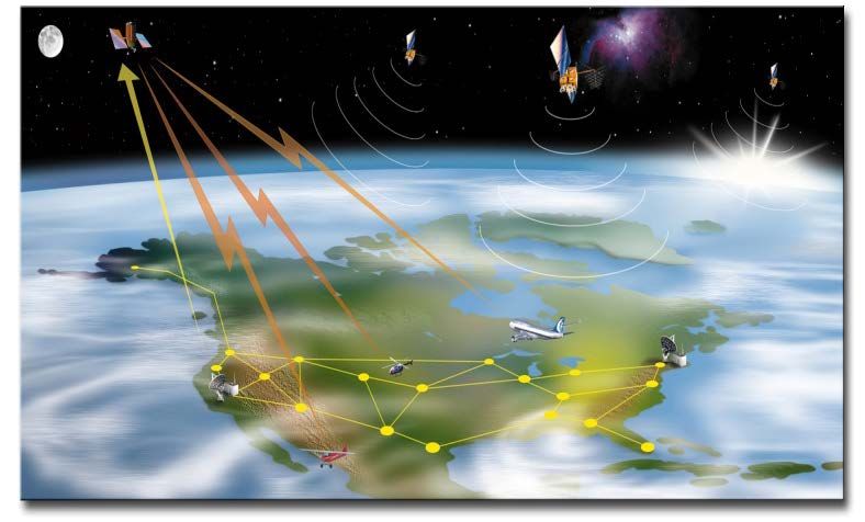
-2-

                                              Foreword

        The Ground Based Augmentation System (GBAS) is being developed and implemented in
several countries and a large amount of information is being generated. This guide intends to be a basis
for countries interested in implementation of GBAS.

      Considering the continuous development of GBAS, this manual should be considered a living
document to be constantly updated.

        Comments are well appreciated and should be addressed to icaosam@icao.int.
-3-
TABLE OF CONTENTS
1 Introduction ...............................................................................................................................4
2 Global Navigation Satellite System (GNSS) .................................................................................6
2.1 Core Satellite Constellations .................................................................................................6
2.1.1 Global Positioning System (GPS) ..................................................................................6
2.1.2 Globalnaya Navigatsionnay Sputnikovaya Sistema (GLONASS) .....................................7
2.2 GNSS Receivers ..................................................................................................................8
2.3 Augmentation Systems .........................................................................................................8
2.3.1 Aircraft-Based Augmentation System (ABAS) ...............................................................9
2.3.2 Ground-Based Regional Augmentation System (GRAS) ...............................................10
2.3.3 Satellite-Based Augmentation System (SBAS) .............................................................10
3 Ground Based Augmentation System (GBAS) ............................................................................11
3.1 General description ............................................................................................................11
3.2 Benefits of GBAS ..............................................................................................................13
3.2.1 Reduction of critical and sensitive areas .......................................................................13
3.2.2 Curved approach ........................................................................................................13
3.2.3 Positioning service......................................................................................................13
3.2.4 Provision of service in several runways at the same airport ............................................14
3.2.5 Provision of several approach glide angles and displaced threshold ................................14
3.2.6 Guided missed approach .............................................................................................14
3.2.7 Adjacent airports use ..................................................................................................14
3.3 GBAS basic technical information ......................................................................................14
3.3.1 Data content ...............................................................................................................16
3.3.1.1 Type 1 message...................................................................................................16
3.3.1.2 Type 2 message...................................................................................................17
3.3.1.3 Type 4 message...................................................................................................17
3.3.2 Channel number .........................................................................................................18
3.3.3 GBAS receiver ...........................................................................................................18
3.3.4 Siting considerations...................................................................................................19
3.3.5 Frequency interference issues ......................................................................................20
3.3.6 Influence of the Ionosphere .........................................................................................20
3.4 Development of GBAS ......................................................................................................22
3.4.1 International GBAS Working Group (IGWG)...............................................................22
3.4.2 GBAS station manufacturers .......................................................................................23
3.4.3 GBAS receiver manufacturers .....................................................................................23
3.4.4 GBAS in aircraft manufacturers...................................................................................23
3.5 Considerations for GBAS implementation ...........................................................................23
3.5.1 Implementation Planning ............................................................................................23
3.5.2 Analysis of ionosphere impact on GBAS......................................................................24
3.5.3 Personnel Training......................................................................................................26
3.5.4 GBAS ground station acquisition and installation .........................................................26
3.5.5 Certification and operational approvals ........................................................................26
4 List of acronyms .......................................................................................................................28
5 List of references in the document .............................................................................................30
6 List of reference documents ......................................................................................................31-4-
Guide for Ground Based Augmentation System Implementation
1 Introduction
All navigation and approach aids (NAVAIDs) must meet the requirements of accuracy,
continuity, availability and integrity specified to each phase of flight.
As the air traffic flow increased, the conventional NAVAIDs were not able to provide the
flexibility in airspace to absorb this growth fitting the needs of the requirements referred so above.
The development, initially by the United States, of a global system providing positioning and
timing services allowed the introduction of an alternative to those conventional NAVAIDs with the
possibility of using new concepts in air navigation capable of satisfying the new needs of the aeronautical
community.
As the development of new concepts and systems occurred, the International Civil Aviation
Organization (ICAO) introduced the Global Navigation Satellite System (GNSS), which allows
navigation in all phases of flight and precision approach and, according to Volume 1 of Annex 10 to the
Convention on International Civil Aviation (from here on referred to as Annex 10, vol.1), is comprised
by:
Global Positioning System (GPS) that provides the Standard Positioning System (SPS);
Global Navigation Satellite System (GLONASS) that provides the Channel of Standard
Accuracy (CSA) navigation signal;
Aircraft-based augmentation system (ABAS);
Ground-based augmentation system (GBAS);
Ground-based regional augmentation system (GRAS); and
Aircraft GNSS receivers.
The list above presents position generation systems (the core constellations), receivers (with these
two groups always present in navigation), and augmentation systems, which will be present when the core
constellations cannot support alone the requirements for the phase of flight.-5- Table 1 – Signal-in-space performance requirements (Annex 10, vol. 1, table 3.7.2.4-1)
-6-

                                2    Global Navigation Satellite System (GNSS)

     As was briefly presented in the introduction, GNSS comprises the core constellations (GPS and
GLONASS), ABAS, GBAS, GRAS and GNSS receivers.

        In order to increase the understanding of GBAS and put it into the GNSS context, it is important
to describe the other components of the system.

                                        2.1    Core Satellite Constellations

          This is, together with the receivers, the basic part of the GNSS. According to Annex 10, two core
satellite constellations have Standards and Recommended Practices (SARPs) incorporated: the GPS from
United States of America and the GLONASS from the Russian Federation. There are two other
constellations under development: GALILEO (European) and COMPASS (Chinese).

       GPS and GLONASS have the capability to provide accurate position and time information
worldwide. The accuracy provided by both systems meets aviation requirements for en-route through
non-precision approach, but not the requirements for precision approach.

        Considering the importance of the core constellations, according to Annex 10, any change in the
SARPs that requires the replacement or update of GNSS equipment require a six-year advance notice.
Similarly, a six-year notice is required of a core or augmentation system provider who plans to terminate
the service provided.

                                    2.1.1     Global Positioning System (GPS)

       GPS is a satellite-based radio navigation system which uses precise range measurements from
GPS satellites to determine position and time anywhere in the world. The system is operated for the
government of the United States by the United States Air Force. In 1994, the United States offered the
GPS standard positioning service (SPS) to support the needs of international civil aviation and the ICAO
Council accepted the offer.

        The design of GPS space segment is comprised of 24 satellites in six orbital planes. The satellites
operate in near-circular 20 200 km (10 900 NM) orbits at an inclination angle of 55 degrees to the
equator; each satellite completes an orbit in approximately 12 hours. The GPS control segment has five
monitor stations and four ground antennas with uplink capabilities. The monitor stations use a GPS
receiver to passively track all satellites in view and accumulate ranging data. The master control station
processes this information to determine satellite clock and orbit states and to update the navigation
message of each satellite. This updated information is transmitted to the satellites via the ground antennas,
which are also used for transmitting and receiving health and control information.

       The navigation data transmitted by the satellites shall include the necessary information to
determine satellite time of transmission, satellite position, satellite health, satellite clock correction,
propagation delay effects, time transfer to UTC and constellation status.

        GPS SPS, which utilizes a coarse acquisition (C/A) code on the L1 frequency (1 575.42 MHz), is
designed to provide an accurate positioning capability for civilian users throughout the world. A precise
positioning service (PPS), which utilizes the Precise Code (P-code) on a second frequency L2 (1 227.6
MHz), provides a more accurate positioning capability, but is encrypted to restrict its use to authorized
agencies.
-7-
On 1 May 2000, the United States discontinued the use of GPS selective availability (SA). The
discontinuation of SA resulted in an immediate improvement of GPS SPS accuracy.
The Interface Control Document (ICD) available in
http://www.navcen.uscg.gov/pubs/gps/icd200/default.htm defines the requirements related to the interface
between the Space Segment (SS) of the GPS and the Navigation User Segment.
GPS uses the geodetic reference datum approved by ICAO WGS-84 (World Geodetic System
1984).
Table 2 – GPS SPS Position Accuracy (Annex 10, vol. 1, item 3.7.3.1.1.1)
2.1.2 Globalnaya Navigatsionnay Sputnikovaya Sistema (GLONASS)
GLONASS provides three-dimensional position and velocity determinations based upon
the measurement of transit time and Doppler shift of radio frequency (RF) signals transmitted by
GLONASS satellites. The system is operated by the Ministry of Defence of the Russian Federation. In
1996, the Russian Federation offered the GLONASS channel of standard accuracy (CSA) to support the
needs of international civil aviation and the ICAO Council accepted the offer.
The nominal GLONASS space segment consists of 24 operational satellites and several
spares. GLONASS satellites orbit at an altitude of 19 100 km (10 310 NM) with an orbital period of 11
hours and 15 minutes. Eight evenly spaced satellites are to be arranged in each of the three orbital planes,
inclined 64.8 degrees and spaced 120 degrees apart.
A navigation message transmitted from each satellite consists of satellite coordinates, velocity
vector components, corrections to GLONASS system time, and satellite health information.
Measurements from a minimum of four satellites are required to establish three-dimensional position and
time. A minimum of three satellite measurements is required to determine two-dimensional position and
time, if altitude is known. The user’s receiver may track these satellites either simultaneously or
sequentially. GLONASS satellites broadcast in two L-band portions of the RF spectrum and have two
binary codes, namely, the C/A code and the P-code, and the data message. GLONASS is based upon a
frequency division multiple access (FDMA) concept. GLONASS satellites transmit carrier signals at
different frequencies. A GLONASS receiver separates the total incoming signal from all visible satellites
by assigning different frequencies to its tracking channels. The use of FDMA permits each GLONASS
satellite to transmit identical P-code and C/A code.
The navigation data message provides information regarding the status of the individual
transmitting satellite along with information on the remainder of the satellite constellation. From a user’s
perspective, the primary elements of information in a GLONASS satellite transmission are the clock
correction parameters and the satellite position (ephemeris). GLONASS clock corrections provide data
detailing the difference between the individual satellite’s time and GLONASS system time, which is
referenced to Coordinated Universal Time (UTC).-8-
Ephemeris information includes the three-dimensional Earth-centred Earth-fixed position,
velocity and acceleration for every half-hour epoch of each satellite. For a measurement time somewhere
between the half-hour epochs, a user interpolates the satellite’s coordinates using position, velocity and
acceleration from the half-hour marks before and after the measurement time.
The GLONASS control segment performs satellite monitoring and control functions, and
determines the navigation data to be modulated on the coded satellite navigation signals. The control
segment includes a master control station and monitoring and upload stations. Measurement data from
each monitoring station is processed at the master control station and used to compute the navigation data
that is uploaded to the satellites via the upload station. Operation of the system requires precise
synchronization of satellite clocks with GLONASS system time. To accomplish the necessary
synchronization, the master control station provides the clock correction parameters.
The Interface Control Document (ICD) for GLONASS is available at http://www.glonass-
center.ru .
As a geodetic system, GLONASS uses PZ-90 (Parameters of Earth 1990 coordinate system), and
the SARPs for GNSS in Annex 10 include a conversion matrix from PZ-90 to WGS-84.
Table 3 – GLONASS CSA Position Accuracy (Annex 10, vol. 1 item 3.7.3.2.1.1)
2.2 GNSS Receivers
A GNSS receiver consists of an antenna and a processor which computes position, time and,
possibly, other information depending on the application. Measurements from a minimum of four
satellites are required to establish three-dimensional position and time. Accuracy is dependent on the
precision of the measurements from the satellites and the relative positions (geometry) of the satellites
used.
2.3 Augmentation Systems
Even though the core constellations and the receivers can provide accuracy, continuity,
availability and integrity to meet from en-route to non-precision approach (NPA) requirements, for
precision approach and procedures that require a greater degree of accuracy or integrity, it is necessary to
have some source of augmentation for these parameters.
The augmentation systems that are listed in Annex 10 SARPs are ABAS, GRAS, SBAS and
GBAS and will be briefly described below.-9-
Except for ABAS, the philosophy of the other augmentation systems is based on the concept of
differential correction, which uses GNSS receivers installed on the ground in a precisely defined position
to calculate the error for each pseudo-range distance measured from satellites in view of the core
constellations. The calculated error for each satellite is then broadcasted so other receivers can correct the
information coming from the satellites.
2.3.1 Aircraft-Based Augmentation System (ABAS)
In the early 1990s, many aircraft operators were quick to adopt GNSS because of the
availability of relatively inexpensive Global Positioning System (GPS) receivers. Operators used these
early receivers as an aid to visual flight rules (VFR) and instrument flight rules (IFR) navigation. They
quickly saw the benefits of having global area navigation (RNAV) capability, and demanded avionics that
could be used for IFR navigation.
The core satellite constellations were not developed to satisfy the strict requirements of
IFR navigation. For this reason, GNSS avionics used in IFR operations should augment the GNSS signal
to ensure, among other things, its integrity. ABAS augments and/or integrates GNSS information with
information available on-board the aircraft to enhance the performance of the core satellite constellations.
The most common ABAS technique is called receiver autonomous integrity monitoring
(RAIM). RAIM requires redundant satellite range measurements to detect faulty signals and alert the
pilot. The requirement for redundant signals means that navigation guidance with integrity provided by
RAIM may not be available 100 per cent of the time. RAIM availability depends on the type of operation;
it is lower for non-precision approach than for terminal, and lower for terminal than for en-route. It is for
this reason that GPS/RAIM approvals usually have operational restrictions. Another ABAS technique
involves integration of GNSS with other airborne sensors such as inertial navigation systems.
Many States have taken advantage of GPS/ABAS to improve service without incurring
any expenditure on infrastructure. The use of GPS/ABAS is a worthwhile first stage in a phased transition
to GNSS guidance for all phases of flight.
Some States have also approved the use of GPS as the only navigation service in oceanic and
remote areas. In this case avionics should not only have the ability to detect a faulty satellite (through
RAIM), but it should also exclude that satellite and continue to provide guidance. This feature is called
fault detection and exclusion (FDE). Under such approval, aircraft carry dual systems and operators
perform pre-flight predictions to ensure that there will be enough satellites in view to support the planned
flight. This provides operators with a cost-effective alternative to inertial navigation systems in oceanic
and remote airspace.
Some aircraft with existing inertial navigation systems have used another ABAS technique which
involves the integration of GNSS with the inertial data. The combination of GNSS fault detection (FD),
or FDE, along with the short-term accuracy of modern inertial navigation systems, provides enhanced
availability of GNSS integrity for all phases of flight.
RAIM algorithms require a minimum of five visible satellites in order to perform fault detection
and detect the presence of an unacceptably large position error for a given mode of flight. FDE uses a
minimum of six satellites not only to detect a faulty satellite but also to exclude it from the navigation
solution so that the navigation function can continue without interruption.-10-
A barometric altimeter may be used as an additional measurement so that the number of ranging
sources required for RAIM and FDE can be reduced by one. Baro aiding can also help to increase
availability when there are enough visible satellites, but their geometry is not adequate to perform
integrity function. Basic GNSS receivers require the use of baro aiding for non-precision approach
operations.
2.3.2 Ground-Based Regional Augmentation System (GRAS)
GRAS was a system conceptually developed but was never set to operation considering its
complexity and the advances in other augmentation systems.
The concept was based on ground reference stations installed all over a large area in precisely
defined positions that transmitted the signal received to a master station capable of processing all
information and generating error correction for each pseudo-range information received from the
satellites.
The master station, then, would send the corrections to VHF stations located all over the area of
interest that broadcasted the corrections according to the satellites in view in the coverage area of each
VHF station.
SBAS Geo Satellite
Galileo Satellite
GPS
Satellite GLONASS Satellite
SBAS Geo
(Ranging Signal Only)
GRAS Master
Reference Station
Stations
VDB
Terrestrial
Communication Links
Figure 1 – GRAS architecture
2.3.3 Satellite-Based Augmentation System (SBAS)
An SBAS augments core satellite constellations by providing ranging, integrity and correction
information via geostationary satellites. The system comprises:
a) a network of ground reference stations that monitor satellite signals;
b) master stations that collect and process reference station data and generate SBAS messages;
c) uplink stations that send the messages to geostationary satellites; and
d) transponders on these satellites that broadcast the SBAS messages.-11-
By providing differential corrections, extra ranging signals via geostationary satellites and
integrity information for each navigation satellite, SBAS delivers much higher availability of service than
the core satellite constellations with ABAS alone. In certain configurations, SBAS can support approach
procedures with vertical guidance (APV). An SBAS approach does not require any SBAS infrastructure
at an airport.
SBAS can support all en-route and terminal RNAV operations. Significantly, SBAS offers the
promise of affordable RNAV capability for a wide cross section of users. This will allow States to
reorganize airspace for maximum efficiency and capacity, allowing aircraft to follow the most efficient
flight path between airports.
There is one operational SBAS that is the Wide Area Augmentation System (from USA) and
several being developed: the European Geostationary Navigation Overlay Service (EGNOS), the Indian
GPS and Geostationary Earth Orbit (GEO) Augmented Navigation (GAGAN) System, the Japanese
Multi-functional Transport Satellite (MTSAT) Satellite-based Augmentation System (MSAS) and the
Russian System for Differential Corrections and Monitoring (SDCM).
Geostationary satellite footprints define the coverage area of an SBAS. Within this coverage area,
States may establish service areas where SBAS supports approved operations.
SBAS may suffer impact of ionosphere behavior with decreasing of positioning accuracy or even
signal interruption. Ionosphere effects are discussed in section 3.3.6 of this guide.
Figure 2 – SBAS architecture
(source http://www.faa.gov)
3 Ground Based Augmentation System (GBAS)
3.1 General description
The current core constellation is unable to provide accuracy, availability, continuity and integrity
to achieve precision approach. GBAS uses the concept of differential corrections to augment satellites
signal in order to meet these requirements.
GBAS provides augmentation to the core constellations to enable precision approach up to
Category III.
In Annex 10, volume 1, to date, there are SARPs for GBAS operating over single frequency and
single constellation to CAT I operations.-12-
SARPs for CAT II/III are already developed by the ICAO Navigation System Panel (NSP) but
not yet included in Annex 10, waiting for developments in the industry.
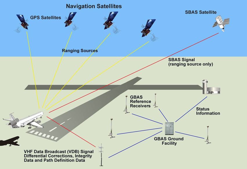
GBAS works based on three segments: satellites constellation, ground station and aircraft
receiver, as shown in Figure 3.
Figure 3 – GBAS architecture
(source http://www.faa.gov)
GBAS ground station is formed by reference receivers with their antennas installed in precisely
surveyed points. The information generated in the receiver is sent to a processor that computes the
corrections for each navigation satellite in view and broadcasts these differential corrections, besides
integrity parameters and precision approach pathpoints data, via a Very High Frequency (VHF) Data
Broacast (VDB).
The information broadcast is received by aircraft in VHF coverage that also receive information
from the navigation satellites. Then, it uses the differential corrections on the information received
directly from the navigation satellites to calculate the precise position.
The precise position is used, along with pathpoints data, to supply deviation signals to drive
appropriate aircraft systems supporting precision approach operations.
The GBAS approach indication to the pilot is similar to the course and glide path indications of
ILS.-13-
3.2 Benefits of GBAS
Comparing to other precision approach systems, GBAS presents lots of benefits:
Reduction of critical and sensitive areas;
Curved approach;
Positioning service;
Provision of service in several runways in the same airport;
Provision of several approach glide angles and displaced threshold;
Guided missed approach; and
Adjacent airports use.
3.2.1 Reduction of critical and sensitive areas
Localizer and glide slope have defined radiation patterns which are essential to the composition
of navigation signals and thus to the precision of the signal received by the aircraft. Any disturbance in
the pattern will cause deviations in the signal.
In order to guarantee that the ILS signal will not be disturbed during instrument approaches
critical and sensitive areas were created and are described in Annex 10, Volume 1.
The creation of critical and sensitive areas, however, produces an operational impact with
restrictions during aircraft approach.
Considering that GBAS does not use antenna patterns to compose the navigation signal, the site
constraints are more related to signal blockage and multipath effects, considerably reducing the
operational impact of critical and sensitive areas and increasing airport operational capabilities comparing
to other precision approach system.
3.2.2 Curved approach
GBAS permits the use of guided curved approach both with lateral and vertical guidance.
This is an important feature if it is necessary to create procedures to avoid aircraft flying over
specific areas close to airports for reasons of noise over urban areas or even to avoid obstacles.
This capability has been proven in test flights in several airports, but there are no SARPs in
Annex 10 on an autopilot capable of executing the automatic procedure, which shall be a requirement,
considering the complexity of this kind of procedure.
The Federal Aviation Administration (FAA) calls this capability TAP (Terminal Approach Path).
3.2.3 Positioning service
The GBAS positioning service provides horizontal position information to support RNAV
operations within the service area.
This feature allows the increase of precision of positioning information and reduction of
separation between aircraft in terminal area.-14-
3.2.4 Provision of service in several runways at the same airport
According to GBAS SARPs, the system may be configured to broadcast a maximum of 48
approaches with different configurations, which may serve different runways with different approach
parameters (see Table 7).
3.2.5 Provision of several approach glide angles and displaced threshold
The 48 different approaches that a single GBAS may broadcast can be configured to different
parameters (see Table 7). In each Final Approach Segment (FAS) data block transmitted, parameters like
glide angle and origin of the glide path can be set differently. Broadcasting different glide angles to the
same runway allows setting approaches that best fit each kind of aircraft operating at the airport.
If there is a need to displace the threshold, GBAS can be quickly configured to support the new
threshold, differently from ILS that should be physically moved to comply with the new position.
3.2.6 Guided missed approach
This is a feature that is not defined in the SARPs but that can be provided by GBAS, increasing
the safety of missed approaches.
3.2.7 Adjacent airports use
The structure of FAS data block allows the same GBAS station to serve different airports (see
Table 7). It has to be within the coverage of the VDB transmitted signal.
3.3 GBAS basic technical information
According to Annex 10, vol. 1, GBAS is intended to support all types of approach, landing,
departure and surface operations and may support en-route and terminal operations.
The SARPs were developed, to date, to support Category I precision approach, approach with
vertical guidance and GBAS positioning service.
The GBAS ground station performs the following functions:
Provide locally relevant pseudo-range corrections;
Provide GBAS-related data;
Provide final approach segment data when supporting precision approach;
Provide ranging source availability data; and
Provide integrity monitoring for GNSS ranging sources.
The coverage shall be capable of supporting the level of service required in specified areas,
covering, at least, according to Figure 4 – Minimum GBAS coverage (Annex 10, vol. 1, fig. D-4).-15-
Figure 4 – Minimum GBAS coverage (Annex 10, vol. 1, fig. D-4)
VDB Frequencies - Data broadcast radio frequencies used in GBAS are selected from the radio
frequencies in the band of 108 to 117.975. The lowest assignable frequency is 108.025 MHz and the
highest assignable frequency is 117.950 MHz. The separation between assignable frequencies (channel
spacing) is 25 kHz.
Access technique - A time division multiple access (TDMA) technique is used with a fixed
frame structure. The data broadcast is assigned one to eight slots.
Modulation - GBAS data is transmitted as 3-bit symbols, modulating the data broadcast carrier
by D8PSK, at a rate of 10 500 symbols per second.
Polarization - GBAS can provide a VHF data broadcast with either horizontal (GBAS/H) or
elliptical (GBAS/E) polarization.
Navigation information - The navigation data transmitted by GBAS includes the following
information:
a) pseudo-range corrections, reference time and integrity data;
b) GBAS-related data;
c) final approach segment data when supporting precision approach; and
d) predicted ranging source availability data.-16-
3.3.1 Data content
The message types that can be transmitted by GBAS are as in Table 4.
Table 4 – GBAS VHF data broadcast messages (Annex 10, vol. 1, Table B-63)
3.3.1.1 Type 1 message
The Type 1 message provides differential correction for individual GNSS ranging sources. The
message contains three sections:
a) message information (time of validity, additional message flag, number of measurements and the
measurement type);
b) low-frequency information (ephemeris decorrelation parameter, satellite ephemeris, Cyclic
Redundancy Check and satellite availability information); and
c) satellite data measurement block.
Table 5 – Type 1 pseudo-range corrections message (Annex 10, vol. 1, table B-70)-17-
3.3.1.2 Type 2 message
The Type 2 message identifies the location of the GBAS reference point at which the corrections
provided by the GBAS apply and gives other GBAS-related data according to Table 6.
Table 6 – Type 2 GBAS-related data message (Annex 10, vol. 1, Table B-71)
3.3.1.3 Type 4 message
The Type 4 message contains one or more sets of Final Approach Segment (FAS) data, each
defining a single precision approach. Each Type 4 message data set includes:
Data set length;
FAS data block – the set of parameters to identify a single precision approach or APV and define
its associate approach path;
FASVAL approach status; and
FASLAL approach status.-18-
Table 7 – Final Approach Segment (FAS) Data block (Annex 10, v. 1, Table B-66)
3.3.2 Channel number
Each GBAS approach transmitted from the ground subsystem is associated with a channel
number in the range of 20 001 to 39 999. If provided, the GBAS positioning service is associated with a
separate channel number in the range of 20 001 to 39 999. The channel number is given by:
Channel number = 20 000 + 40(F – 108.0) + 411(S)
where
F = the data broadcast frequency (MHz)
S = RPDS or RSDS
RPDS = reference path data selector for the FAS data block
RSDS = reference station data selector for the GBAS ground subsystem.
3.3.3 GBAS receiver
The term “GBAS receiver” designates the GNSS avionics that at least meet the requirements for a
GBAS receiver as outlined in Annex 10, vol. 1 and the specifications of RTCA/DO-253A, as amended by
the relevant United States FAA TSO (or equivalent).
Aircraft must have the capability to receive navigation satellites signal and the VDB information,
with respective antennas, and a way to select the approach and an indication of course and glide path.-19-
Like ILS and microwave landing system (MLS), GBAS will provide lateral and vertical guidance
relative to the defined final approach course and glide path. The GBAS receiver will employ a
channelling scheme that selects the VDB frequency. Approach procedure data are uplinked via the VDB.
Each separate procedure requires a different channel assignment.
GBAS avionics standards have been developed to mimic the ILS, in terms of aircraft system
integration, in order to minimize the impact of installing GBAS on the existing avionics. For example,
display scaling and deviation outputs will be equivalent to the ILS. All avionics will provide final
approach course and glide path guidance to all configurations of ground stations.
The GBAS positioning service will provide position, velocity and time data that can be used as an
input to an on-board navigator.
In line with ICAO SARPs and the strategy for the introduction and application of non-visual aids
to approach and landing, which permit a mix of systems providing precision approach service, industry
has developed the multi-mode receiver. This receiver may support precision approach operations based on
ILS, MLS and GNSS (GBAS and SBAS).
For GBAS, integrity monitoring is accomplished by the avionics continually comparing
Horizontal/Lateral and Vertical Protection Levels (HPL/LPL and VPL), derived from the augmentation
signal and satellite pseudorange measurements, against the alert limit for the current phase of flight.
When either the vertical or the horizontal limit is exceeded, an alert is given to the pilot. For a precision
approach, the aircraft GBAS receiver only uses satellites for which corrections are available.
3.3.4 Siting considerations
The installation of a GBAS ground subsystem involves special considerations in choosing
prospective sites for the reference receiver antennas and the VDB antenna(s). In planning antenna siting,
Annex 14 obstacle limitation requirements must be met.
The site should be selected in an area free of obstructions, so as to permit the reception of satellite
signals at elevation angles as low as possible. In general, anything masking GNSS satellites at elevation
angles higher than 5 degrees will degrade system availability.
The antennas for the reference receivers should be designed and sited to limit multipath signals
that interfere with the desired signal. Mounting antennas close to a ground plane reduces long-delay
multipath resulting from reflections below the antenna. Mounting height should be sufficient to prevent
the antenna being covered by snow, or being interfered with by maintenance personnel or ground traffic.
The antenna should be sited so that any metal structures, such as air vents, pipes and other antennas are
outside the near-field effects of the antenna.
Besides the magnitude of the multipath error at each reference receiver antenna location, the
degree of correlation must also be considered. Reference receiver antennas should be located in places
that provide independent multipath environments.
The installation of each antenna should include a mounting that will not flex in winds or under ice
loads.
Reference receiver antennas should be located in an area where access is controlled. Traffic may
contribute to error due to multipath or obstruct view of satellites from the antennas.-20-
The VDB antenna should be located so that an unobstructed line-of-sight exists from the antenna
to any point within the coverage volume for each supported FAS. Consideration should also be given to
ensuring the minimum transmitter-to-receiver separation so that the maximum field strength is not
exceeded. In order to provide the required coverage for multiple FASs at a given airport, and in order to
allow flexibility in VBD antenna siting, the actual coverage volume around the transmitter antenna may
need to be considerably larger than that required for a single FAS. The ability to provide this coverage is
dependent on the VDB antenna location with respect to the runway and the height of the VDB antenna.
Generally speaking, increased antenna height may be needed to provide adequate signal strength to users
at low altitudes, but may also result in unacceptable multipath nulls within the desired coverage volume.
A suitable antenna height trade-off must be made based on analysis, to ensure the signal strength
requirements are met within the entire volume. Consideration should also be given to the effect of terrain
features and buildings on the multipath environment.
3.3.5 Frequency interference issues
GBAS works with navigation satellites frequencies and VHF frequencies for transmitting VDB
information. Both frequency bands are susceptible to suffer interference that can even block the signal.
Causes of interference in 108-118MHz band are well known to affect VOR and Localizers.
In navigation satellites band, the signal is very weak (-160dBm) and thus, susceptible to
interference.
Interference was noticed in GBAS within the navigation satellites band at airports in USA and
Germany, caused by GNSS repeaters and GNSS blockers (jammers).
3.3.6 Influence of the Ionosphere
The ionosphere affects signals broadcast by GNSS (core satellite constellations and SBAS
geostationary satellites) in two ways: it delays the propagation of the modulation (i.e., the code carried by
the signal from which pseudorange measurements are made) and, in some regions, it can cause rapid
fluctuations in the power and phase of the received signal. The first effect is known as “group delay”, the
second as “scintillation”. While the errors in pseudorange measurements caused by group delay are
typically of the order of a few tenths of a meter, they can exceed 100 m on rare occasions.
The behavior of the ionosphere, as far as its observable effects on radio signals are concerned,
varies with time and location. Since the ionization of the upper atmosphere is caused by radiations from
the sun, the density and altitude distribution of the free electrons it contains vary with the 11-year solar
cycle, the season of the year, and time of day. They also vary as a function of geomagnetic latitude.
Finally, they can be severely perturbed by rare geomagnetic (ionospheric) storms caused by powerful
energetic emissions from the sun.
In general ionospheric effects in mid-latitude regions are mild: variations in ionospheric delays
are gradual and scintillation virtually inexistent. This may not be true during severe ionospheric
(geomagnetic) storms, but such storms are very rare, and their effects can be detected, and sometimes
corrected, by augmentation systems. In low-latitude regions, ionospheric effects are more severe: large
variations ionospheric delays and patches causing intense amplitude and phase scintillation are frequent,
particularly during the local evening hours during years near a peak of the solar cycle. Furthermore, steep
ionospheric delay gradients can occur at the edges of deep ionospheric depletions, also known as
ionospheric bubbles. In high-latitude regions, ionospheric effects are more severe than in mid-latitude
regions, but less severe than in low-latitude regions. This is due to the magnitudes of ionospheric delays,-21-
which, while fairly variable, tend to be much smaller than in low-latitude regions. Scintillation can also
occur in high-latitude regions, particularly during periods of increased ionospheric activity. It mostly
occurs in the form of phase scintillation in these regions.
The different GNSS systems use different approaches to correcting for ionospheric delays.
Single-frequency GBAS avionics systems correct for the combined effects of multiple sources of
errors simultaneously, including satellite clock and ephemeris errors, ionospheric delay errors, and
tropospheric delay errors, using the differential corrections broadcast by a GBAS ground station. This
approach to correcting for ionospheric delays is adequate for Category I precision approach operations.
The VHF Data Broadcast function of GBAS broadcasts messages that contain pseudorange
corrections for all satellites in view. When applied, these corrections eliminate, or at least greatly reduce,
the majority of common errors (e.g., ionospheric delay) between the ground and the aircraft. In addition,
the messages also carry parameters characterizing the uncertainties in these corrections. Equations
implemented in the avionics rely on these parameters to calculate protection levels. These protection
levels are then compared to the maximum alert limits for that station and the desired flight operation.
A key limitation on the GBAS corrections is the spatial separation between the GBAS ground
station and the GBAS aircraft user, since the corrections broadcast to the aircraft can only correct
common errors. The main issue here relates to the ionospheric delay, which can vary as a function of
distance. This difference tends to be small over small distances typical of the local area under nominal
ionospheric conditions in the mid-latitudes. (This is not necessarily the case, however, in the equatorial
area where variations can be large even in a local area). Conditions associated with severe mid-latitude
ionospheric storms present a different case. In this case, delay magnitudes can vary quite rapidly over
short distances and thus may not be adequately mitigated even after the corrections from the GBAS
ground station are applied. This presents significant challenges for meeting CAT I requirements and
major design issues for CAT II/III, given the more stringent accuracy and integrity requirements that
apply to these operations. The main challenge is to adequately demonstrate that the system will be able to
meet the integrity and availability requirements during severe ionospheric storms when ionospheric
delays can potentially vary rapidly both in time and space.
250
200
Sun Spot Number
150
100
50
0
1951
1956
1961
1966
1971
1976
1981
1986
1991
1996
2001
Figure 5 – Solar Activity
(source http://www.swpc.noaa.gov/ )-22-
Figure 6 – Ionospheric regions
3.4 Development of GBAS
GBAS was included in Annex 10, Volume 1 by Amendment 76, developed by the Global
Navigation Satellite System Panel (GNSSP) from ICAO, that later became the current Navigation
Systems Panel (NSP).
Several government agencies, industries and universities work on the development of GBAS
ground stations and aircraft receivers and on the operational implementation of the system.
Figure 7 – GBAS stations
(source www.flygls.net)
3.4.1 International GBAS Working Group (IGWG)-23-
Since 2004, the Federal Aviation Administration and Eurocontrol chair the meetings of the
International GBAS Working Group with the attendance of Air Navigation Service Providers,
Certification Authorities, Airport Authorities, Airlines, aeronautical industries, universities and others.
The purpose of the IGWG is to share information regarding GBAS implementation and
development. On February 2011, IGWG was in their 11th meeting.
IGWG information is hosted at https://extranet.eurocontrol.int .
3.4.2 GBAS station manufacturers
Several universities and companies are developing GBAS ground stations. Until mid 2011, only
Honeywell has a certified station (SLS-4000).
Several other companies are working on GBAS projects: IACIT, SELEX, NPPF Spectr, Indra,
Thales, NEC, Park Air, GM Merck and others.
3.4.3 GBAS receiver manufacturers
Avionics companies are developing Multi-mode receivers (MMR), which comprise several
receivers in the same box (VOR, ILS, GNSS). This is interesting for space and weight saving in the
aircraft. Rockwell-Collins has its GLU-925 (GNSS Landing Unit) that is certified for GBAS CAT I
operations. Honeywell is developing an Integrated Navigation Receiver (INR).
Although MMR is a good concept, it is expensive. General aviation lacks a single GBAS
receiver.
3.4.4 GBAS in aircraft manufacturers
The big aircraft manufacturers (Boeing and Airbus) have already implemented GBAS landing
capability in several of their aircrafts.
Airbus offers GBAS CAT I as an optional item for customers in A380, A350 and A320. For
A330 and A340, they are still working on approval for operation.
Boeing offers GBAS CAT I as an optional item in B737-NG and as a regular item in B747-8 and
B787.
3.5 Considerations for GBAS implementation
The implementation of GBAS operations requires a series of activities in order to enable the
accomplishment of an efficient process.
3.5.1 Implementation Planning
The decision of installing a GBAS has effects in several areas of aeronautical community and
must be preceded by a detailed analysis of the scenario.
A study for identification of airports suitable for installation must be conducted followed by a
Cost-benefit analysis (CBA) of the implementation.-24-
The CBA must take in consideration several items like:
Number of aircraft ready to operate GBAS;
Number of aircraft operators committed with the acquisition/modernization of GBAS-
capable aircraft;
Statistical analysis of meteorological conditions;
Evaluation of air traffic growth;
NAVAIDs existing to support nonvisual approaches;
Planning to change the existing NAVAIDs;
Evaluation of the real operational requirements at the airport.
3.5.2 Analysis of ionosphere impact on GBAS
Ionosphere is a challenge for GBAS implementation. Under normal conditions, this layer of the
atmosphere is already causing delays in the signals from GPS satellites, varying according to the region of
the globe.
SAM region, located in the vicinity of the geomagnetic equator, suffers greater impacts because
of the ionosphere particularly with the phenomena of scintillation and plasma bubbles, which can cause
errors in receivers and even cause loss of information from satellites.
Stanford University has developed a threat model to increase the availability of GBAS stations
based on the geometrical arrangement of satellites in space. In addition, they have modeled abnormal
shaped ionosphere gradients as linear wavefronts semi-infinite with constant speed propagation. The
gradient is assumed as a linear variation in the vertical ionosphere delay between a maximum and a
minimum (http://waas.stanford.edu/~wwu/papers/gps/PDF/LeeIONGNSS06.pdf).
Thus, three parameters are essential in this threat model:
Delay difference between two points;
Distance between the points;
Speed of the wavefront.
This threat model, however, applies to date only to the architecture of the station Honeywell SLS-
4000 and was conducted only with data collected in the continental U.S. and is valid for mid-latitude
regions.
A State that purchases a station from other company must ensure the same equipment
certification in accordance with the requirements of accuracy, availability, continuity and integrity
required for the phase of flight that is required to support, even during hostile ionosphere conditions. It
must be clear that manufactures can use a different threat model in their systems and they must be
certificated according to State regulations.
Ensuring that a GBAS system is robust enough to operate at low latitudes may require
simulations or even tests facing the actual events of the ionosphere. The problem of using actual events is
that they are unpredictable and periods of high solar activity, when events become more frequent, occur
every 11 years.-25-
A State wishing to validate Stanford threat model for a specific region should set up a
structure which allows collecting data from GPS satellites to identify and measure the ionosphere
gradients and their speeds. To do this it is necessary to:
1- Install GPS receivers around the area of interest
The receivers must be in large number to allow identification of delays at various points in the
ionosphere.
The receivers must be spaced apart no more than 100 km in order to provide a good definition of
the gradients calculated.
The receivers must be able to receive L1 and L2 frequencies, for a better definition of the
ionosphere delays.
Data acquisition rate of the receivers must be greater than 1Hz for greater definition of the
measures, which will generate a large amount of data.
The mounting location of GPS antennas should preferably be free of obstacles from 5 degrees
elevation.
2- Collect and store data from receivers
Data should be collected periodically from the stations and stored.
Data collection can be accomplished by an external storage device or by a network that performs
the download to a storage server.
3- Identify the occurrence of severe ionosphere events
A software must be used to identify, within the amount of data collected, the occurrence of
significant ionosphere event.
4– Calculate the velocities of the wavefronts and gradients
A software must be used to calculate the velocity of the wavefronts and the gradients referent to
the data with significant ionosphere event.
5- Comparison with the threat model
Finally, the calculated points will be entered into the threat model allowing the evaluation of the
applicability of the model.
It is important to point out that the validation of Stanford threat model is a huge effort, demanding
a high budget to cover expenses with equipment, software and research, and also requires the support of
institutions capable of doing this kind of work.
Besides, the completion of this kind of analysis in an area subject to worse ionosphere behavior is
very useful to areas with better ionosphere.-26-
3.5.3 Personnel training
The transition to GBAS represents a significant change for aviation, so it requires new
approaches to regulation, provision of services and operation of aircraft, and personnel training is the key
for the success of implementation.
Training must include:
Regulators – responsible for updating the regulation to include GBAS operations;
Procedure designers – responsible for the design of new GBAS procedures;
Air traffic services – responsible for airspace traffic control;
Aeronautical information services – responsible for NOTAM and databases;
Aerodrome operators – responsible for the operation of the new GBAS infrastructure;
Pilots;
Airworthiness standards – responsible for approving avionics and installation;
NAVAIDs maintenance personnel – responsible for the maintenance of the GBAS
station.
3.5.4 GBAS ground station acquisition and installation
This phase comprises several activities that include:
Identification of the GBAS manufacturers;
Obtainment of information from the manufacturers;
Definition of technical and logistics requirements for the acquisition;
Obtainment of proposals from the manufacturers;
Selection of the best proposal and contract signature;
Installation and configuration of the station;
Ground and flight tests;
Commissioning.
3.5.5 Certification and operational approvals
An important issue during implementation of GBAS is certification and operational approvals
that are dependant upon the country regulations.
The common steps in certification are: System Design Approval, Facility Approval and
Operational Approval.
System design approval (SDA) refers to the certification of the system as a product. Each state
may have a procedure to do all the SDA or validate the SDA done by another country.
Facility approval refers to the certification of the installation, with the compliance with all the
requirements of the product installed in a specific location and condition.
Operational approval refers to proper operation, and involves existence of regulations, personnel
training and all operational process defined and documented.-27-
Effective implementation
Following the phases of training personnel, updating regulations, installing ground station and
certification, the Aeronautical Authority must render effective the use of the GBAS system.
During the update of regulations, it is important to define the backup infrastructure and alternate
procedures in case of system failure.
Figure 8 – GLS approach chart
(available at http://flygls.net/articles/?c=charts)-28-
4 List of acronyms
The following acronyms are found in the body of this guide:
ABAS - Aircraft Based Augmentation System
APV - Approach with Vertical Guidance
C/A - Coarse Acquisition
CSA - Channel of Standard Accuracy
EGNOS - European Geostationary Navigation Overlay Service
FAA - Federal Aviation Administration
FAS - Final Approach Segment
FDE - Fault Detection and Exclusion
FDMA - Frequency Division Multiple Access
GAGAN - GPS and Geostationary Earth Orbit Augmented Navigation System
GBAS - Ground Based Augmentation System
GEO - Geostationary Earth Orbit
GLONASS - Global Navigation Satellite System
GNSS - Global Navigation Satellite System
GNSSP - Global Navigation Satellite System Panel
GPS - Global Positioning System
GRAS - Ground Based Regional Augmentation System
HPL - Horizontal Protection Level
ICAO - International Civil Aviation Organization
ICD - Interface Control Document
IFR - Instrument Flight Rules
IGWG - International GBAS Working Group
ILS - Instrument Landing System
LAL - Lateral Alert Limit
MLS - Microwave Landing System
MMR - Multi-Mode Receiver
MSAS - MTSAT Satellite Based Augmentation System
MTSAT - Multi-functional Transport Satellite
NAVAID - Navigation Aid
NPA - Non Precision Approach
NSP - Navigation Systems Panel
PPS - Precision Positioning System
RAIM - Receiver Autonomous Integrity Monitoring
RF - Radio Frequency
RNAV - Area Navigation
RPDS - Reference Path Data Selector
RSDS - Reference Station Data Selector
SARPs - Standards and Recommended Practices
SBAS - Satellite Based Augmentation System
SDCM - System for Differential Corrections and Monitoring
SPS - Standard Positioning System
TAP - Terminal Approach Path
TDMA - Time Division Multiple Access
TSO - Technical Standard Order-29- UTC - Universal Time Coordinated VAL - Vertical Alert Limit VDB - VHF Data Broadcast VFR - Visual Flight Rules VHF - Very High Frequency VOR - VHF Omnidirectional Range VPL - Vertical Protection Level WAAS - Wide Area Augmentation System
-30-

                                                   5       List of references in the document

Figure 1 – GRAS architecture........................................................................................................ 10
Figure 2 – SBAS architecture ........................................................................................................ 11
Figure 3 – GBAS architecture........................................................................................................ 12
Figure 4 – Minimum GBAS coverage (Annex 10, vol. 1, fig. D-4) .............................................. 15
Figure 5 – Solar Activity................................................................................................................ 21
Figure 6 – Ionospheric regions....................................................................................................... 22
Figure 7 – GBAS stations .............................................................................................................. 22
Figure 8 – GLS approach chart ...................................................................................................... 27

Table 1 – Signal-in-space performance requirements (Annex 10, vol. 1, table 3.7.2.4-1) .............. 5
Table 2 – GPS SPS Position Accuracy (Annex 10, vol. 1, item 3.7.3.1.1.1) ................................... 7
Table 3 – GLONASS CSA Position Accuracy (Annex 10, vol. 1 item 3.7.3.2.1.1)........................ 8
Table 4 – GBAS VHF data broadcast messages (Annex 10, vol. 1, Table B-63) ......................... 16
Table 5 – Type 1 pseudo-range corrections message (Annex 10, vol. 1, table B-70) ................... 16
Table 6 – Type 2 GBAS-related data message (Annex 10, vol. 1, Table B-71) ............................ 17
Table 7 – Final Approach Segment (FAS) Data block (Annex 10, v. 1, Table B-66) ................... 18
You can also read