APPENDIX I CURRENT AND ADVANCED EMISSION CONTROL STRATEGIES - AND KEY FINDINGS OF CARB/SWRI DEMONSTRATION WORK - DATE OF RELEASE: JUNE 23, 2020 ...
←
→
Page content transcription
If your browser does not render page correctly, please read the page content below
Appendix I
  Current and Advanced Emission Control Strategies
                        and
   Key Findings of CARB/SwRI Demonstration Work

Date of Release: June 23, 2020
Date of Hearing: August 27, 2020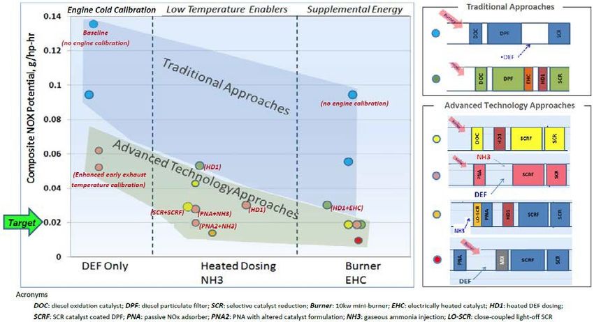
This Page Intentionally Left Blank

Date of Release: June 23, 2020
Date of Hearing: August 27, 2020
LIST OF ACRONYMS AND ABBREVIATIONS USED IN APPENDIX I
Acronym or Abbreviation       Description
A/F                           Air-Fuel
AQMD                          South Coast Air Quality Management District
ASC                           Ammonia Slip Catalyst
AT                            Aftertreatment
BMEP                          Brake Mean Effective Pressure
BTE                           Brake Thermal Efficiency
CAC                           Charge Air Cooler
CARB                          California Air Resources Board
CDA                           Cylinder Deactivation
CHEDE                         Clean High-Efficiency Diesel Engine
CI                            Compression Ignition
CO                            Carbon Monoxide
CSF                           Catalyzed Soot Filter
DEF                           Diesel Exhaust Fluid
DevAged                       Development Aged
DOC                           Diesel Oxidation Catalyst
DPF                           Diesel Particulate Filter
EEVO                          Early Exhaust Valve Opening
EGR                           Exhaust Gas Recirculation
EHC                           Electrically Heated Catalyst
EIVC                          Early Intake Valve Closing
FTP                           Federal Test Procedure
G/BHP-HR                      Grams Per Brake Horsepower-Hour
GHG                           Greenhouse Gas
HC                            Hydrocarbon
HGTR                          Hot Gas Transient Reactor
LEV II                        Low Emission Vehicle II
LEV III                       Low Emission Vehicle III
LEVO                          Late Exhaust Valve Opening
LIVC                          Late Intake Valve Closing
LLC                           Low Load Cycle
LO-SCR, LT-SCR                Light-off SCR
MB                            Mini Burner
MECA                          Manufacturers of Emission Controls Association
N2O                           Nitrous Oxide
NH3                           Ammonia
NO                            Nitric Oxide
NO2                           Nitrogen Dioxide

Date of Release: June 23, 2020
Date of Hearing: August 27, 2020

NOx                           Oxides of Nitrogen
OEM                           Original Equipment Manufacturer
PAG                           Program Advisory Group
PM                            Particulate Matter
PNA                           Passive NOx Adsorber
RMC-SET                       Ramped Modal Cycle – Supplemental Emission Test
RPM                           Revolutions Per Minute
SCR                           Selective Catalytic Reaction
SCRF/ SDPF/ SCROF             SCR Coated on Filter
SI                            Spark-Ignition
SwRI                          Southwest Research Institute
TP                            Tailpipe
TWC                           Three-Way Catalyst
U.S. EPA                      U.S. Environmental Protection Agency
VVA                           Variable Valve Actuation

Date of Release: June 23, 2020
Date of Hearing: August 27, 2020
APPENDIX I

I.   Technological Feasibility of Proposed Standards

This appendix describes currently used key heavy-duty engine emission control
strategies, as well as strategies that can be used to achieve the low oxides of nitrogen
(NOx) emissions standards proposed in this rulemaking action. Section A below
provides an overview of the currently used emission control strategies. Section B below
describes strategies for achieving lower NOx emissions than today’s diesel engine
systems. Section C discusses strategies for reducing NOx further from spark-ignited
(SI) stoichiometric combustion engines. Section D provides a summary of key findings
of the California Air Resources Board’s (CARB) sponsored Southwest Research
Institute (SwRI) Low NOx Demonstration program.

A.   Overview of Existing Strategies

As discussed in Chapter I of this Staff Report, current heavy-duty engines are required
to meet a NOx standard of 0.20 grams per brake horsepower-hour (g/bhp-hr), a
particulate matter (PM) standard of 0.10 g/bhp-hr and a non-methane hydrocarbon
standard of 0.14 g/bhp-hr. To meet these standards, manufacturers are utilizing both
engine and aftertreatment system control strategies for both compression ignition (CI)
and SI stoichiometric combustion engines. Specifically, for CI engines, manufacturers
are using engine controls such as cooled exhaust gas recirculation (EGR), variable
geometry turbochargers, high pressure fuel injection, and other associated electronic
controls, as well as aftertreatment system controls such as diesel oxidation catalyst
(DOC), diesel particulate filter (DPF), urea-based selective catalytic reduction (SCR),
urea injection control, and ammonia slip catalysts (ASC). For SI engines,
manufacturers are using engine controls such as EGR rate control, air-fuel ratio control,
and other associated electronic controls and aftertreatment strategies such as three-
way catalysts (TWC). With better air-fuel ratio controls and increased catalyst volume,
manufacturers have been certifying SI engines to the optional low NOx standards of
0.02 g/bhp-hr NOx, 90 percent below current standards (see Table I-2 of the Staff
Report).

Currently Used Key NOx Emission Control Strategies

1.   Cooled EGR

EGR involves routing some portion of the exhaust gas back into the engine’s
combustion chamber. The exhaust gas dilutes the oxygen fraction of the inlet charge
entering the combustion chamber and reduces the peak combustion temperatures,
thereby reducing the formation of NOx. The use of EGR to reduce NOx emissions can
increase fuel consumption and PM emissions. However, manufacturers have been
mitigating these negative impacts through advances in engine electronic controls,
increased fuel injection pressure, and increased intake manifold boost pressure.
Cooling the EGR exhaust in a heat exchanger before mixing it with the intake air stream
reduces the charge air temperature resulting in lower peak combustion temperatures as
well as allowing a higher density of cooled EGR to be used. The lower peak
combustion temperatures and the higher density of the cooled EGR (which allows a
                                            1
Date of Release: June 23, 2020
Date of Hearing: August 27, 2020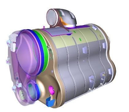
APPENDIX I

higher fraction of EGR to be used) result in improved in-cylinder NOx emission
reductions. EGR controls are also used in SI engines to reduce NOx emissions, inhibit
knock, reduce pumping losses, and improve efficiency.

2.   Turbocharger Control

The turbocharger consists of a turbine and a compressor coupled on a common shaft.
Driven by the waste heat in the exhaust, the turbocharger compresses and increases
the density of the intake air before it enters the combustion chamber. The extra
compressed air forced into the combustion chamber with proportionally more fuel
improves the engine efficiency and provides more power without the need to increase
engine size. However, compressing the intake air also raises its temperature, which
partly offsets the benefits of increasing the intake air pressure. To obtain increased
boost with minimum increase in temperature, a charge air cooler is used to cool the
pressurized air resulting in a high density charge and enabling more fuel to be used to
deliver more power than a naturally aspirated diesel engine. Variable geometry
turbochargers provide additional benefits by maximizing control of the boost pressure
over a wide range of engine operations to provide better transient response, improved
fuel economy, enhanced compression brake capabilities, and improve EGR control to
further reduce emissions.

3.   Exhaust Aftertreatment System

The CI engine aftertreatment system typically consists of a DOC, catalyzed DPF, SCR,
and ASC to clean up the engine exhaust gases (see Figure 1). DOCs use precious
metals such as palladium and platinum to promote oxidation of hydrocarbons (HC) and
carbon monoxide (CO), to either reduce these pollutant emissions from the engine or to
promote exothermic heat used for DPF regeneration and to oxidize nitric oxide (NO) to
nitrogen dioxide (NO2). NO2 is used to promote passive soot DPF regeneration as well
as to promote faster SCR catalytic reactions to reduce NOx.

         Figure 1. Currently Used Diesel Exhaust Aftertreatment System

The DPF is commonly a wall-flow ceramic honeycomb monolith filter coated with
precious metals such as palladium and platinum. The DPF traps soot as the exhaust
passes through the filter walls. The collected soot is then burned or cleaned up in a
process called DPF regeneration which can be done actively or passively, depending on
                                            2
Date of Release: June 23, 2020
Date of Hearing: August 27, 2020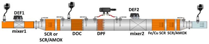
APPENDIX I

the amount of NO2 present in the DPF and the temperature of the exhaust gas. NO2
used in this process is formed in the DOC as well as in the catalyzed DPF by oxidizing
NO to NO2 in the exhaust. Passive regeneration takes place continuously at exhaust
temperatures around 250°C to 350°C in the presence of a sufficient amount of NO2,
which oxidizes the soot to form carbon dioxide (CO2). Active regeneration is initiated by
engine controls based on exhaust system backpressure caused by soot build-up in the
DPF. During active regeneration, heat is typically added to the exhaust stream using a
fuel burner or by injecting fuel over the DOC (HC doser or through post-injection) to
increase the exhaust temperature to above 550°C to burn off soot build up. Ash is also
present in the soot and cannot be burned off. Ash is collected in the DPF and
periodically needs to be cleaned out during set maintenance intervals using a
specialized cleaning process. The minimum ash removal interval allowed by CARB and
U.S. Environmental Protection Agency (U.S. EPA) on-road heavy-duty regulations is
150,000 miles.

To meet the current heavy-duty engine NOx standards, manufacturers are currently
using SCR systems that utilize ammonia as the reductant from a urea-based diesel
exhaust fluid (DEF). In the SCR system, DEF is injected into the hot exhaust stream to
break down the NOx into simple nitrogen and water. For on-road heavy-duty vehicles,
the most commonly used SCR catalysts are copper and iron zeolites and vanadia.
Copper zeolite exhibits an excellent low temperature activity (150°C - 450°C) but is
susceptible to sulfur contamination and requires occasional high temperature
desulfation. Iron zeolite has better high temperature performance (350°C - 600°C) and
is less affected by sulfur contamination reducing the need for high temperature
desulfation but is susceptible to moderate HC poisoning. It also requires better NO2
management in the exhaust gas to achieve needed low temperature NOx control
performance. Vanadia operates best in the temperature window between 300°C to
450°C but has poor durability at higher exhaust temperatures (550°C to 600°C), and
thus cannot be utilized in systems that require active DPF regeneration (which occurs
around 650°C). Similar to iron zeolites, its low temperature performance strongly
depends on NO2 availability in the exhaust. Vanadia-based catalysts are not currently
used for on-road applications in North America due to the possibility of toxic emissions
of vanadia compounds being produced at elevated exhaust gas temperatures that may
occur during active DPF regeneration.

Current SCR systems provide high NOx conversion efficiencies during steady-state and
high-speed operations where exhaust temperatures are high enough for the SCR
system to function effectively. Despite meeting the current standards during certification
test cycles, they have poor NOx conversion efficiency when exhaust gas temperatures
are low, such as during cold start, low-speed, low-load driving and during extended
idling. This is because SCR performance is limited by urea decomposition issues at
exhaust gas temperatures below 180°C. If urea is injected at exhaust gas temperatures
below 180°C, solid deposits of ammonium nitrate can form over the catalyst and
exhaust system, resulting in degradation in SCR conversion efficiency and catalyst
damage. As a result, SCR systems are not operated at low exhaust temperatures that
prevail during low load operations. Unfortunately, these low load conditions dominate
                                            3
Date of Release: June 23, 2020
Date of Hearing: August 27, 2020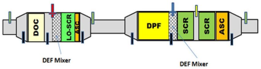
APPENDIX I

actual operation of heavy-duty vehicles in urban stop-and-go operation in communities
and on congested freeways where the reduction of NOx is most needed.

SI natural gas engines use a TWC to control NOX, CO, and HC, without the need of a
DPF to meet PM standards. A TWC uses precious metals such as platinum, palladium,
and rhodium to simultaneously oxidize HC and CO and reduce NOx. Catalytic
conversion efficiency depends highly on the precious metal formulation of the catalyst.
In addition, a necessary condition for high conversion efficiency of the three pollutants is
that the engine operates in a narrow range of air/fuel ratios close to stoichiometric. An
oxygen sensor in the exhaust is used to detect the presence of free oxygen in the
exhaust gas to determine whether the engine is operating on the lean or rich side of
stoichiometry. The sensor then sends a signal to the electronic control unit to adjust
fuel injection rate so that the engine operates in a narrow window around the
stoichiometric set point.

B.   Low NOx Emission Control Strategies

There are two main approaches for reducing emissions further at the tailpipe: engine
controls and aftertreatment system controls. Engine control strategies comprise
software and hardware-based controls designed to achieve more efficient combustion
and reduced engine-out emissions as well as enable improved thermal management of
the exhaust stream for more effective aftertreatment system performance over a wide
range of the vehicle operations. For CI engines, exhaust aftertreatment system control
strategies include improvements to the catalyst formulations, urea injection controls,
exhaust system thermal insulation, supplemental heat addition to the exhaust, and
placement of the aftertreatment system close to the engine. It is not expected that a
single strategy or technology would enable NOx emission reductions necessary to
achieve the levels of the proposed NOx standards. However, adequate NOx emission
reductions to meet the proposed standards can be realized from improved integration of
engine controls with advanced aftertreatment system control strategies.

The following is a brief description of technologies and strategies that could be
implemented to further reduce NOx emissions at the tailpipe. Some of the engine
control strategies and supplemental energy sources designed to add heat to the
exhaust may require additional fuel consumption during cold starts or low temperature
operations. However, the integration and calibration of these technologies is expected
to achieve significant NOx reductions with minimal or no impact on greenhouse gas
(GHG) emissions over the vehicle’s entire duty cycle. In some cases, the selection of
certain engine technologies like cylinder deactivation (CDA) can achieve desired NOx
emission reductions while also reducing GHG emissions (which would help meet
existing Phase 2 GHG requirements). For SI stoichiometric combustion engines,
emission control strategies are less complex but can significantly reduce NOx emissions
with improved TWC formations and advanced air-fuel ratio controls.

                                             4
Date of Release: June 23, 2020
Date of Hearing: August 27, 2020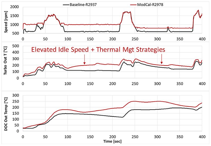
APPENDIX I
1. Engine Calibration Strategies
Engine calibration strategies such as increased idle speed, increased EGR rates, intake
and exhaust throttling, and multiple fuel injection can also be used to increase the
exhaust temperature and accelerate aftertreatment warm-up and reduce engine-out
NOx during cold start conditions. When used in conjunction with advanced
aftertreatment systems, these strategies can be used to achieve NOx emissions levels
below 0.05 g/bhp-hr at the tailpipe. These strategies have been demonstrated by SwRI
in Stages 1, 2, and 3 Low NOx test programs to achieve low levels of tailpipe NOx on
existing diesel regulatory cycles and a newly developed low load cycle (LLC).
In the SwRI Stage 1 Low NOx test program, engine calibration that included increased
idle speed, double post fuel injection, and increased EGR rates together with a stock
aftertreatment system, were able to achieve NOx levels of approximately 36 percent
below baseline on the Federal Test Procedure (FTP) cycle with a corresponding GHG
penalty of about 0.4 percent (Sharp et al., 2017b). In the same program, with advanced
aftertreatment systems that included a passive NOx adsorber (PNA), a fuel burner, SCR
on DPF, a downstream SCR, and ASC, NOx emissions were reduced on the FTP and
the Ramped Modal Cycle - Supplemental Emission Test (RMC-SET) down to 0.016 and
0.02 g/bhp-hr, respectively, using development-aged parts exposed to thermal
degradation of the aftertreatment system at useful life. The thermal and chemically
aged aftertreatment system had FTP and RMC-SET emissions of 0.036 and 0.038
g/bhp-hr, respectively.
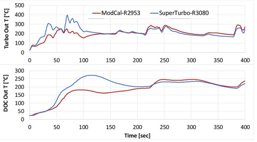
In conjunction with advanced engine hardware and aftertreatment systems, modified
cold calibration strategies are also being used in the SwRI Stage 3 Low NOx program to
demonstrate significantly lower NOx emissions on the regulatory cycles as well as the
LLC. The modified calibration includes increased EGR rates, multiple injections, and
elevated idle speed. The strategy was employed during the first 475 seconds of the
cold FTP after which the calibration was switched to fuel economy calibration mode.
From Figure 2, it is clear that the strategy provides significant increases in exhaust
temperatures enabling rapid aftertreatment warm-up. Using the modified cold
calibration, the time to reach a 150°C DOC outlet temperature was reduced from 233 to
70 seconds and the cumulative engine-out NOx was reduced from 6.3 to 2.0 grams.
However, CO2 emissions on the composite FTP increased by 0.5 percent, and
increases in HC emissions were also observed (Neely et al, 2020a).
5
Date of Release: June 23, 2020
Date of Hearing: August 27, 2020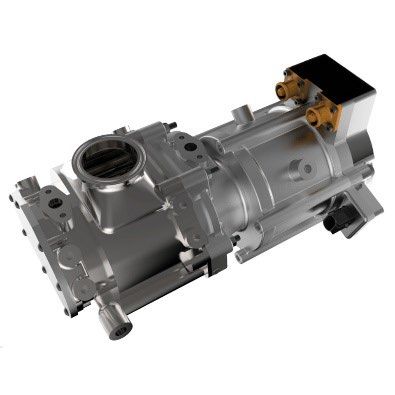
APPENDIX I

        Figure 2. Cold FTP Results with Baseline and Modified Calibration

2.   Bypasses: Turbocharger / EGR cooler/ Charge Air Cooler

The EGR and charge air cooler bypasses allow hot EGR and uncooled charge air to be
routed from the intake manifold into the exhaust chamber during certain operating
conditions. The higher inlet charge temperature improves fuel atomization and air-fuel
mixing during the ignition delay period and during combustion, increasing exhaust
temperatures. A turbocharger bypass allows the exhaust to remain hot at the SCR by
avoiding a heat loss across the turbine walls. The use of these strategies would be
effective under certain engine operating conditions such as during cold start, extended
idle, and light load operations.

These hardware strategies were screened by SwRI in the Stage 3 Low NOx program to
evaluate their potential to increase exhaust temperatures and their impacts on engine-
out NOx and CO2 emissions (Neely et al, 2020a). Among the hardware options
evaluated, SwRI investigated exhaust thermal management using EGR cooler bypass
(bypassing 50 percent of the EGR and completely or 100 percent of the EGR), charge
air cooler (CAC) bypass and turbine bypass. Under steady state tests of 1000
revolutions per minute (rpm) and 2.5 bar brake mean effective pressure (BMEP), a 100
percent EGR cooler bypass provided a temperature increase of 100°C without any
additional fuel penalty but with only a small engine-out NOx impact and soot mass
increase. In addition, HC emissions were also reduced due to increased intake
manifold temperature. Bypassing the CAC in addition to 100 percent of the EGR cooler

                                           6
Date of Release: June 23, 2020
Date of Hearing: August 27, 2020
APPENDIX I
bypass provided another 18°C increase in exhaust temperatures with some soot
increase. For the same test condition, a 50 percent EGR cooler bypass provided
approximately 30°C increase in exhaust temperature with slight soot mass reduction.
The turbine bypass, resulted in approximately 60°C increase in exhaust temperature
with a NOx and exhaust energy decrease, a small fuel consumption increase, and a
slight soot mass reduction.
To conduct the steady state test for the 100 percent EGR cooler bypass, certain
components had to be removed to allow testing due to exceeding temperature limits.
Thus, it was not selected for final demonstration since transient EGR control by the
stock engine control module was not possible without the removed components.
However, the results demonstrate the potential for increasing exhaust gas temperatures
of completely bypassing the EGR cooler.
3. Supplemental Heat Addition
There are several active thermal management approaches for adding heat to the
exhaust:
(i) Direct heat addition to the exhaust by dosing fuel directly into the exhaust or
through post injection, and oxidizing it over the oxidation catalyst or by
combusting the fuel in a fuel burner with the flame entering the exhaust system.
Using a fuel burner or direct in-exhaust fuel dosing for heat addition typically
negatively impacts GHG emissions.
(ii) Use of an “electrically heated catalyst” upstream of the main catalyst to deliver
heat directly to the exhaust gases. The electrical energy needed is generated by
the engine’s alternator and therefore is a parasitic load on the engine, consuming
fuel. However, the GHG penalty can be reduced or eliminated when used in
combination with electric hybrid vehicles where the electrical energy used for
heating exhaust is recovered via braking energy.
(iii) Direct heat addition to the DEF to vaporize it to form ammonia and directly dose
the heated DEF into the exhaust (“Heated DEF Dosing”) at low exhaust
temperatures as low as 130°C. In this strategy the heat can be generated using
an electrical heater or alternatively use heat from the exhaust by taking partial
exhaust flow from the main exhaust upstream of the turbocharger, heating the
urea solution to form ammonia.
The above three strategies were evaluated in the SwRI Stages 1 and 2 Low NOx testing
programs (Sharp et al., 2017b). The fuel burner (or mini burner) system was selected
and used for the final demonstration of the SwRI Stage 1 Low NOx testing program.
4. Passive NOx Adsorber
A PNA is a NOx storage device that is placed upstream of an SCR to store NOx during
cold start and during low temperature operations and then release the NOx at higher
7
Date of Release: June 23, 2020
Date of Hearing: August 27, 2020APPENDIX I
temperatures when the downstream SCR catalyst becomes active. A PNA can
combine the functions of a DOC as well as NOx storage device. A PNA was one of the
aftertreatment technologies used to demonstrate the feasibility of low NOx emissions in
the SwRI Stages 1 and 2 Low NOx test programs. PNAs are effective in reducing cold
start emissions. However, they are sensitive to sulfur contamination which reduces
their adsorption capabilities and requires frequent desulfation at higher exhaust
temperatures to recapture NOx adsorption performance.
5. Advanced SCR Systems
SCR catalyst formulations and designs have been undergoing continuous development
to improve the durability and the overall NOx conversion performance. To improve the
temperature operating window, catalysts with high cell density and thinner, durable,
substrate walls are being developed. The high cell density and increased porosity
provide increased surface area to allow sufficient contact area between the exhaust gas
and the active catalytic materials. The thin substrate walls also reduce the catalyst
thermal mass allowing for more rapid warm-up. Advances in SCR aftertreatment have
improved catalyst efficiency and have widened the operating temperature range
available for NOx control. Other catalyst formulations such as combined-SCR systems
consisting of both iron and copper catalysts benefit from the characteristics of both
copper and iron, allowing improved NOx reduction over a wider range of operating
temperatures (Nishiyama et al., 2015). SCR NOx reduction efficiencies have been
observed to have increased to 90 percent or more at temperatures down to 200°C
(Newman, 2018). Over the years, development of higher efficiency catalysts, improved
DEF mixing, and packaging designs have resulted in overall system downsizing and
cost savings (MECA, 2019).
6. SCR on DPF
SCR on DPF technology (also referred to, by different manufacturers as SCRF, SDPF,
or SCRoF) is an integrated NOx-PM aftertreatment technology where the SCR catalytic
material is coated in the porous walls of the DPF substrate. It combines the
functionalities of both the DPF and the SCR into one aftertreatment component, thereby
reducing system size, weight, thermal mass, complexity, and cost. With the addition of
a compact urea mixer, the system can be close-coupled to the DOC for faster light-off
and improved cold start emissions performance. To maximize NOx conversion, the
system may be coupled with a separate SCR system downstream of the combined
system. Copper and iron-based catalysts are more appropriate for use as SCR
catalysts on the DPF due to their higher thermal stability.
SCR on DPF was one of the technology options evaluated in the SwRI Stages 1 and 2
Low NOx testing programs (Sharp et al., 2017b; Sharp, 2020b). In combination with
other strategies such as engine thermal management strategies (discussed above) and
advanced aftertreatment systems that included a PNA, a fuel burner to provide
supplement heat to the exhaust, and a downstream SCR catalyst, the system achieved
extremely low NOx levels on the regulatory cycles and the LLC.
8
Date of Release: June 23, 2020
Date of Hearing: August 27, 2020APPENDIX I
7. Dual SCR with Dual Dosing
Dual SCR systems consists of two SCR systems arranged in series, each with its own
DEF dosing system. There are several configurations of these systems. The upstream
SCR catalyst, referred to as a “light-off SCR,” could be located close to the engine’s
turbocharger, either upstream of the DOC or just downstream of a close-coupled DOC
and underfloor, but upstream of the DPF. Placing it close to the turbocharger upstream
of the DOC enables the light-off SCR to take advantage of passive thermal
management, using hotter engine exhaust temperature and less thermal mass between
the two components to effectively reduce NOx during cold start and low load operations,
until the downstream SCR temperature reaches its ideal operating state for maximum
NOx control. A zone coated ASC downstream of the light-off SCR is also typically
needed to clean-up any ammonia-slip and prevent ammonia oxidation to form NOx and
nitrous oxide (N2O) over the DOC and the catalyzed DPF. In addition, NOx conversion
over the light-off SCR must also balance the need for NO2 for passive DPF
regeneration.
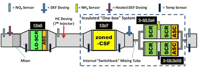
The downstream SCR is typically located in the underbody of the vehicle. The
downstream aftertreatment systems typically include the downstream SCR, the DPF,
and the ASC that can be packaged together in a one-box system or in a traditional
configuration as shown in Figure 3. The zoned-coated catalyzed soot filter (CSF)
combines the functionalities of the DOC and DPF into one component, thereby reducing
system size and providing better thermal management to the downstream SCR.
Promising results have been achieved by technology developers, manufacturers, and
research institutions currently investigating the potential of the dual SCR aftertreatment
architecture to meet very low NOx emission levels. The SwRI Stage 3 Low NOx testing
program is currently demonstrating low NOx emissions using dual SCR catalysts with
dual dosing and other advanced engine calibration and hardware strategies (Zavala et
al., 2020). Results are shown in the summary of SwRI results discussed in section D,
below.
Figure 3. Close-coupled Light-Off SCR Configurations
9
Date of Release: June 23, 2020
Date of Hearing: August 27, 2020APPENDIX I
Testing by Bosch of a 7.8 liter medium-duty engine targeting NOx levels below 0.05
g/bhp-hr demonstrated composite FTP NOx levels of 0.023 g/bhp-hr using engine
calibration methods and a dual SCR system with a close-coupled DOC and light-off
SCR (LT-SCR) as shown in Figure 4 (Freitag, 2019).
Figure 4. Bosch Concept SCR System for Low-NOx Heavy-Duty Diesel Engines
(Denoxtronic 8 SCR System)
Adelman et al. also reported the benefits of placing a light-off SCR upstream of the
DOC on a 2019 model year 12.4-liter “stock” A26 Navistar diesel engine (Figure 5).
Targeting emissions below 0.05 g/bhp-hr tailpipe NOx, this test program demonstrated
composite FTP NOx of 0.04 g/bhp-hr with SCR conversion efficiencies of 96.9 percent
on the cold FTP and 99.7 percent on the hot FTP (Adelman et al., 2020).
Figure 5. “Ultra-Low TP NOx” Aftertreatment Configuration
(Adelman et al., 2020)
The results by both Bosch and Adelman et al. were achieved without using any of the
engine hardware thermal management strategies such as CDA, variable valve
actuation, EGR cooler bypass, etc. These results indicate that NOx emission levels
significantly lower than 0.02 g/bhp-hr are feasible with additional thermal management
strategies such as engine calibration and hardware strategies, or heated DEF dosing.
10
Date of Release: June 23, 2020
Date of Hearing: August 27, 2020APPENDIX I
8. Exhaust System Heat Retention
Reducing the mass of the exhaust system and insulating it from the outlet of the
turbocharger to the inlet of the SCR system would also reduce the amount of heat lost
to the exhaust system’s walls. Double walled manifolds and pipes with a very thin inner
wall and an air gap separating the inner and outer wall may be used to insulate the
exhaust system and reduce the thermal mass, minimizing the amount of heat lost. This
technology is prevalent in gasoline-fueled engine applications and can be applied to
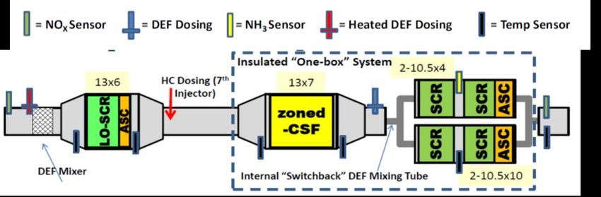
diesel engine applications. As shown in Figure 6, packaging the aftertreatment system
in a one-box system could also be used to reduce overall aftertreatment size and
reduce weight, and keep the aftertreatment system warm over longer periods of time
(i.e., as in a “penguin huddle”).
Figure 6. Downstream Aftertreatment Configuration - One Box System
9. Urea Injection Control
The objective of a urea injection control system is to simultaneously minimize tailpipe
NOx and ammonia emissions by enabling the urea dosing system to inject the precise
amount of urea necessary for NOx conversion. Providing high precision controls is a
requirement for reaching FTP NOx levels of 0.020 g/bhp-hr consistently and over
multiple exhaust conditions. Model-based feed-forward and feedback (Closed-loop)
DEF dosing controls with appropriate exhaust sensors are necessary in applications,
where high NOx conversion efficiency is needed. For a closed-loop SCR control
system, a NOx sensor upstream and downstream of the SCR and mid-bed ammonia
sensors are needed to monitor the amount of ammonia coverage on the SCR catalyst
and adjust the amount of urea injected to reach the coverage design target.
10. Ammonia Slip Catalyst
An ASC is a precious metal-based oxidation catalyst that is used to oxidize excess
unreacted ammonia that may have slipped through the SCR catalyst and would
otherwise be exhausted to the environment. ASCs are designed to have high selectivity
for ammonia, oxidizing ammonia to form nitrogen. However, if the NO to ammonia ratio
coming out of the SCR catalyst is very high, the catalyst may also catalyze undesirable
reactions that produce N2O, a potent GHG, or oxidize the ammonia to produce NOx at
the tailpipe. Thus, careful DEF injection strategies along with improved ASC designs
11
Date of Release: June 23, 2020
Date of Hearing: August 27, 2020APPENDIX I
are being developed to maximize ammonia storage on the SCR while avoiding the
generation of N2O or the oxidation of that ammonia slip into tailpipe NOx. The latest
generations of ASC with reduced precious metal content are showing much better
selectivity for ammonia, while forming lesser undesirable products at the tailpipe.
11. Cylinder Deactivation
Among the many engine hardware technologies (EGR cooler bypass, charge air cooler
bypass, turbine bypass, SuperTurbo, and air gap insulated exhaust manifold) evaluated
by the SwRI Stage 3 Low NOx program, CDA ranked the highest for providing
significant CO2 reductions while also providing significant increases in exhaust
temperatures during the cold FTP test (Neely et al, 2020a).
CDA involves selectively shutting down one or more cylinders by cutting fuel injection as
well as deactivating the intake and exhaust valves of the selected cylinders. The air
trapped inside the deactivated cylinders is compressed and then pushes back the
piston, effectively acting like a “spring.” CDA in diesel engines provides improved fuel
efficiency through reduced pumping losses and friction as well as increased exhaust
gas temperatures for faster warm-up and to keep warm the exhaust aftertreatment
system during idle and sustained low load operation for effective SCR operation.
CDA is currently being investigated and developed by various manufacturers and
technology developers as a technology pathway to meet the proposed low NOx
standards. Singh et al. reported results of CDA tests conducted on a Class 8, 13L,
6-cylinder, Navistar engine on a number of vocational duty cycles including among
others the LLC, the New York Bus Cycle, Orange County Transit Authority Cycle, and
the FTP (Matheaus et al., 2020). Testing on the LLC showed an increase in SCR inlet
temperature by 38°C, which allowed the SCR NOx conversion efficiency to increase
from 74 percent (baseline) to 95 percent with CDA. The tailpipe NOx and CO2 were
reduced by 77 percent and 12 percent, respectively.
Furthermore, another study by SwRI and Eaton demonstrated that a “stay warm” CDA
strategy increased exhaust temperatures of up to 200°C while simultaneously reducing
fuel consumption between 5 and 40 percent, depending on the engine operating speed
and load (Morris et al, 2020).
12. EGR Pump
EGR pumps provide more precise EGR flow rates independent of the engine speed via
a positive displacement pump while allowing the use of high efficiency fixed geometry
wastegate turbochargers (Park et al, 2019) (See Figure 7). Driven by a 48-volt electric
motor, the EGR pump allows a high volume of EGR to be pumped to dilute the intake
charge air mixture with low pumping losses - improving fuel efficiency while also
lowering peak combustion temperatures - reducing engine-out NOx. The EGR pump
enables EGR flow where it was previously difficult or not possible to drive the flow
without losses such as during low speed and transient operations and provides more
accurate EGR flow rate control for better combustion and emissions management.
12
Date of Release: June 23, 2020
Date of Hearing: August 27, 2020APPENDIX I
Figure 7. EGR Pump (source: Eaton)
13. Variable Valve Actuation
Variable valve actuation (VVA) involves changing the timing of closing and opening the
intake or exhaust valves to improve combustion efficiency while also providing improved
thermal management of the exhaust during different engine operating conditions. There
are multiple VVA solutions including early exhaust valve opening (EEVO), late exhaust
valve opening (LEVO), early intake valve closing (EIVC), and late intake valve closing
(LIVC). VVAs are effective strategies for increasing exhaust temperatures at different
engine operating conditions.
For example, EEVO of about 90° earlier than nominal was shown to increase exhaust
temperatures by 30 to 80°C at different engine operating conditions including idle, low
load cruise, and high load cruise conditions (McCarthy et al, 2017). The strategy
resulted in a fuel consumption penalty of approximately 13 percent at high load cruise,
18 to 21 percent at low load cruise, and 22 percent at idle. The same study reported, at
1200 rpm and 2.5 bar BMEP, EIVC and LIVC were shown to increase the turbine-out
exhaust temperature from about 200°C to 255°C° and 244°C, respectively. For the
same engine operating condition, EIVC improved brake-thermal-efficiency (BTE) by
approximately 4 percent while LIVC improved BTE by approximately 3 percent.
Furthermore, another study demonstrated how increased idle speeds and exhaust valve
opening actuation, individually or combined, can be used to significantly increase the
‘‘warm-up’’ rate of an aftertreatment system without emitting higher engine-out NOx or
PM, compared to a high idle thermal calibration strategy (Vos et al., 2019). The study
demonstrated that increased idle speeds together with EEVO increased the engine-out
exhaust gas temperature by 50°C relative to conventional idle operation and LEVO
increased the engine-out exhaust gas temperature by 91°C relative to conventional idle
operation.
14. SuperTurbo
A SuperTurbo is a device that is capable of supercharging, turbocharging, and
turbocompounding. The turbine shaft is linked to the engine’s crankshaft through a
13
Date of Release: June 23, 2020
Date of Hearing: August 27, 2020APPENDIX I
mechanical transmission to enable power transfer between the turbine and the engine.
During transient operation, it acts like a supercharger drawing power direct from the
engine for improved transient response. When the engine operates at high power, it
can act as a turbocharger by taking advantage of the exhaust energy to compress
intake air and thereby improve overall engine performance and efficiency. And finally,
for turbocompounding, it can utilize the excess exhaust energy above that needed to
drive the compressor and providing surplus power to the engine crankshaft, thus
improving fuel efficiency. SwRI was able to demonstrate through limited testing that this
technology can provide significant thermal management improvements during the cold
start FTP. It was also shown that this device can achieve reduced GHG emissions
under a broad range of engine operations (Neely et al, 2020a).
15. Ducted Fuel Injection
Ducted fuel injection is a relatively new fuel spray method that mimics the Bunsen
burner with the potential to reduce PM emissions and improve thermal efficiency of
heavy-duty diesel engines (Nilsen et al, 2018). It involves injecting fuel along the axis of
one or more small cylindrical ducts within the combustion chamber, to enhance the
mixture in the autoignition zone relative to a conventional free-spray configuration
(i.e., a fuel spray that is not surrounded by a duct). The technology has the potential to
reduce PM and NOx simultaneously, breaking the NOx / PM trade-off issue with CI
engines.
16. Achates Engine
The Achates engine is an opposed piston engine currently under development by
Achates Power. The opposed piston engine is expected to significantly reduce tailpipe
NOx emissions while improving fuel economy and will reportedly cost less compared to
a four-stroke CI or SI engine of similar power (Achates, 2020a; Achates, 2020b).
C. Strategies for SI Stoichiometric Combustion Engines
As mentioned above, TWCs use precious metals such as platinum, palladium, and
rhodium to simultaneously oxidize CO and HC, and reduce NOx emissions. Because of
their application in gasoline light-duty vehicles to meet the low emission vehicle (LEV II
and LEV III) standards, TWCs have continued to improve in terms of their performance
and durability since they were first introduced in 1975. Specifically, improvements have
been made relative to catalyst formulation, substrate design, oxygen storage material,
and exhaust thermal management. However, their application in SI heavy-duty engines
is not as optimized as it is in light-duty vehicles, particularly when controlling emissions
during cold start and other certain operating conditions. Thus, lessons learned from
gasoline light-duty applications can also be applied to SI heavy-duty engines to improve
performance. Improvements may include:
i. Substrate design: Higher cell density and thinner wall design can provide
increased geometric surface area per unit TWC volume for effective catalyst
14
Date of Release: June 23, 2020
Date of Hearing: August 27, 2020APPENDIX I
distribution, small flow channels for fast heat transfer, and reduced substrate
thermal mass for faster heat up during cold starts.
ii. High oxygen storage material: High oxygen storage capacity is critical for
maintaining high catalytic conversion. The latest generation of ceria zirconia
added to the washcoat of TWCs provide higher thermally stable oxygen storage
capacity and allows a broader window of catalytic operation, improves catalyst
light-off, and enables significant reductions of NOx emissions (Damma et al,
2018).
iii. Close-coupled catalyst: A close-coupled catalyst minimizes exhaust system heat
losses and accelerates catalyst light-off, without negatively impacting fuel
economy. Close-coupled catalysts use a palladium-only or a palladium and
rhodium formulation for higher HC removal efficiency and faster catalyst light-off.
iii. Passive heat retention: Insulating the exhaust manifold, exhaust pipeline, and
TWC increases the efficiency of transferring heat generated from the engine to
the catalyst with minimum heat loss, so that the transferred heat accelerates
catalyst light-off at cold start and maintains high catalytic conversion efficiency.
v. Advanced air/fuel (A/F) ratio controls: Because a TWC operates within a very
narrow window of A/F ratio, maintaining accurate A/F ratio in cylinders is critical
to achieving maximum catalytic conversion efficiency. Maintaining accurate A/F
ratio control allows for better fuel economy, lower NOx emissions, and better
engine performance. A zirconia-based wideband oxygen sensor widely used in
gasoline passenger cars could be used for SI heavy-duty engines for accurate
A/F ratio control.
One of the tasks in the SwRI Stage 1 Low NOx testing program was to demonstrate a
0.02 g/bhp-hr NOx level on the FTP and RMC-SET on a 12-liter natural gas engine.
With an engine calibration that included precise A/F ratio control during transient
operation, precise EGR flow and electronically controlled wastegate to precisely control
boost pressure at steady state and during transient operations, and advanced close-
coupled and underfloor catalysts, SwRI testing achieved 0.01 g/bhp-hr NOx on the FTP
and 0.0006 g/bhp-hr NOx on the RMC-SET. Furthermore, as shown in Table I-2 of the
Staff Report, manufacturers have been certifying SI heavy-duty engines to the most
stringent of the existing optional low NOx standards of 0.02 g/bhp-hr NOx on the FTP
and RMC-SET using improved A/F ratio controls and larger and/or improved TWCs.
D. Summary of CARB SwRI Demonstration Work
CARB contracted with SwRI to demonstrate strategies and technologies capable of
meeting much lower NOx emission standards, with a goal for the project to demonstrate
an aftertreatment system that could meet a NOx standard of 0.020 g/bhp-hr. The SwRI
work was performed under three separate contracts and subcontracts referred to as
Stage 1 (and subcontract 1b), Stage 2, and Stage 3 (and subcontract 3b). It should be
noted that this work was also supported with several partners, such as the
15
Date of Release: June 23, 2020
Date of Hearing: August 27, 2020APPENDIX I
Manufacturers of Emission Controls Association (MECA), U.S. EPA, South Coast Air
Quality Management District (AQMD), Volvo, Cummins, Eaton, Clean High-Efficiency
Diesel Engine (CHEDE) Consortium, and the Port of Los Angeles. This effort aimed to
assess the technical capability to achieve significant NOx reductions using the most up-
to-date production engine platforms available, augmented by production-intent
aftertreatment components and other bolt-on parts, and engine calibration
improvements able to assist the operation of the aftertreatment system.
The Stage 1 contract evaluated both a natural gas-fueled stoichiometric and a diesel-
fueled heavy-duty engine. During the finalization of the SwRI Stage 1 program, a
natural gas-fueled heavy-duty engine was certified to California’s optional 0.02 g/bhp-hr
NOx standards, so the remaining demonstration work shifted to focus on the diesel-
fueled heavy-duty engine. Since that time, several more stoichiometric heavy-duty
engines have since been certified to 0.02 g/bhp-hr NOx standards, both natural gas and
propane fueled engines.
The following are the two heavy-heavy diesel engines used by SwRI:
• 2014 Volvo MD13TC diesel-fueled engine (Stages 1 and 2)
• 2017 Cummins X15 diesel-fueled engine (Stage 3)
The technologies examined in detail and ultimately chosen for the program were
practically constrained by each potential technology’s readiness (i.e., the potential for
near-term commercial production applicability) and implementation complexity relative
to the project’s external budget and timeline constraints. The breadth of technologies
included were greatly aided by original equipment manufacturers (OEM), supplier in-
kind support through MECA and its members, and the SwRI CHEDE Consortium
enabling inclusion of advanced aftertreatment components and systems as well as
engine modifications on the second engine platform. Further support came from U.S.
EPA, AQMD, and the Port of Long Beach.
These projects were intended to illustrate the scale of reductions achievable from
available, production-intent components. However, they were not intended to be a full
commercialization exercise, and CARB staff recognizes that certain platform-specific
validation work typical of any commercialization process will be needed for each engine
brought to market. Examples include application engineering activities matching the
product to its final use such as the detailed final calibration of regeneration strategies
and certain long-term trim adjustments in the control system dealing with the
interactions of the specific strategies programmed onto the electronic engine control unit
with the selected hardware across the application duty cycles.
While a significant number of technologies had some level of documented research,
modeling, bench testing, or engine testing evaluation, there are some strategies and
technologies in development that have not been fully examined, but have potential to
provide significant NOx and GHG control improvements. Examples of potential
technologies include changes to the combustion chamber, rotating assembly of the
engine or its basic architecture, modifications affecting existing waste heat recovery
16
Date of Release: June 23, 2020
Date of Hearing: August 27, 2020APPENDIX I
hardware on the base engine, implementation of non-CDA variable valve actuation
strategies including late intake valve closing, early exhaust valve opening, variable
overexpansion Miller timings, EGR pumps, variable compression ratios, turbocharger
re-matching, electrically or mechanically driven turbochargers, and electrification of
engine accessories or other mild hybridization.
The technology selection effort used a broad funnel approach to make paper
assessments of more than 500 different possible combinations of aftertreatment
configurations in a down-select process that led to the screening of 33 final technology
combinations. The down-selected 33 technology packages were screened using a
computer-controlled full-size transient gas reactor (FOCAS® Hot Gas Transient
Reactor® (HGTR®)). The HGTR is a computer-controlled burner-based flow reactor
system designed to replicate the lean exhaust conditions of the engine and is capable of
testing full sized catalyst systems. Five aftertreatment configurations were selected
from the HGTR-lab screening for on-engine evaluation before a single configuration was
down-selected for a final engine-based full useful life demonstration. Learnings from
the work leading to this first system (Stages 1, 1b, and 2) were leveraged during the
design and testing of a second engine platform and aftertreatment development (Stages
3 and 3b).
At each major decision point or upon completion of significant milestones the project
was reviewed and informed by a meeting of the Program Advisory Group (PAG)
consisting of engine OEMs, suppliers, and regulators. Between meetings, the project
contractor was available to answer inquires and receive follow-up advice from the PAG
members. Major project decisions were then made with the best available information
and the PAG input responses that had been offered. The PAG was consulted for input
during technology down-selection, for the determination of the accelerated on-engine
full useful life aging protocol for this program, and as emissions testing results became
available.
The project worked on improving NOx emissions in three areas of operation:
1. Prompt light-off of the emissions controls and minimization of engine-out
emissions during the low conversion efficiency operation of the aftertreatment
2. Improved aftertreatment efficiency during loaded transients and steady state with
an emphasis on eliminating breakthrough events
3. Maintaining emissions control during low load and idle operation
As mentioned above, this work was performed by SwRI under three separate contracts
(Stages 1, 2, and 3), and additional supplemental work assignments called Stage 1b
and Stage 3b. CARB staff used these reports for estimating the capabilities of meeting
the proposed 2024-2026 requirements with current or modest changes to engine
architecture based on input from engine manufacturers on their product planning and
research and development lead time requirements. For 2027 and subsequent model
year engines, CARB staff evaluated the full suite of technologies on the engine and
aftertreatment demonstrated in both Stages 1, 1b, 3, and 3b. Included was the
development of a new test cycle under the Stage 2 contract that would demonstrate
17
Date of Release: June 23, 2020
Date of Hearing: August 27, 2020APPENDIX I
emission control under urban operation. SwRI also evaluated the most appropriate
emission analysis methods for evaluating all engine operations, such as at idle, low
loads and high loads that could be evaluated using portable emissions measurement
systems for compliance assessment.
Since the beginning of the SwRI Stage 1 contract work in late 2013, there has been
much interest by academia and manufacturers of emission control devices to evaluate
technologies that enable low NOx emissions without or with minimal impacts to GHG
emissions. Many papers have been published on technologies and emission reduction
capabilities with current improved and new engine and aftertreatment hardware. Also,
papers have been published on in-use testing analysis of in-use vehicles with analysis
of different test methods. Some of this work was relied upon by CARB staff to establish
appropriate stringency and test methods of CARB staff’s proposal as well.
1. 2024 through 2026 Model Year FTP and RMC-SET Assessment
As mentioned above, the technical feasibility of the proposed 2024 through 2026 FTP
and RMC-SET NOx standards is supported by data from the SwRI Stage 1 Low NOx
Program (Sharp et al., 2017). In this program, SwRI tested a 2014 Volvo MD13TC
diesel engine certified to Euro VI standards, but capable of meeting 2010 emissions
standards as well. This engine was selected because it also meets the final stringency
level 2017 Phase 1 GHG emissions standard three model years earlier than required.
Staff evaluated what near-term strategies and technologies could be used to meet
heavy-duty engine NOx emission standards at the proposed 0.050 g/bhp-hr level for the
FTP and RMC-SET. First, it is important to understand how the test cycles are
constructed and their associated challenges presented to engine designers.
As described in Chapter 1 of this Staff Report, the FTP standard is based on a weighted
composite of a cold FTP test (engine typically soaked overnight at set ambient
temperature range prior to the test) and a hot FTP test (20-minute engine-off soak
period between the FTP tests). The FTP standard is a composite of 1/7th cold FTP plus
6/7th hot FTP. When examining the emission results of the cold and hot FTP tests, it
becomes clear that meeting the FTP standards with today’s heavy-duty diesel engines,
the cold portion of the test is the most significant challenge, and of the most significance
when considering lowering the emission standards. As discussed in section 3.2 of the
SwRI Low NOx Stage 1 Program report (Sharp et al., 2017), cold FTP emissions (0.71
g/bhp-hr) are 15 times greater than the hot FTP emissions (0.047 g/bhp-hr) for the
Volvo MD13TC diesel test engine. Although the hot FTP emission levels could be
improved, the cold FTP is the one that needs to be focused on to allow compliance with
more stringent FTP standards. A combination of engine calibration, hardware, and
exhaust aftertreatment strategies and technologies are available to significantly reduce
cold FTP NOx emissions below current standards.
There are engine calibration strategies to improve FTP emissions test performance of
heavy-duty diesel engines, especially for controlling the first 600 seconds of the cold
FTP cycle (cold start). Cold start strategies utilize a combination of reducing engine-out
18
Date of Release: June 23, 2020
Date of Hearing: August 27, 2020APPENDIX I
NOx emissions while operating the engine in exhaust heat generating mode. Quickly
heating up the engine allows for earlier utilization of EGR to control engine-out NOx
emissions prior to when the exhaust and SCR aftertreatment system reach elevated
temperatures needed to begin controlling emissions. The effectiveness of this strategy
is dependent on what type of engine hardware technologies are on the engine. Diesel
engines equipped with variable valve train, variable geometry turbocharger, intake or
exhaust throttles, or other air handling technologies, have improved capabilities to
accelerate thermal energy into the engine and exhaust system while reducing engine-
out NOx emissions earlier and more effectively. Section 3.2.4.1 of the SwRI Low NOx
Stage 1 Program Report identifies some of these engine technologies on the MD13TC
engine that was calibrated to improve thermal management of the engine, namely
increasing the idle speed, modified intake throttling, using multiple in-cylinder fuel
injections and earlier usage of EGR (Sharp et al., 2017). Figure 8 and 9 below show
the engine-out NOx and thermal energy improvements that can be made by improving
cold-start calibration alone.
Figure 8. Engine-out Temperature Comparison – Modified Calibration Versus
Baseline
19
Date of Release: June 23, 2020
Date of Hearing: August 27, 2020APPENDIX I
Figure 9. Engine-out NOx Comparison – Modified Calibration Versus Baseline
This new calibration increased fuel consumption on the composite FTP by 0.4 percent
(2.5 percent on the cold-FTP) but demonstrated that significant reductions in engine-out
NOx and improved thermal performance early in the test cycle can be achieved by
improved calibration alone. More thermal energy to the aftertreatment system early in
the test cycle enables the NOx aftertreatment system to come online earlier for more
effective NOx reduction. Applying this new calibration to the MD13TC engine with its
production aftertreatment system reduced composite FTP tailpipe NOx from 0.14 to
0.09 g/hp-hr, a 36 percent reduction solely based on calibration changes to the cold
FTP cycle.
Further FTP NOx emission reductions could have been achieved with the MD13TC
engine if it had been equipped with other engine hardware technologies, such as EGR-
cooler bypass valve and turbocompound bypass valve, which could have further
improved thermal management and reduced fuel consumption impacts. The MD13TC
engine’s hardware architecture was difficult to work with for FTP NOx control because it
employs high temperature waste heat recovery in the form of a mechanical
turbocompound system for improved fuel efficiency. This system increased the thermal
energy sink so that efforts to elevate exhaust temperature in the downstream SCR
catalyst were significantly delayed, resulting in higher cold start FTP emissions. Had
this engine been equipped with a turbo bypass valve, thermal management during cold
start operation would have significantly improved the FTP NOx emissions results.
Adding an EGR-cooler bypass valve would have improved NOx emissions results by
20
Date of Release: June 23, 2020
Date of Hearing: August 27, 2020APPENDIX I
allowing the use of hot EGR sooner and thereby would have reduced engine-out NOx
further during the cold start portion of the test cycle. CARB staff believes that engine
manufacturers would likely utilize EGR-cooler bypass valve in their future engine
designs to meet the proposed 2024 standards and hence included this technology in the
cost assessment described in Chapter IX of this Staff Report.
Further improvements to the exhaust aftertreatment systems could also be made. SCR
aftertreatment systems require adequate exhaust temperatures (today typically above
180°C) to work. Such systems use a reductant (liquid urea) introduced into the exhaust
stream to perform the catalytic reaction that reduces NOx emissions, typically at
temperatures above 180°C. As shown on Figure 9 above, depending on engine
calibration, the SCR system on the MD13TC engine was not activated until after 50
seconds (new calibration) or after 200 seconds (baseline calibration). Until the time the
SCR system is activated, NOx emissions remain high. The time delay between when
the engine is turned on and when the SCR is warm enough to be activated is a function
of the amount of energy coming out of the engine and the thermal mass inertia that
absorbs that energy between the engine and SCR system. A straightforward approach
that manufacturers could use to shorten this time delay and thereby cut NOx emissions
would be to reduce the thermal mass between the engine and SCR. Manufacturers
could do this by modifying the SCR placement in the exhaust system (moving it closer
to the engine) or by placing the entire aftertreatment system closer to the engine.
Insulating the engine exhaust manifold and exhaust pipe could also help, but to a lesser
degree.
An additional approach would be to enable the use of SCR sooner for better NOx
control during FTP cold start. SCR systems could be used earlier if enough heat were
provided to the reductant (liquid urea). Irreparable damage can occur to the SCR
system if urea is introduced at temperatures below 180°C and liquid urea makes its way
onto the catalyst. For proper function, urea liquid needs to be disassociated into
ammonia (NH3), CO2 and water before it reaches the catalyst. This disassociation is a
function of temperature and how small the mist droplets of urea liquid are when
introduced into the exhaust stream. Another approach is to spray the urea over a hot
surface or preheat the urea and inject it under pressure. These heated dosing
approaches would make SCR control available much sooner in the test cycle and
significantly reduce cold start emissions. CARB staff believes that engine
manufacturers would likely utilize heated urea dosing in their future engine designs to
meet the proposed 2024 standards.
CARB staff also expects that manufacturers would use larger SCR catalyst bed
volumes and improved catalyst substrates to achieve further improvement on the hot
FTP test cycle. This improvement would likely be the predominant method
manufacturers would use for meeting the RMC-SET test cycle performance, especially
on the high engine-load test points of the cycle.
21
Date of Release: June 23, 2020
Date of Hearing: August 27, 2020You can also read