CODE OF PRACTICE ON ENVIRONMENTAL HEALTH - The ...
←
→
Page content transcription
If your browser does not render page correctly, please read the page content below
CODE OF PRACTICE
         ON
ENVIRONMENTAL HEALTH

          NATIONAL ENVIRONMENT AGENCY
          SINGAPORE

          Sep 2021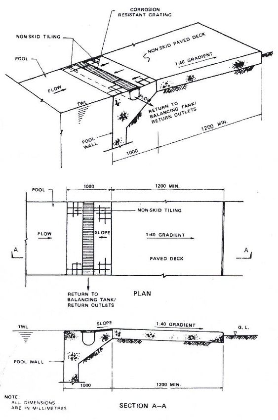
First Edition        1973
                       Second edition        1974
                        Third edition        1974
                       Fourth edition        1978
                         Fifth edition       1986
                        Sixth edition        1988
                      Seventh edition        1990
                       Eighth edition        1998
                        Ninth edition        2005
                        Tenth edition        2013
                      Eleventh editon        2015
                       Twelfth edition       2016
                     Thirteenth edition      2017
                     Fourteenth edition      2020
                      Fifteenth edition      2021

No Part Of This Book May Be Reproduced In Any Form Without The Written Permission
                       Of The National Environment Agency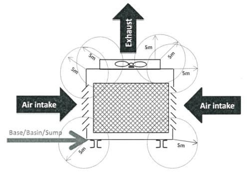
CONTENTS

                                                            Page
INTRODUCTION                                                  i

BUILDING PLANS REQUIREMENTS
Section
  1   Refuse Storage and Collection System                   1
  2   Public Toilet                                         10
  3   Ventilation, Ducting and Kitchen Exhaust Systems in   15
      Food Shop
  4   Cooling Tower                                         17
  5   Aquatic Facility                                      18
  6   Storage and Collection System for Recyclables at      23
      Strata-titled Properties with Residential Units
  7   Anti-Mosquito Breeding                                26

APPENDIX
  1   Example of Layout of Bin Centre                       27
  2   Provision of Sanitary Facilities                      30
  3   Details of Deck Level Channel                         34
  4   Example of 5 m Setback Measurement of a Cooling       35
      Tower
  5   Glossary of Terms                                     36
Code of Practice on Environmental Health (2021 Edition)
INTRODUCTION
The Code of Practice on Environmental Health (COPEH) provides the
guidelines to address environmental health concerns in the design of
buildings. The Code spells out the objectives to be met and stipulates only
the minimum basic design criteria. In this way, Qualified Persons (QPs:
Architects or Professional Engineers) may exercise flexibility and creativity
in the design to meet the stated requirements without compromising
functional and maintenance needs. So long as design outcomes satisfy
the stated objectives, the building plans will be deemed to have complied
with the COPEH. Notwithstanding this, the QP shall be fully responsible
for safety, effectiveness and all other aspects of the design.
Director-General of Public Health
National Environment Agency
Singapore
iCode of Practice on Environmental Health (2021 Edition)
1 REFUSE STORAGE AND COLLECTION SYSTEM
1.1 Objective
The refuse storage and collection system shall be mechanised where possible and
designed so as not to cause nuisance to occupants and neighbouring premises, and to
prevent pollution to the environment. All facilities provided shall be adequately sized to
meet the anticipated refuse output.
1.2 Refuse Output
(a) The refuse output for the various categories of premises shall be computed as
follows:
Category of Premises Refuse Output (litres/day)
Office 15 per 100 sq m gross floor area
Hotel / dormitory 10 per 100 sq m gross floor area
Shop / trade premises 30 per 100 sq m gross floor area
Supermarket / market 100 per 100 sq m gross floor area
/department store
Restaurant / eating house 200 per 100 sq m gross floor area
/food centre / canteen
Residential premises 20 per dwelling premises
Petrol station 300 per premises
(b) Where a proposed development has a combination of different types of premises
(for example, a shopping complex with offices, residential premises and a food
centre), the total refuse output shall be the sum of the outputs of each category
of premises.
1.3 Refuse Chute
Refuse chutes shall be provided for residential buildings and buildings with residential
component taller than four (4) storeys so that occupants need not have to bring their
refuse into lifts or walk down the stairs with it. Refuse chutes shall meet the following
requirements:
(a) The refuse chute shall be made of reinforced concrete with cross-sectional area
of at least 0.3 sq m.
(b) The chute shall terminate at the roof of a building. The chute shall be ventilated
at the top with at least two openings of not less than 0.1 sq m each. This top
section of the refuse chute shall be accessible from the common area to facilitate
maintenance.
(c) If the roof is to be used as a roof terrace/garden, particular attention shall be paid
to the siting of the refuse chute, the location of its openings and the maintenance
requirements so as not to cause any smell nuisance. Ventilation openings shall
be located at least 2.1 m above roof level.
1Code of Practice on Environmental Health (2021 Edition)
(d) There shall be a system to wash and flush the whole length of the chute. The
control valve for the flushing system is preferably located at the chamber level.
The system shall be designed for manual activation of flushing and automatic de-
activation.
(e) Where a centralised refuse chute is provided, the hopper shall be sited as far
away as possible from residential dwelling units and not be facing the entrance
of the units. The hopper shall be screened when this requirement cannot be
achieved.
A refuse chute chamber or room shall be built at the bottom of the refuse chute. As the
refuse chambers are smaller than refuse room, a refuse bin point or refuse bin centre
with additional storage for the refuse shall be provided within the development. The
refuse collection vehicle collects the refuse from the bin point or bin centre. Conversely,
refuse rooms are larger than refuse chamber and designed with the full refuse storage
capacity, and refuse is collected directly from the refuse rooms by refuse collection
vehicle.
1.4 Refuse Chute Chamber
The refuse chute chamber shall be suitably located to facilitate easy and nuisance-free
conveyance of refuse. The refuse chute chamber shall meet the following requirements:
(a) The chamber shall be designed to house a SS EN-840 standard wheeled refuse
bin which can contain at least one (1) day of refuse output from all the premises
connected to the chute. The refuse bin shall have a maximum capacity of 660
litres. In the event where it is not possible to provide storage for one day of refuse
output even with the largest 660-litre bin, the refuse in bin shall be cleared more
frequently as required to prevent spillage of refuse within the refuse chamber.
However, the total daily refuse output from all the premises connected to the
chute shall not exceed 1,980 L.
(b) The refuse chute chamber’s walls shall be lined with tiles or other smooth,
impervious materials.
(c) The refuse chute chamber’s floor shall be recessed at least 100 mm below the
apron area and graded towards a gully connected to a sewer.
(d) The maximum gap between the termination point of the refuse chute and the top
of the refuse bin shall be 200 mm.
(e) An airtight non-corrosive flap door shall be provided for access to the refuse chute
chamber.
(f) A refuse bin point or refuse bin centre shall be provided. The combined refuse
storage capacity of the bin point or bin centre and all the refuse chute chambers
shall be sufficient for at least two (2) days of refuse output of the development.
1.5 Refuse Room
The refuse room shall house a mechanical refuse handling equipment, e.g. a dust-screw
or any other enclosed fixed system. Refuse collected in the refuse handling equipment
2Code of Practice on Environmental Health (2021 Edition)
is conveyed directly into a refuse collection vehicle, which backs up into the refuse room.
The refuse room shall meet the following requirements:
(a) The refuse room shall be large enough to accommodate two (2) days of refuse
output from all the premises connected to the refuse chute.
(b) The vehicular service road to the refuse room shall be free from obstruction and
such that the refuse collection vehicle can make a three-point turn within the
premises to back up into the refuse room. To facilitate this, the refuse room floor
and vehicular service road shall be of the same level with a setback distance of
at least 13 m in front of the refuse room. The swept path of the refuse collection
vehicle shall meet the minimum required turning radius of 9 m and the distance
required to reverse into the refuse room shall also be minimised.
(c) The refuse room’s walls shall be lined with smooth tiles or other smooth
impervious materials.
(d) The refuse room’s floor shall be graded towards a gully/floor trap connected to
the sewer.
(e) A water tap shall be provided in accordance with the latest Public Utilities (Water
Supply) Regulations and Singapore Standard 636: Code of Practice for Water
Services. The water tap shall be securely locked to prevent unauthorised use.
(f) The refuse room shall be rendered pest-proof against birds, rodents and insects.
(g) The refuse room shall be provided with a roller shutter door with a clear width of
3.4 m and clear height of 4 m.
1.6 Refuse Bin Point and Refuse Bin Centre
Developments not adopting the Refuse Room system i.e. those with or without refuse
chambers shall be provided with either a bin point or a bin centre within the premises.
Refuse collections shall be carried out only from within the premises. A bin centre shall
be provided if refuse output exceeds 1,000 litres/day.
For developments adopting the Refuse Chute Chamber system, the combined refuse
storage capacity of the bin centre or bin point and the refuse chute chambers shall be
sufficient for at least two (2) days of refuse output of the development. For developments
without refuse chute chambers, the bin centre or bin point capacity shall be sufficient for
at least two (2) days of refuse output of the development.
The bin centre shall meet the following requirements:
(a) The bin centre shall be sited so as not to cause a nuisance to neighbouring
premises, and be accessible to a refuse collection vehicle. An adequate turning
area shall be provided where necessary to accommodate the various sizes of
refuse collection vehicles available in the market. Refuse collections shall be
carried out only from within the premises.
3Code of Practice on Environmental Health (2021 Edition)
(b) The bin centre shall be designed for access of SS EN-840 standard wheeled bins
from within the development. Sufficient space shall be provided for washing and
manoeuvring of refuse bins within the bin centre.
(c) The bin centre’s walls shall be lined with smooth tiles or other smooth, impervious
materials.
(d) The bin centre’s floor shall be graded towards a gully/floor-trap connected to the
sewer.
(e) The bin centre shall be provided with a roof with no gutters. The roof shall have
an adequate gradient to prevent water stagnation and mosquito breeding.
(f) The bin centre shall be adequately ventilated and rendered pest-proof against
birds, rodents and insects.
(g) The bin centre’s entrance and ventilation openings shall face away from any
residential premises in the vicin ity. Aesthetic screening shall be provided where
practical, so as not to cause a nuisance to neighbouring premises.
(h) An access walkway of at least 1 m clear width around all items in the bin centre
shall be provided.
(i) Where the daily refuse output of the premises is less than 4,000 litres, SS EN-
840 wheeled bins can be used for storage of refuse in the bin centre.
(j) Where the daily refuse output of the premises is 4,000 litres or more, an enclosed
roll-on roll-off (RORO) compactor/container, dust screw compactor or a rotary
drum system shall be provided. The type of system to be provided depends on
the refuse composition and the amount of refuse output from the premises. The
RORO compactor/container provided shall be designed in accordance with DIN
30722. The following additional design requirements of the bin centre shall apply:
i. The required roller shutter opening of the bin centre shall be 4 m (clear width)
by 5 m (clear height).
ii. A 5 m clear height shall also be provided in front of the entrance when a
RORO compactor/container or any other refuse storage system that requires
haulage is provided.
iii. A setback distance of at least 13 m shall be provided to ensure that the bin
centre is accessible to refuse collection vehicles. The swept path of a refuse
collection vehicle from the main or service road to the bin centre shall meet
the minimum required turning radius of 9 m and also be free of obstructions.
iv. The bin centre floor level shall be at the same level as the vehicular access
road and the RORO compactor/container shall be resting on the bin centre
floor.
v. The distance for refuse collection vehicles to reverse into the bin centre shall
be minimised. A guide of the layout of a bin centre is shown Appendix 1A.
4Code of Practice on Environmental Health (2021 Edition)
vi. If bin lifter is used, there shall be sufficient space to enable the bin lifter to
operate the bin properly.
vii. When there are more than 1 RORO compactor/container in the bin centre,
the minimum separation between the adjacent compactor/containers shall
be 0.5 m.
viii. The orientation of RORO compactor/container’s tail gate shall face the inside
of the bin centre.
ix. Floor markings shall be provided in front of the entrance of the bin centre to
guide the refuse collection vehicle when reversing during operation.
Where a bin point is provided, washing points and water taps are not required and the
bin point need not be connected to the sewer. The bin point shall have a pleasant
architectural appearance and be sited so as not to cause a nuisance to neighbouring
premises.
1.7 Pneumatic Waste Conveyance System (PWCS)
All new strata-titled properties with 500 or more residential dwelling units for which
development applications are submitted to URA from 1 April 2018 onwards shall be
provided with a PWCS. Applicants shall provide a copy of URA’s Provisional Permission
in their DC application to NEA.
Where a PWCS (i.e. stationary vacuum system or vacuum truck system) is provided,
the following requirements shall be complied with:
(a) For refuse chute which are square, the cross-sectional area of the chute shall be
not less 0.3 sq m. For refuse chute which are round, the minimum internal
diameter of the chute should not be less than the diameter of 600 mm. The refuse
chute shall be made of reinforced concrete material.
(b) The opening of the chute hopper is to be fully volume-controlled to restrict large
or long items from entering the chute (see Appendix 1B). The chute hopper shall
be adequately sized to accommodate bagged waste of size 300 to 350 mm
measured in any angle. These features will allow the disposal of bagged waste
of typical sizes, and prevent oversized waste from choking the hopper and the
chute.
(c) Sensors and monitoring equipment shall be provided to monitor the refuse
collected at the refuse chute and activate the discharge cycle to convey the refuse
to the bin centre to prevent excessive piling of refuse within the refuse chute.
(d) Inspection openings shall be provided at intervals of not more than 50 m along
straight sections, and at locations of the PWCS conveyance pipe network where
refuse is likely to accumulate and block the conveyance pipe, including, but not
limited to, pipe connections and bends in the conveyance pipes.
(e) The ventilation, air intake and air outlet units shall be sited so as not to cause any
noise or smell nuisance to neighbouring premises or residents of the premises
served by the PWCS.
5Code of Practice on Environmental Health (2021 Edition)
(f) The system shall be designed so as not to cause any noise nuisance to residents
of the premises served or neighbouring premises when it is operated.
(g) Dust and odours shall be removed from the air that conveys the refuse before
the air is discharged into the atmosphere. Measures to remove dust and odours
include, but are not limited to the following:
i. Dust and deodorising filters shall be provided to filter dust and foul odours
from the air conveying the refuse before the air is discharged to the
atmosphere.
ii. The type and quantity of filters provided shall be appropriate and sufficient
to treat all air exhausted from the PWCS system.
iii. The filters shall efficiently filter the air without affecting system performance
and in an energy efficient manner.
iv. All filter media shall have a life span of no less than six (6) months between
replacements.
v. In addition to the filters, an Odour Treatment System shall be provided to
treat the air such that the discharged air from the exhaust air outlet or bin
centre does not cause smell nuisance to residents.
The discharge point shall also be located at the highest level possible and pointed
away from residential dwelling units and commercial spaces within and
surrounding the development.
(h) A PWCS bin centre shall be provided for stationary systems. The PWCS bin
centre shall be designed to meet the same requirements stated in Section 1.6.
The refuse storage capacity in the bin centre shall be sufficient for storage of at
least two (2) days of refuse output of the development. The PWCS refuse
container shall be designed in accordance with DIN 30722.
(i) For vacuum truck systems, the size of the intermediate storage area shall be
sufficient for the storage of at least two (2) days of refuse output. The
requirements stated in Section 1.6 shall still apply so that a proper storage facility
within the development is available in the event that the vacuum truck is not
available for collection.
(j) The bin centre shall be accessible to refuse collection vehicles, and be so sited
so as not to cause nuisance to neighbouring premises. The design requirements
for the bin centre as stated in Section 1.6 (j) shall still apply.
(k) A communications system shall be incorporated into the system to automatically
and immediately alert the management and appointed service provider of any
faults or breakdowns detected in the system so that repair work can be promptly
arranged.
(l) The complete system including the exhau st air treatment system shall be
designed for ease of maintenance.
6Code of Practice on Environmental Health (2021 Edition)
(m) The electrical and electronic components (including the Programmable Logic
Controller) shall use Original Equipment Manufacturer (OEM) parts.
(n) The design of the PWCS shall comply with the latest Singapore Standard SS
642: Code of Practice for Pneumatic Waste Conveyance System.
1.8 Mandatory Waste Reporting Scheme
Developments required to report their waste data may make their own provisions to
weigh their refuse by installing in-house weighing systems e.g. by fitting their dust drum
system with load cells and weighing system. Alternatively, they may engage the services
of general waste collectors who may provide weighing records from on -board truck
weighing systems or weighbridge records from incineration plants.
1.9 Location of Grease Trap
(a) Grease trap shall be installed and sited at suitable location that allows for easy
access to facilitate maintenance, not give rise to public health, noise and hygiene
problems during operation and maintenance, and be accessible for the transfer
of greasy waste directly into Class C waste collection trucks without double
transfers. Road access and vehicle parking shall be made available within the
development for the Class C waste collection trucks so that the collection trucks
are not more than 10 m away from the grease traps to facilitate suction of the
greasy waste into the trucks’ waste collection tanks.
(b) For food shop located in development with no internal access roads, the grease
traps shall be located close to external road access with vehicle parking for the
temporary stationing of Class C waste collection trucks not more than 10 m away
from the grease traps.
(c) Where portable greasy trap is permitted and installed within the food shop, road
access and vehicle parking shall be made available for the Class C waste
collection trucks to be not more than 10 m away from the building in which the
food shop is located.
1.10 On-Site Food Waste Treatment System
All new commercial and industrial premises that meet the thresholds stated in the table
below are required to allocate space for on -site food waste treatment system. The
requirements shall apply to new development applications submitted to URA from 1
January 2021 onwards. Applicants shall provide a copy of URA’s Provisional Permission
in their DC application to NEA.
7Code of Practice on Environmental Health (2021 Edition)
Types of premises Thresholds (Gross Floor Area)
Shopping Malls F&B Area1 > 3,000 sq m
Commercial
Hotels Function + F&B Area >3,000 sq m
Large food manufacturers2 (i.e. Operation area >
750 sq m)
Premises which are solely used for specific trade
Single User
activities3 can be excluded from the requirement. An
Factories
exemption request along with the necessary
(SUFs)
documents shall be submitted to NEA for checks.
Elaboration shall also be provided to support their
request when required by NEA.
Industrial
At least 1 large food manufacturer (i.e. Operation
area > 750 sq m)
Multi-User
Or
Factories
(MUFs)
GFA > 20,000 sq m and > 20 food tenants (i.e. food
manufacturers and food caterers)
Building plans of all affected premises shall be submitted. The plans shall clearly
demarcate the allocated area for on-site food waste treatment system.
Premises where homogenous food waste is segregated for recycling into animal feed
may be exempted from the requirement to set aside space for on -site food waste
treatment. An exemption request along with the necessary documentations shall be
submitted to NEA for verification.
The space set aside for on-site food waste treatment must meet the following
requirements:
(a) The space shall be sited in the building or within the premises on which the
building is situated. Possible areas include the refuse bin centre or a dedicated
food waste treatment room.
(b) The size and layout of the space set aside shall be designed to support the
implementation of the on-site food waste treatment system including:
i. For mandated premises (i.e. premises that meet the respective thresholds
stipulated in the Resource Sustainability Act), the minimum space required
for the on-site system, including space for service and maintenance works
of the treatment system and access of SS EN-840 standard wheel bins is 25
m2 (e.g. 5.0 m by 5.0 m for a square space). For all other premises, the space
to be set aside will depend on the specific on-site system to be installed.
1 Gross f loor area set aside f or supermarkets located in shopping malls will count towards the computation of F&B
area of said shopping malls.
2 As licensed under Singapore Food Agency’s Licence to operate a f ood processing establishment
3 Manuf acturer of spices, dried f oodstuffs, additives, bottled water, high pressure processing
8Code of Practice on Environmental Health (2021 Edition)
ii. If a bin lifter system is employed, there shall be sufficient height clearance to
enable the bin lifter to handle the bin properly.
(c) Where the space is located within the refuse bin centre, the space set aside for
said food waste on-site system shall concurrently comply fully with requirements
outlined in Section 1.6.
(d) Provisions shall be made for the effluent (if any) from the food waste treatment
system to be discharged into the sewer through a grease trap.
(e) Where a dedicated food waste treatment room is provided, the following
additional design requirements shall apply:
i. The floor shall be graded towards a gully connected to the sewer.
ii. The room shall be adequately ventilated and rendered pest proof against
birds, rodents and insects.
iii. The room shall not pose any pest or odour nuisance or any pollution
concerns to occupants, neighbouring premises and/or the public.
iv. Additional space for a washing point to wash refuse bins. The water tap
provided for washing shall be in accordance with the latest Public Utilities
(Water Supply) Regulations and Singapore Standard 636: Code of Practice
for Water Services.
v. The entrance and ventilation openings/exhaust discharge shall face away
and be aesthetically screened from any neighbouring premises in the
vicinity.
9Code of Practice on Environmental Health (2021 Edition)
2 PUBLIC TOILET
2.1 Objective
The public toilets shall be designed to withstand heavy usage. Ventilation is therefore
important. The design shall also take into consideration ease of maintenance and should
facilitate proper toilet use and personal toilet hygiene. There shall be adequate provision
of toilet facilities for premises provided with public toilet. Owners/occupiers should
ensure that sanitary and water fittings, amenities and ventilation systems are adequately
maintained.
2.2 Definition of Public Toilet
2.2.1 A public toilet is defined as a toilet within premises which the general public has free
access, regardless of payment/ non -payment to access the premises. The general
public is free to access the public toilet without having to be a resident, student, staff,
member or a guest, or a regular client. Toilets in the following places are classified as
public toilets:
shopping mall or centre, including the floor in commercial buildings with shops;
supermarket and wet market;
eating establishment and food centre (restaurant, coffeeshop, hawker centre, food
court)/ bar/ nightclub/ discotheque/ pub;
conference hall/ cinema/ theatre/ convention hall/ exhibition hall;
park/ park connector;
bus terminal/ interchange;
petrol station;
MRT station;
stadium; and
public swimming pool.
QPs are also encouraged to adopt the guidelines stipulated within, for toilets within
premises without free access to the general public (e.g. condominiums, terraced
workshops, places of worship, etc.).
2.2.2 Although construction sites are not freely accessible to the public, sanitary facilities in a
construction site shall be provided in accordance with the requirements stipulated in
Appendix 2.
2.3 General Design Criteria
The general design requirements for public toilet shall be as follows:
(a) Wall finishes shall be of materials which are impervious and durable such as
ceramic tiles and phenolic panels to facilitate cleaning.
(b) Floors shall be constructed of waterproof non -slip surfaces like ceramic tiles,
natural stone, homogeneous tiles or other impervious materials to facilitate
cleaning.
(c) The toilet’s main entrance shall preferably have no door and with a labyrinth
entrance, and the cubicles, urinals and mirrors shall be away from the line of sight
10Code of Practice on Environmental Health (2021 Edition)
from the main entrance. Toilets with sufficient space that are unable to
incorporate labyrinth entrances are recommended to install hands-free or sensor-
operated doors.
(d) The minimum lighting level shall be 300 lux to ensure that areas with water
closets, wash basins and urinals are sufficiently illuminated. QPs should
incorporate the usage of natural lighting where feasible, e.g. outdoor venues, top
floor of buildings with open concept, etc.
(e) All toilet cubicles shall be at least 900 mm wide and 1500 mm deep.
(f) Cubicle partitions shall be of rigid design and wall or ceiling hung, where practical,
without leg support for easy cleaning of the floor.
(g) Design symmetrical layout concept for toilet, where space is available, so as to
reduce disruption to toilet usage during cleaning maintenance e.g. allow half of
the toilet to be closed for maintenance while keeping the other half open for use.
2.4 Sanitary and Water Fittings Required in Public Toilet
Sanitary and water appliances and fittings installed in public toilets shall be of heavy-
duty classification and quality and shall be easily-cleaned. Water fittings shall comply
with the relevant standards and requirements stipulated under the latest PUB S&R*, and
their installation shall be in accordance with the latest Public Utilities (Water Supply)
Regulations and Singapore Standard 636 – Code of Practice for Water Services. For
water fittings and appliances covered under PUB’s Mandatory Water Efficiency
Labelling Scheme, only models which are registered under the Scheme shall be
installed. The PUB S&R and list of registered MWELS products can be found in PUB’s
website at www.pub.gov.sg. This includes the amount of water per flush in urinals and
water closets, waterless urinals, flow rate for self-closing delayed-action sensor type
taps etc.
Where sanitary and water provisions are to be made for persons with disabilities and
families with young children, such provisions shall be in accordance with the
requirements stipulated in BCA's “Code on Accessibility in the Built Environment”.
Sanitary facilities for premises are to be provided in accordance with the requirements
stipulated in Appendix 2. These facilities provided are over and above the BCA's
requirements with regard to the provisions of accessible toilet, family toilet, child-friendly
toilet and child-friendly wash basin.
A glossary of the terms used in this section is given in Appendix 5.
*PUB’s Stipulation of Standards & Requirements for Water Fittings for Use in Potable
Water Service Installations.
2.4.1 Number of sanitary fittings
(a) The number of public toilets and sanitary fittings to be provided in buildings
accessible to the general public is given in Appendix 2. The numbers of facilities
provided are minimum requirements and QPs should design the toilets to ensure
sufficient facilities are provided based on the expected toilet use during peak
hours.
11Code of Practice on Environmental Health (2021 Edition)
(b) Owners/occupiers should also provide sufficient sanitary facilities based on
anticipated usage, for toilets that fall out of the categories of places mentioned in
Appendix 2.
(c) Where there are public toilets within the building where a food shop is located,
the provision of a toilet within the food shop is not necessary. Otherwise, the
number of toilets and sanitary fittings provided shall be in accordance with the
requirements in Section 2 and Appendix 2.
2.4.2 Water closets
(a) Pedestal type water closets shall preferably be wall hung, without leg support, so
as to facilitate cleaning.
(b) Each water closet shall be fitted with a sensor-operated flush valve and coupled
with manual by-pass and manual override.
(c) A water closet with a bidet fixture shall be provided within at least one cubicle of
the toilet.
(d) For cubicles where water closets with bidet fixtures or water tap points with spring
loaded nozzle are provided, the cubicle floor shall be properly graded towards
the gully/floor trap within the cubicle. Scupper drains with metal grating shall
preferably be installed within the cubicle to facilitate the draining off of water. For
such cubicles, there shall be signage on the cubicle door indicating the provision
of the water closet with a bidet fixture. Signage is not required for toilets where
all cubicles are provided with the water closet with a bidet fixture.
2.4.3 Urinals
(a) Each urinal shall be fitted with a sensor-operated flush valve with manual override
feature.
(b) Where a waterless urinal is installed, it shall be maintained in accordance with
manufacturer’s instructions and not cause any odour nuisance.
(c) There shall be a scupper drain underneath the urinals along the wall where
urinals are installed, to facilitate the removal of dripping during cleaning of the
floor. The width of the scupper drain should not be more than 150 mm.
(d) Individually wall-hung full length urinal units shall be installed to facilitate use for
different users and to reduce urine drip onto floors. It shall be at least 300 mm
wide and the lip of the collection area shall project from the wall by at least 300
mm.
2.4.4 Wash hand basins and taps
(a) Wash hand basins shall be installed such that there is sufficient gradient to allow
dirty and debris to be effectively washed into the drain pipes. Flat-bottomed
basins should not be installed.
(b) Wash hand basins shall be under-counter. Other designs are allowed, provided
that they can minimise the problem of water spilling over from the basin to the
12Code of Practice on Environmental Health (2021 Edition)
counter. For basins that sit on top of the counter or are stand-alone, these shall
be deep enough to prevent water splashing out of the basins when in use. The
water discharge point from the wash hand basin tap shall also be of a sufficient
height above the bottom of the wash hand basin to prevent contact of hands with
the basin.
(c) All wash hand basin taps shall be sensor taps with self-closing delayed-action
feature with flow rate of 2 litres/min (with tolerance of ±0.2 litre/min) and a fixed
pre-set flow timing of 60 seconds (with tolerance of ±5 seconds) and water supply
shall be automatically cut-off when hands are moved away from beneath the tap,
whichever is earlier. To ensure that one tap remains functional during power
supply outage, one tap per toilet block shall be a battery-operated or chargeable
battery-operated sensor type tap.
For toilet block provided with only one wash hand basin, only a self -closing
delayed-action mechanical type tap shall be installed.
(d) Wash hand basins should also be provided for public toilets located at common
areas.
(e) In food retail outlets where toilet facilities are provided, wash hand basins shall
preferably be provided outside the toilet. Wash hand basin taps shall comply with
the requirements in clause c of Section 2.4.4 of the COPEH.
2.5 Amenities to be Provided
(a) Liquid soap or foam soap dispenser
One soap dispenser shall be provided for every two count of wash hand basins,
subject to a minimum of one. The dispenser shall be positioned directly above
and at least between every two wash hand basins. The dispenser shall have a
transparent window so that the level of soap in the dispenser is clearly visible.
The soap dispenser shall be filled with liquid or foam soap at all times.
(b) Hand-dryer blower or paper towel dispenser
One electronic hand-dryer or paper towel dispenser shall be provided for every
two count of wash hand basins, subject to a minimum of one. The electronic
hand-dryers shall be positioned immediately next to the wash hand basins where
practical, and located away from toilet cubicles. Where paper towel dispensers
are provided, they shall be positioned directly above and at least between every
two wash hand basins. Paper towel dispensers are recommended in toilets
frequented by immuno-deficient persons and where infection control is critical.
(c) Litterbins
A minimum of one litterbin shall be provided directly below or in close proximity
to the wash hand basins. A separate sanitary bin for the disposal of sanitary pads
shall be provided in each WC cubicle in the female and unisex toilets. Bins shall
always be covered and operated without hand contact e.g. foot pedal or
electronic motion sensor devices.
13Code of Practice on Environmental Health (2021 Edition)
(d) Toilet paper holder
A jumbo paper toilet roll holder or a toilet tissue dispenser of similar capacity shall
be installed in each WC cubicle.
(e) Cleaner’s sink with tap-point
A dedicated sink with tap-point for maintenance personnel to clean public toilets
shall be provided within or in close proximity to each toilet block, where practical.
2.6 VENTILATION
(a) The toilet shall be well-ventilated by natural or mechanical means to remove
odours and to keep floors dry. Where mechanical means are used (i.e.
extractor/exhaust fan), the air exchange rate shall have a minimum of 20 air
changes per hour. Service access ducts, if fully enclosed, shall be connected to
the mechanical ventilation system. Ventilation for toilets with natural ventilation
shall be provided by means of one or more openable windows or other openings
with an aggregate area of not less than 5 % of the floor area of the toilet.
(b) The exhaust system shall dispel the air directly outdoors without causing any
nuisance to neighbouring premises.
Note: While this Code stipulates the minimum basic design criteria, QPs are encouraged
to refer to Restroom Association (Singapore)’s publication for further reference on good examples of toilet design.
14Code of Practice on Environmental Health (2021 Edition)
3 VENTILATION, DUCTING AND KITCHEN EXHAUST SYSTEMS FOR
FOOD SHOP
3.1 Objective
This section addresses the design criteria for kitchen exhaust ducting and systems of
foodshop(s) at building plan and pre-operation (pre-licensing) stages.
3.2 Design Requirements
Qualified Person(s) shall adopt the following design siting requirements at building plan
stage.
(a) The fumes from the kitchen exhaust system shall be exhausted above the roof
and not face in the direction of adjacent buildings. Where it is not practical to
exhaust the fumes at or above the roof, an alternate location of the discharge
point in the outdoors may be selected, and not face in the direction of adjacent
buildings.
(b) Consideration shall be given to aesthetic aspect of the exhaust outlets,
particularly when it is sited near residential premises. Suitable aesthetic screen
design shall be provided to screen off the kitchen exhaust duct and exhaust
outlets from view of nearby neighbouring premises and the public.
(c) Kitchen exhaust outlets shall be sited more than 5 m from all edges or structures
of cooling towers.
3.3 Operations Requirements
Licensee(s) shall ensure the following requirements are met in accordance to the pre-
licensing requirements, prior to operations.
(a) All fumes from the cooking range shall be extracted immediately and treated with
an air cleaning system. The air cleaning system shall capture particulate matters,
grease, oil and water vapour with no visible smoke and fumes exhausting.
(b) The treated air is to be exhausted outdoors by a hood and flue or other extractor
fan system above the roof and not face in the direction of adjacent buildings.
Where it is not practical to exhaust the fumes at or above the roof, an alternate
location of the discharge point in the outdoors may be selected, and not face in
the direction of adjacent buildings.
3.4 Other Requirements and Guidelines
The following are references(*) for Qualified Persons and licensees to refer to.
(a) Singapore Civil Defence Force’s Code of Practice for Fire Precautions in
Buildings: The entire (interior and exterior) exhaust duct and kitchen hood shall
be degreased and cleaned at least once every 12 months. The work shall be
carried out by a specialist and the records of cleaning and degreasing shall be
kept by the owner/operator for verification by the authority having jurisdiction.
15Code of Practice on Environmental Health (2021 Edition)
(b) Singapore Standard’s SS 553: Code of Practice for Air-Conditioning and
Mechanical Ventilation in Buildings: Guidelines on kitchen ventilation and
maintenance of kitchen exhaust system.
(*): As the descriptions/requirements/guidelines may be subjected to change, the Qualified
Person(s) and licensees should always refer to the prevailing regulatory requirements, code of
practices, standards and guidelines.
16Code of Practice on Environmental Health (2021 Edition)
4 COOLING TOWER
4.1 Objective
This section serves to provide the minimum design criteria for siting of cooling towers at
building plan submission.
4.2 Design Requirements
A qualified person (QP) shall ensure the following design siting requirements are
complied with.
(a) The cooling tower shall be located at least 5 m from any air circulating and
ventilating inlet, openable window and occupied area, pedestrian thoroughfare,
trafficable area and any other areas of public access.
(b) The cooling tower shall also be located at least 5 m from any kitchen exhaust
discharge outlet, air handling system or other areas where nutrients conveyed
from these systems could assist in the growth of Legionella bacteria in the cooling
tower system.
(c) On the measurement point for the minimum 5 m setback distance, this 5 m
distance shall include measurement from the nearest edge or structure of the
cooling towers, including the base/basin/sump, packing exhaust and outlet point
of exhaust hood, if any is installed. Please see Appendix 4 for a typical example
showing the 5 m setback measurement.
(d) All access routes such as doorways leading to the areas that is within the 5 m
setback distance of the cooling towers, should have a clear signage to inform
and deter public from entry and accessible only by cooling tower maintenance
staffs who understand the risk of Legionellosis and will work in accordance to
their safe work procedures based on their risk assessment done.
17Code of Practice on Environmental Health (2021 Edition)
5 AQUATIC FACILITY
5.1 Objective
This section serves to provide the minimum design criteria to address public health
concerns for regulated aquatic facilities (AF). The AF shall be designed such that the
water quality will always comply with regulated limits at all times. The AF include:
(a) Swimming Pool: An artificial pool which operates with a water recirculation
system, intended primarily for swimming, diving, wading, or dipping but does not
include a reservoir or a pond.
(b) Water Playground (including interactive water fountain): A recreation area
installed with artificial water features that operate with a water recirculation
system designed for play and interaction.
(c) Multi-use Spa Pool: An artificial pool which operates with a water recirculation
system, and utilises hydrojet circulation or air induction bubbles. This includes
hydrotherapy pools, hot tubs, Jacuzzis and onsen pools where water is
recirculated after use each time, and is not drained out.
As AF users’ safety components do not form part of the Minimum Design Criteria, please
refer to Singapore Standard SS 556: Code of Practice for the Design and Management
of Aquatic Facilities for guidance on the safety components for AF.
5.2 Minimum Design Criteria
The AF system shall be sized in accordance to the volume and estimated maximum
bather load. Water in the AF shall be circulated through a filtration system which
produces water that comply with regulated limits prior to its return to the AF.
The minimum design criteria for AF (Swimming Pools, Water Playgrounds (including
Interactive Water Fountains) and Multi-use Spa Pools) can be classified into the
following 2 categories:
(a) Minimum design requirements to be declared by QP to comply with on building
plan (BP), and
(b) minimum design requirements to be considered by QP to allocate and indicate
the space on BP to install required equipment and declared by QP that they will
adhere to requirements for equipment specifications.
5.2.1 Aquatic Facilities
The minimum design criteria that QP should take note are:
(a) The AF system shall consist of pumps, filters, automated chemical feeders,
perimeter overflow systems/skimmers, valves, pipes, connections, fittings and
appurtenances. These systems shall treat the water in the AF in accordance with
the relevant regulatory requirements. Space shall be catered for installation of
these equipment at building plan stage. If a development has multiple types of
18Code of Practice on Environmental Health (2021 Edition)
AF, the AF shall have filtration and water treatment systems to meet the required
turnover rate of each AF.
(b) AF edges and landscaping shall be of such design and materials to facilitate easy
maintenance and minimise the contamination of water (e.g. accumulation of
debris, etc.). The landscaping to enhance the appearance of the AF shall not be
done to an extent that it can contaminate the water in the AFs or create a problem
for the maintenance of the AF. The design of planting strips(s) close to the edge
of AF shall incorporate measures to ensure no overflow of water or run -off from
the planting strip(s)/ area(s) into the water. A space of at least 1 m along the
perimeter of AF shall be buffered to facilitate maintenance.
(c) For balancing/surge tanks of AF, the following conditions shall apply:
i. Any overflow pipes and air vents installed on the balancing/surge tanks sh all
be properly screened with non-corrodible, corrosion-resistant stainless-steel
mosquito-proof netting of aperture size not exceeding 0.65 mm.
ii. For the makeup water supplied from PUB mains to the tanks, the water
fittings shall not allow any backflow.
(d) Rinse showers shall be situated adjacent to each of the AF to encourage users
to use the rinse shower before entering the AF.
i. For premises with one AF, a minimum of two rinse showers shall be provided
for the AF. Premises with multiple AF shall have a min imum of two rinse
showers for the largest AF (based on pool/splash zone area of AF), and a
minimum of one rinse shower for each additional AF.
ii. A minimum of one rinse shower shall be provided for each standalone water
playground within a premises. Standalone water playground refers to water
playground that does not share the filtration system with any other types of
AF.
iii. The rinse shower water shall drain directly into the sewer system and not
into the AF and the overflow perimeter flow system or splash zone of AF.
iv. It is strongly encouraged to provide signages to direct users to use the rinse
showers before entering the AF.
(e) Surfaces surrounding the AF (e.g. deck, ramps, etc.) shall be free of stagnant
water at all times.
(f) The automated chemical feeder shall be capable of supplying the required
amount of disinfectant to disinfect the AF based on the capacity and maintenance
frequency of the AF. A device to determine rate of flow shall be provided for each
disinfectant feeder and it shall not allow the back flow of water from AF into the
disinfectant container.
(g) Flow meters shall be installed on all recirculation systems and shall be capable
of measuring water flow of 1.5 times the designed flow rate.
19Code of Practice on Environmental Health (2021 Edition)
(h) The water-circulation pumps and motors shall be of adequate sizes to turn over
the entire AF pool water capacity as below:
Type of AF Max Permissible
Turnover Time
Swimming Pool (designed mainly for young children’s 2 h
use*)
Swimming Pool (designed for all other uses) 6h
Multi-use Spa Pool 2h
Water playground (including interactive water fountain) 30 min
* individuals up to age of 5
(i) The filtration plant shall be either the rapid sand, diatomaceous earth, glass,
zeolite or any other filtration system approved by the Director-General of Public
Health. Individual filters shall be designed with necessary valves and piping to
permit isolation of individual filters for repairs or backwashing while other units
are in service.
(j) There shall be at least one standby pump un it and motor to supplement the duty
pump provided in each of the filtration system. Sampling taps shall be provided
at the inlet and outlet pipes of the filter for checking filtration efficiency.
(k) Design of indoor AF and equipment rooms shall be adequately ventilated to
control the level of moisture and trapped chemicals. The minimum ventilation rate
shall be in accordance with the relevant guidelines available within SS 556 Code
of Practice for The Design and Management of Aquatic Facilities on ventilation
in indoor aquatic facilities.
(l) There shall be easy and safe access to the tanks to allow for maintenance and
inspection of the tanks.
(m) A non-corrosive removable catch screen or overflow strainer shall be installed at
all discharged points before the water enters the balancing/surge tank to prevent
large debris from collecting within.
(n) Linkways and bridges across the pool are allowed. Care must be taken in the
design to ensure no overflow of water or, runoff from planting strips on the
linkways and bridges into the pool water.
(o) All materials should be of non-toxic nature, corrosion-resistant, both externally as
well as internally, and able to withstand the water pressure and resistant to
chlorine/bromine content in the system.
(p) If a submerged facility such as a bar is constructed or placed in the pool to provide
food or drinks, a sink connected to a sewer shall be provided.
20Code of Practice on Environmental Health (2021 Edition)
5.2.1.1 Swimming Pool
The minimum design criteria that QP should take note are:
(a) A swimming pool system consisting of pumps, piping, perimeter overflow system,
strainer(s), balancing/surge tank, return inlets, filters, automated chemical feeder
and other necessary equipment shall be provided for complete circulation of the
water through all parts of the pool.
(b) Each pool shall be provided at least 2 recirculation system inlets for the first
15,000 gal or 57,000 L capacity and one additional inlet for every additional
15,000 gal or 57,000 L or less capacity. Locations of inlet fittings shall be
arranged in a way which will allow for uniform circulation.
(c) A perimeter overflow system shall be provided for at least 50% of the perimeter
of the pool and designed such as to avoid water stagnancy. Design of a perimeter
overflow system shall take into consideration the following:
i. It shall allow ease of inspection, cleaning, and repair.
ii. It shall be designed and provided with sufficient drains and piping which will
not allow backflow of water into the pool, and flooding of the overflow
channel.
iii. Water that overflows from the pool shall be recirculated for reuse.
iv. A deck level channel design can be adopted for the perimeter overflow
system. An illustrated example of deck level channel can be found in
Appendix 3.
(d) Surface skimmers can be used where the water surface area is less than 450 m2.
Surface skimmers shall be located in an appropriate position in relation to inlets
to maintain effective skimming action and avoid water stagnancy in the pool. At
least 1 surface skimmer is provided for every 13.5 m2 of water surface area to
maintain effective skimming action throughout the pool. The skimmer system
shall be equipped with auto water top-up devices.
(e) The number of toilets and sanitary fittings provided shall be in accordance with
the requirements in Section 2 of the COPEH.
5.2.1.2 Water Playground
The minimum design criteria that QP should take note are:
(a) A water playground system consisting of pumps, piping, perimeter overflow
system, strainer(s), balancing/surge tank, return inlets, filters, automated
chemical feeder and other necessary equipment shall be provided for complete
circulation of the water through all parts of the water playground.
(b) The splash zone shall be sloped in a way such that only water from the water
playground will flow back to the balancing/surge tank. Areas adjacent to the
splash zone shall be sloped away and downwards from the spray ground to deck
drain or other surface water disposal system.
21Code of Practice on Environmental Health (2021 Edition)
(c) All foggers or misters shall be supplied directly from a potable water source and
not recycled from the balancing/surge tank.
5.2.1.3 Multi-use Spa Pool
The minimum design criteria that QP should take note are:
(a) A multi-use spa pool system shall contain filters, pumps, automated chemical
feeders, pumps or such other systems or devices, to treat the water, aerator/jet
system and other equipment (e.g. heater, etc.).
(b) The perimeter overflow system shall be designed and constructed so that the
water level in the multi-use spa pool is maintained at the operation level of the
rim or weir device.
(c) If surface skimmers are used as the sole overflow system, one surface skimmer
shall be provided for every 13.5 m2. The skimmer system shall be equipped with
auto water top-up devices. When 2 or more skimmers are used, they shall be
located in such a way to maintain effective skimming action over the entire
surface area of multi-use spa pool.
(d) The inlets and outlets shall be arranged in such a way to allow a uniform
distribution of disinfectants throughout the multi-use spa pool.
(e) Multi-use spa pool shall have outlets to drain the water completely for thorough
cleaning purpose (e.g. bottom drains, drain plug, circulatory system, etc.).
(f) The air intake source of air induction system shall be positioned or designed to
(a)
minimise contamination of the multi-use spa pool.
22Code of Practice on Environmental Health (2021 Edition)
6 STORAGE AND COLLECTION SYSTEM FOR RECYCLABLES AT
STRATA-TITLED PROPERTIES WITH RESIDENTIAL UNITS
6.1 Objective
A recyclables storage and collection system shall be installed for strata-titled properties
with residential units so that residents can conveniently recycle their waste. The design
and layout of the system shall not create a nuisance to residents and neighbouring
premises or cause pollution to the environment. A recyclables storage and collection
system can comprise designated recycling points for placing recycling receptacles
and/or a recyclables chute system. The recyclables storage and collection system shall
be adequately sized to meet the anticipated recyclables output without compromising
the refuse storage and collection system.
6.2 Recyclables Output
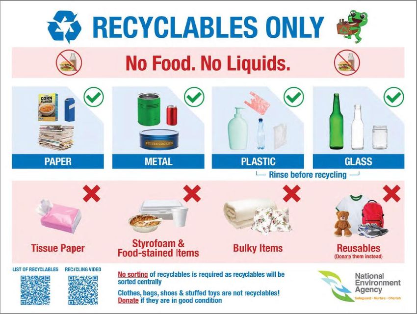
(a) “Recyclables” is defined under the First Schedule of Environmental Public Health
(General Waste Collection) Regulations as follows: -
Recyclables Examples
Paper Newspaper, computer printouts, writing paper, envelopes, car
products park coupons, brochures/pamphlets, magazines, books,
cardboard and paper packaging (such as cereal boxes and
drink cartons) and other paper products but excluding tissue
paper and paper food wrappers
Metal Cans or containers made of metal such as soft drink cans, beer
products cans, milk powder tins and food cans.
Plastic Bottles or containers made of plastic such as detergent
products containers, milk containers, mineral water bottles, soft drink
bottles, juice bottles, plastic bags, plastic packaging and other
plastic products but excluding styrofoam, disposable cutleries
and crockeries.
Glass Jars, wine bottles and beer bottles but excluding light bulbs,
products window glass, porcelain, ceramic and fish tanks.
(b) The daily recyclables output shall be computed to be either an additional 30 %
by volume of the daily refuse output estimated under Section 1.2 or 240 L/d of
recyclables, whichever is higher.
23Code of Practice on Environmental Health (2021 Edition)
6.3 Designated Recycling Points for Recycling Receptacles
All premises shall be provided with a designated recycling point for each residential
block to allow residents to deposit recyclables. The recycling system within the premises
shall meet the following requirements: -
(a) Arrangements shall be made for the consolidation and storage of the recyclables
from the recycling points to a main recycling point. The main recycling point shall
be accessible to a recyclables collection vehicle. The main recycling point shall
allow the placement of bulk bin(s) or container(s) to accommodate the collection
and storage of the minimum daily recyclables output specified in Section 6.2(b).
The main recycling point shall be separate and independent from, and also not
compromise the refuse storage and collection system.
(b) If an enclosed RORO compactor/container, dust screw compactor or a rotary
drum system is provided for storage of recyclables, a setback distance of at least
13 m shall be provided to ensure that the main recycling point is accessible to
recyclables collection vehicles. The main recycling point floor level shall be at the
same level as the vehicular access road. The distance for recyclables collection
vehicles to reverse into the main recycling point shall be minimised.
(c) The capacity of the intermediate recycling receptacles at intermediate recycling
points shall not be deducted from the required capacity (as calculated under
Section 6.2(b)) of the recycling receptacles that are placed at the main recycling
point.
(d) The designated collection point shall not cause any pest and odour nuisance to
estate occupants and occupants of neighbouring premises.
6.4 Recyclables Chute System
All new formal development applications submitted to URA from 1 April 2018 onwards
that are taller than four (4) storeys and for which refuse chutes are required shall also
be provided with separate chutes for recyclables. Applicants shall provide a copy of
URA’s Provisional Permission in their DC application to NEA.
The recyclables chute system shall meet the following requirements: -
(a) A recyclables chute shall be provided next to every refuse chute in the premises.
The recyclables chute shall comply with the same requirements for refuse chutes
stated in Section 1.3. A signage shall be provided above the recyclables chute
hopper to inform users of suitable recyclables to be disposed into the chute. An
example of the signage is shown in Appendix 1C.
(b) A recyclables chute chamber shall be provided. It shall be connected to a
recyclables chute and house a recycling bin. The recyclables chute and its
chamber shall be suitably located to facilitate easy and nuisance-free removal of
recyclables and shall be designed to meet the same requirements as those for
the refuse chute chamber stated in Section 1.4. Its capacity shall be sufficient
for at least one day of recyclables output (as specified in Section 6.2(b)) from all
the premises connected to the recyclables chute. Recyclables deposited in the
recyclables chute chamber shall be consolidated and stored main recycling point
24Code of Practice on Environmental Health (2021 Edition)
for collection. The main recycling point shall comply with the same requirements
stated in Sections 6.3(a) and 6.3(b).
(c) A recyclables collection room shall be built at the bottom of a centralised
recyclables chute to house a large container. Recyclables collected in the
container are transferred to the recyclables collection vehicle. The recyclables
collection room shall comply with the same requirements as those for refuses
room stated in Section 1.5 and a minimum capacity to accommodate two (2)
days of recyclables output.
(d) A pneumatic recyclables chute conveyance system shall comply with the same
requirements that apply to pneumatic waste conveyance systems stated in
Section 1.7. The capacity of the pneumatic recyclables chute conveyance
system shall be sufficient for a minimum of two (2) days of recyclables output.
(e) The complete recyclables chute system shall be designed to minimise pilferage
and/or damage of recyclables.
25You can also read