Information & operations manual for Lagoon 46 Catamaran 2020 'Fly Again'
←
→
Page content transcription
If your browser does not render page correctly, please read the page content below
Information & operations manual for
     Lagoon 46 Catamaran 2020
             ‘Fly Again’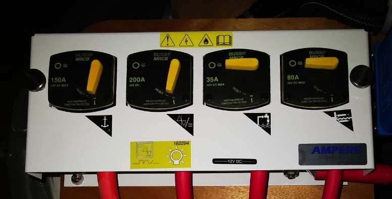
Welcome

Welcome to Horizon Yacht Charters and your Lagoon 42 “Fly Again”. We hope you had a
pleasant journey and are looking forward to a fantastic holiday and some of the finest sailing in
the world here.

This manual is here to guide you through the operation of your yacht. Please take the time to
read this manual and don’t hesitate to ask any of our professional, friendly staff if you have any
questions.

All the yachts in the Horizon fleet are maintained to the highest standards so that you may enjoy
a trouble-free vacation, on a beautiful yacht. Please remember that these yachts are all
privately owned, and we ask that you care for it like it was your own.

Best wishes for a great vacation,

Sylvia and Andrew
Directors

Office Hours:
Monday – Sunday 08:30 – 17:30
Telephone:       (284) 494 8787
Duty Manager:    (284) 542 8788 (Technical questions, damage reports and emergencies)
Contents

1.   Yacht specifications
2.   12-volt and 110-volt panels, breakers and fuses
3.   Inverter
4.   Engine start procedures
5.   Daily engine checks
6.   Generator
7.   Air conditioning
8.   Electronics
9.   VHF procedure
10. Batteries
11. Anchoring and using the windlass
12. Picking up a mooring buoy
13. Bilge pumps
14. Fresh water systems
15. Watermaker
16. Heads
17. Showers
18. Stove and propane
19. Refrigeration
20. BBQ
21. Fire safety
22. Dinghy and outboard
23. Dinghy lift
1. Yacht Specifications

Length      45’11”
Beam        26' 1"
Draft       4' 3"
Fuel        Primary 137 Gallons, Secondary 137 Gallons
Water       X2 79 Gallons
Engines     2 x 57hp Yanmar 4JH 57
Generator   Onan MDKDN-8140A 13.5KW

Location of:
      Engines (starboard and port aft ENG rooms)
      Generator (beneath port bow seating)
      Manual bilge pumps (cockpit both sides)
      Propane tank (FWD cockpit seating)
      Water tank refill (STBD bow)
      Electric winch breaker (STBD aft cabin cupboard)
      Windlass breaker (STBD aft cabin cupboard)
      Diesel refills (port aft cockpit)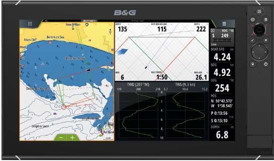
Fuel shut off valves (below the port and starboard aft berths)
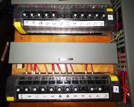
2. The 12-volt panel and breakers

12-volt panel:

12v switches:

Top Row:
Electronics
Navigation Lights
Steaming Light
Deck Floodlight
Anchor Light

Lower Row:
Cabin Lights
Port Primary Bilge Pump (hit once for auto and twice for manual)
Stbd Primary Bilge Pump (hit once for auto and twice for manual)
Fresh Water Pump
Refrigerator

Switches flash if there is a fault. Fuses behind the 12V panel can be reset if there is a
fault.
Breakers and Fuses

                         Fuses Behind 12V Panel

                     Fuses in starboard forward
                     companion way locker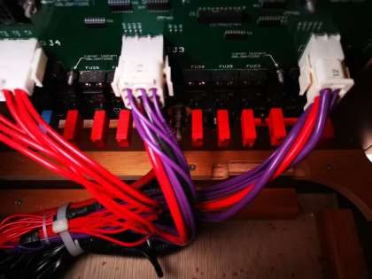
110V/ Shore Power Breakers
behind starboard aft cabin door
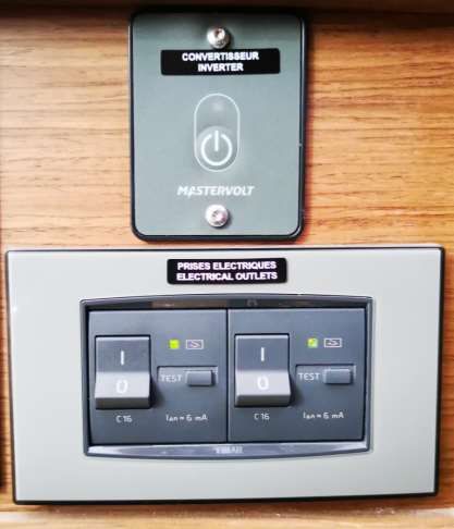
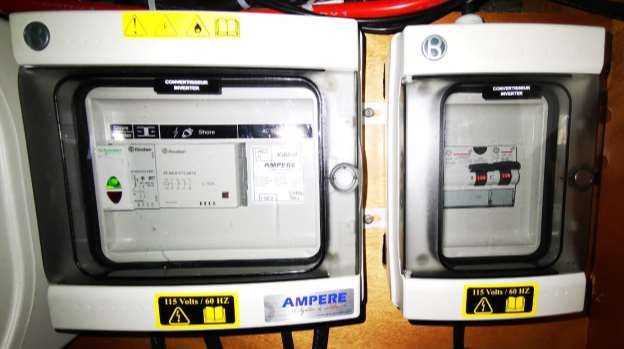
3. Inverter

Warning: Leaving the Inverter turned on will severely deplete the house batteries. For that
reason, it is better to run the engines at the same time. If you have the Generator running
there is no need to use the Inverter.

Fly Again is equipped with a built-in Mastervolt 2000-Watt power inverter that allows you to
have access to all outlets when the boat is underway. There is a remote switch located below the
12V panel that enables you to turn the inverter on.

To avoid additional drain on your batteries while operating electrical appliances, the engine
should be turned on and revved up to 1400 rpm IN NEUTRAL

Switch the inverter off when you are not using it to help preserve battery power.

                                                           Inverter control & Power
                                                           button

                                                           GFCI Switches

NB: The inverter will not operate the air conditioning unit; this is only available under
generator power or shore power.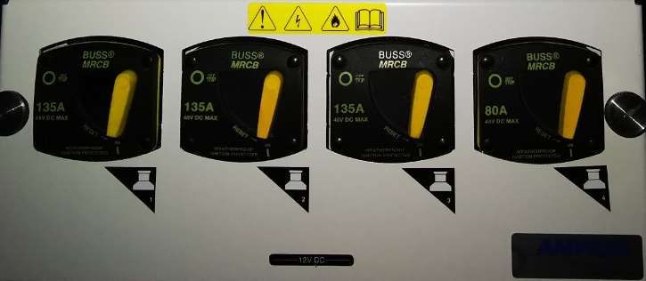
Inverter breaker behind stbd aft cabin door.

Mastervolt inverter in
starboard aft cabin.
4. Engine start procedure

You have two engines and therefore two start panels. You must switch on both engines to
manoeuvre the vessel.
• Make sure that the throttles are in neutral.
• Turn on the engine ignition by pressing the Power button on the panel.
• Press and hold the start button.
• Once the engines are running, check that you have cooling water coming out of the exhausts.
• To stop the engine, press and hold the stop button until the engine stops.
• Turn off the ignition panel by pressing and holding the Power button.

                                                  ENGINE START

                                                  ENGINE STOP

                                                  IGNITION ON/OFF

Should you have difficulty starting one of the engines then turn on the emergency parallel switch
in the port engine room. Remember to turn this off again after starting the engines.

                                                         Hold in to disengage
                                                         transmission
EMERGENCY PARALLEL STBD ENGINE COMP.
SWITCH PORT ENG COMP.
Should you hear an engine alarm during operation, check which light is on and
immediately shut down the engine - CALL HORIZONChecking Diesel Fuel
Tank Menu
Diesel Tank 1 Diesel Tank 2
Toggle through
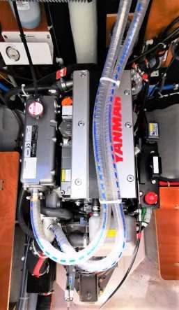
tank 1 and 25. Daily Engine Checks
The engines are in the transoms, one in each hull. It is important that you complete the
following checks on both engines.
• Check the oil level using the dip stick located on the right of the engine. The level should be
at least halfway between the empty and full marks. To add oil, open the orange oil filler cap
on the top of the engine.
• In front of the engine, mounted on the bulkhead, is the engine coolant reservoir (hidden from
view on the picture). The coolant level should be between the maximum and minimum lines.
• Check for any engine leaks or bilge water below engine.
• Check the belt for any damage and correct tension.
KEEP HANDS CLEAR OF ALL MOVING PARTS.
ENGINE WILL NOT START IF THE AUXILARY STOP IS IN THE OFF POSITION. ANY
PROBLEMS CALL HORIZON
COOLANT FILL
Raw Water Strainer
OIL FILL
Auxiliary stop
OIL DIP STICK BELOW
AUXILLARY STOP6. Generator
YOU MUST NOT RUN THE GENERATOR WHEN UNDERWAY.
Fly Again is fitted with its own Onan generator which will run the 110v outlets, the air
conditioning and will also charge the batteries instead of the engine.
Before starting the generator ensure the air conditioning units are off (Turn off all AC Units
before leaving the dock). The transfer switches are in the starboard forward cabin locker but
only need to be operated manually if there is a fault with the touch display at the nav station.
Call the manager on duty if there is a fault with the touch display.
Touch display at the helm stationUsing the touch display to start generator:
Home page Main Screen Return
Previous page
Next page
On/Off Button
Water and Battery Page
Fuel Gauges
Hit the return button while on the main page to the screen below and then the AC
Source menu to get to the next page.
AC Source menuHighlighted when Highlighted when
shore power is generator is running
connected
Inverter
110V Power Inverter voltage
supply
Air Conditioning circuit power
supply
Hit 110V power supply or Air Conditioning to get to the individual transfer switch.
Touch to switch to Switch off Touch to switch
shore power to generatorTo start generator, touch the
generator key on either side,
110V or Air conditioning to get
to the voltage/start menu.
Generator voltage and start
menu
Touch start
and the
generator will
automatically
prime and
startThree dashes flashing when
generator is starting.
Generator is running.
Generator
voltage/output.
Generator stop
button, touch and
the generator will
stop.
Once you have started the generator, gradually apply load by turning on the AC Units 5 minutes
apart. This is to avoid overloading the generator.Before hitting the stop button on the generator ensure all the air conditioning units
are off, let the generator run for 5 minutes (cool down).
GFCI switches are below
12-Volt panel. If there is
no power coming from
your outlets, ensure these
switches are in the on
position.
Resetting the generator
If the generator is running but the 110 sockets and Ac units are not powering up, reset
breaker to the left of generator control panel.
Cummins Onan Generator,
port bow locker
Generator Reset Breaker
DC Circuit Breakers, Emergency
Stop, Hour meter and
Start/Stop (Prime)Shore power/generator breakers
Behind Stbd Aft Cabin Door
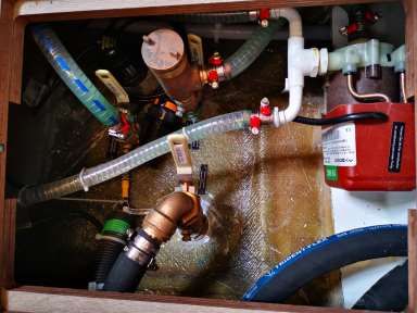
Generator/Shore Power Breakers Behind GeneratorGenerator raw water strainer:
Please do not run the generator when sargassum seaweed is present. The generator raw water
strainer is in the generator compartment to the right of the genset and can pick up seaweed and
other debris in the water. This can cause your generator to malfunction because of the lack of
water flow.
Cleaning the raw water strainer:
1. Before you clean the strainer ensure the raw water intake valve is closed.
2. Remove the housing cover, this can be done with a filter wrench.
3. Remove and clean the strainer.
4. Refit strainer.
5. Prime the strainer by pouring water into it until it overflows.
6. Refit housing cover.
7. Open the raw water intake valve.
8. Start the generator
9. Make sure water is coming out the exhaust.
If you still have a problem running the generator after cleaning the strainer, check for water in
the strainer. If there is no water in the strainer it means the raw water intake is blocked.
Clearing a blockage from the generator raw water intake:
1. Get the dinghy air pump.
2. Close the intake valve.
3. Remove cover and strainer from the housing.
4. Place the nozzle of the dinghy pump into the opening that is connected to the intake hose.
5. Open the intake valve.
6. Use the pressure of the dinghy pump to force the blockage out.
7. Once you have cleared the blockage, prime the strainer by pouring water into it until it
overflows.
8. Refit housing cover and start generator.
9. Make sure water is coming from the generator exhaust.
If you are unable to open the strainer, remove the intake hose where it is connected to the
strainer by undoing the hose clamps and use the dinghy pump to force out the blockage.
Please contact the manager on duty for further instructions.
Generator raw water strainer, STBD midship floorboard
Hand Tightened Cap7. Air conditioning Cabin Air conditioning The air conditioning units will operate when the vessel is plugged in to shore power or when the generator is running. Each cabin has its own individual air conditioning unit and there is a 5th unit located in the salon. The air conditioning units should be turned on after the generator has been running for 5 minutes (or once the boat is plugged into shore power) and the breakers should be shut off before stopping the generator or unplugging from shore power. Ensure the companionway and all hatches are closed; otherwise the compressors will freeze up. Starting the air conditioning: • Switch on the required units 5 minutes apart. • Each of these units also has an individual control which allows users to alter the settings for the individual units. Using the unit control panels: • Switch the remote units on using the ‘power’ button. • Set the temperature using the ‘temp’ arrow controls. • The units will work best if the minimum temperature is set no lower than 70 degrees. Set it below this and you risk frosting up the unit and causing it to shut down. • Only select the ‘cool’ mode. Press the mode button until the cool option is displayed on the unit. • The remote panel will automatically display the ambient temperature. • Control the fan strength using the ‘fan’ button. • Switch the units off by pressing the ‘power’ button. AC Breakers: AC Breakers are in the starboard aft cabin beside locker.
2    3 4 5                    6 78           9

                            1

                                                                                              10
                                                                                              11

                                         16        15        14       13       12

                                                                           Diagram Description of Control Display Panel and Indicators
1   Data Display - Large LCD readout displays current temperature,    9      Fan Speed Indicator - A row of five bars indicate the current fan
    set point, programmed values and error messages.                         speed, with more bars indicating a higher fan speed and fewer
                                                                             bars indicating a lower fan speed.

2   Set Point Indicator - Display shows SET when set point is being   10     Fan Mode Indicator - The word MANUAL displays when the fan
    adjusted. Normally display defaults to inside temperature.               is running in Manual Fan Mode. The word MANUAL does not
                                                                             display when the fan is running in Automatic Fan Mode.

3   Aux Heating Indicator and Aux Heat Mode Indicator (optional)      11     Dehumidify Mode Indicator - The word DEHUMIDIFY displays
    - A solid dot displays next to the words AUX HEAT when the               when you are in Dehumidification Mode. It flashes if optional
    electric heater is on and running in Aux Heat mode. The words            humidity sensor is connected and operating in the Cooling Mode.
    AUX HEAT display when you are in Aux Heat mode. (Press the               (Press the MODE button to select Dehumidification Mode.)
    MODE button to select the optional Aux Heat Mode.) See
    Programmable Function “23: Aux Heat Enabled/Disabled” on page
    12.
4   Heating Indicator - A solid dot displays next to the word HEAT    12     FAN Button - Press to select Manual or Automatic Fan Mode,
    when the compressor is on and running in Heat mode.                      indicated by the word MANUAL displaying or not displaying. In
                                                                             Manual Fan Mode, additional presses of the FAN button will adjust
                                                                             fan speed higher, then lower, then back to Automatic. In Automatic
                                                                             Fan Mode, fan speed is controlled by the microprocessor as a
                                                                             function of the difference between set point and inside
                                                                             temperature. See Programmable Function “4: Fan Response
                                                                             Differential” on page 9.

5   Cooling Indicator - A solid dot displays next to the word COOL    13     UP Button - Press to adjust set point up. In programming mode
    when the compressor is on and running in Cool mode.                      press to scroll through program modes and adjust values.

6   Cool Mode Indicator - The word COOL displays when you are in      14     DOWN Button - Press to adjust set point down. In programming
    Cool mode. (Press the MODE button to select Cool Mode.)                  mode press to scroll through program modes and adjust values.

7   Heat Mode Indicator - The word HEAT displays when you are in      15     MODE Button - Press to cycle through the modes of operation
    Heat mode. (Press the MODE button to select Heat Mode.)                  (refer to indicators). Mode sequence selections are COOL, HEAT,
                                                                             AUTO, AUX HEAT (optional), and DEHUMIDIFY.
8 AUTO Mode Indicator - A bracket and the word AUTO display to 16 POWER Button - Press to turn the system on and off. Note that
the right of the words COOL and HEAT when you are in Auto the Data Display remains on in the Off mode. You can continue to
Mode. If optional Aux Heat is enabled (see Programmable adjust set point, display temperature readings and activate the
Function “23: Aux Heat Enabled/Disabled” on page 12), a bracket manual fan to circulate air while the system is in the Off Mode.
and the word AUTO display to the right of the words COOL and
AUX HEAT. (Press the MODE button to select Auto Mode.)
Saloon AC Control
Touch to open main menu
Fan Speed
Temperature up and down
Main Menu
When Automatic mode is selected
the system provides both heating
and cooling, as required.
Only the cooling system operates.
Only the heating system operates.
This mode controls humidity during
periods when the vessel is
unoccupied and prevents the cabin
temperature from dropping below
the minimum default temperature
setting.
Air Conditioning ONAC troubleshooting:
Iced up unit: You can tell a unit is iced up when it is running but there is no air coming out of
the AC vent. You can also look at the actual unit, it will be covered in ice. Turn off unit and let
defrost. You can also move the mode from cooling to heat for about 5 to 10 mins until you feel
air coming out the vent again.
Unit not cooling: Check temperature settings. Ensure mode is set to cool.
HPF (Hight pressure fault): The AC units on the Fly Again are water cooled. A high-pressure
fault means that there is air in the system (lack of water flow). Check the sides of the vessel and
make sure water is coming out of the AC outlets on the hull. If there is no raw water flow the
unit will need bleeding.
Bleeding AC unit: Bleeding the unit means letting the air out the system until there is a steady
flow of water to cool unit. On Fly Again the unit is bled from the line connected to the AC pump.
First turn the unit on to restart the Air conditioning pump. Undo the hose clamps on the line
connected to the pump and remove it enough to let air and water out. Once there is a steady
flow of water refit the hose and retighten the hose clamps, check if water is coming out the side
of the vessel. The Ac strainer can also pick up seaweed and debris and might require cleaning at
times.
Speak to the manager on duty before attempting to bleed AC-Unit.
Ac pump under saloon floorboard
AC Intake and
Strainer
AC Pump, FWD
Cabin Floorboard8. Electronics:
B&G Triton² digital display and autopilot controller X2
B&G Triton² Autopilot control B&G Zeus³ 16 ChartplotterFusion Entertainment MS-RA70N Marine Entertainment System with Bluetooth
Volume rocker/Select Menu Source Skip track
Digital display
Power Play/Pause
Connecting your device via Bluetooth:
Hit the source button and select BT (Bluetooth).
Hit the Menu button and select discoverable.
Open Bluetooth settings on your device and scan for Bluetooth devices. The stereo should show
up in your list of devices as ‘Tola Sunrise’. An option should show up on your display asking to
pair with device and confirm pairing code, select ‘OK’. Once paired your song selection and
device name will show up on the stereos digital display.
Push to Volume rocker to adjust the volume in individual zones (Salon and Cockpit)9. VHF Procedures
Using the VHF radio:
Familiarize yourself with the method for switching channels, and with the squelch and volume
controls on your radio. Most radios have a button to instantly select Channel 16 – ensure you
understand how this operates or you could end up speaking on Ch. 16 when you think you are
on some other channel.
1. Make sure the radio is switched on, volume quite high, power to high unless the station you
are calling is very close.
2. Squelch up until loud hissing, and then back a little until the noise just stops.
3. Select the channel for calling (Channel 16, unless specified otherwise).
4. Press switch on microphone when speaking. Release immediately.
If no response, wait two minutes and repeat the call. If still no response, wait a further two
minutes before trying again. If calling on Channel 16, it is very important to switch to a working
channel after the contact is established. Do not use Channel 16 for your conversations – this
channel is for hailing and distress only.
Channels to use:
16 Hailing and Distress
74 Contact Horizon Yacht Charters (when in range)
12 Yacht Charter Companies working channel – assigned for yacht breakdown servicing and
emergency only
68 Marinas and Yacht Clubs – for lunch/dinner reservations etc
06 Ship to Ship – along with Channel 68 and 77 can be used for contact between boats
If your vessel is involved in a non-life-threatening incident with an object or with another vessel,
it is important that you contact the Horizon Office immediately at 494 8787 or 542 8788. Please
remember to get as much information as possible about your location, the other vessel’s
description and what damage has been done to your vessel so that we can best assist you.Failure to report any accidents or incidents in a timely manner may result in nullification of your hull damage insurance.
Types of emergency:
In the unlikely event that you are involved in an emergency stay calm and follow these steps.
You will also have an Emergency Procedure card next to your VHF.

Distress: “MAYDAY, MAYDAY, MAYDAY.”          This is an International Distress signal and an
imperative call for assistance. It is used only when a life or vessel is in grave and imminent
danger.

Mayday Relay: used to summon help for a vessel which is either too far offshore to contact the
coastguard directly, without radio capabilities or whose radio has been damaged or destroyed.

Urgency: “PAN-PAN, PAN-PAN, PAN-PAN” This is the International Urgency Signal and is used
when a vessel or person is in some jeopardy but is not considered to be in grave and imminent
danger.

Medical emergency: “PAN-PAN MEDICO, PAN-PAN MEDICO, PAN-PAN MEDICO” (Pronounced
med-ick-oh). This is an International Urgency Signal that should be used when medical advice is
needed.

Safety: “SECURITE, SECURITE, SECURITE” (Pronounced Say-cure-it-tay).          This is an
International Safety Signal and is a message about some aspect of navigational safety or a
weather warning.

How to issue an emergency message
Select Channel 16 and press transmit button on handset.

Say slowly and clearly ‘MAYDAY, MAYDAY, MAYDAY, CALLING ALL STATIONS.

This is…. (vessel name) ….’ and repeat vessel name 3 times.

Give position – vessel’s position in degrees of latitude and longitude or nautical miles from, and
bearing to, a navigational landmark.

Describe emergency – list the problem, the type of assistance needed; number of passengers
aboard (boat length, hull colour and type are also useful).

Wait 1 minute for a response, repeat message.

ALTERNATIVELY: Dial either 767 or 999 from any BVI cell phone or call 494- HELP
(4357).
 .
10. Batteries

  There are 3 ways to recharge your batteries.

  Engines:
  The batteries will need to be recharged as often as you deplete them. Conserving power will
  result in less time needed for charging, so turn off systems that you are not using. Your
  batteries will charge when the engines are running at 1400rpms or more, whether sitting at a
  mooring or motoring to a destination.

  •   Check the battery levels and make note of them before charging. If your batteries are close
      to 12.2 volts you should consider charging.
  •   Run the engines at 1400rpms or more for 1-1 1/2hrs twice daily
  •   Shut the motor off.
  •   Wait 5 minutes before checking the battery levels, (directly after turning off the motor they
      will remain in an excited state for about 10 minutes). After charging, your Domestic/House
      battery should rest on 12.8 volts.

  Shore power:
  Ensure that the battery charger breaker is selected on the 110v panel and that ‘Shore’ is
  selected rather than ‘Generator’ on the Selector switch.

  Generator:
  Ensure that the battery charger breaker is selected on the 110v panel and that ‘Generator’ is
  selected rather than ‘Shore’ on the Selector switch.

Touch to open battery
menu

                                     Port engine battery
Domestic/house Starboard engine
battery battery
Generator battery
Domestic/House
battery voltage
State of charge
Port engine battery
voltage
Starboard engine battery
voltageGenerator battery voltage
11. Anchoring & the windlass

Setting your anchor:

Preparation:
• Establish a nonverbal communication system between helmsperson and windlass operator, as
   with the noise of the engine and wind, verbal communication proves difficult.
• Shorten the painter so that it cannot go under the yacht and wrap around the prop.

Location:
• Choose a clear area to anchor in and you can see the bottom. A white bottom is sand and
   perfect for anchoring. A brown or green bottom will be grass, rock or coral. Only anchor in
   sand. Maximum depth would be 1/5th of your anchor rode. Remember the depth is set from
   the bottom of your keel so keel draft should be added to the reading of your depth gauge.
• Anchoring on a lee shore is not recommended and would recommend using both your
   primary and secondary anchor if you choose to anchor off a lee shore. (see below)

Action:
• Always have your engine revs increased to @ 1400 rpms before windlass operator touches
   the windlass remote. The windlass needs optimum energy to operate correctly.
• Minimum scope is 5:1. In heavy weather you may want to increase that, always ensuring
   your swing area is clear of any obstacles.
• Use the elements; approach from downwind or current, whichever prevails.
• Have the anchor ready to deploy. This may require you to slack the chain and manually push
   the anchor slightly overboard so that it will go deploy when you press down on the remote.
• Once the yacht is stationary use the electric windlass to drop the anchor to the sea floor. The
   elements will push you back and away from the anchor. Keep deploying chain until you have
   acquired the correct scope. Attach the snubbing line.
• Always attach the snubbing line before setting the anchor with the engine and whilst you are
   anchored. The snubbing line protects the windlass and it is important that you attach the
   snubber every time you set the anchor. Attach the hook around the chain link (the hook is
   too big to go through the link) and cleat off the bitter end of the line to a bow cleat. Pay out
   enough chain so that the snubbing line becomes taut.

•   If the hook falls of the chain, it means that there is not enough tension on the line. You may
    need to hold slight tension on the snubbing line as you deploy more chain until the snubber
    takes the load of the anchorage. Engage reverse, slowly building up to 1500 rpm to really
    drive your anchor into the sand. Take transits as you set the anchor so that you know that
    the anchor is not dragging.
• It is always advisable to snorkel the anchor and ensure it is bedded in correctly and not just
lying on its side or hooked on a rock.
Retrieving Primary Anchor:
• Never use the windlass to pull the yacht to the anchor. The windlass operator should point in
the direction of the anchor chain so that the helmsman can move slowly in that direction. As
soon as there is some slack on the anchor chain the bowman tells the helmsman to put the
engine in neutral and then increase RPMs. Bowman then retrieves all the slack chain. When
the chain becomes taut then you repeat the process from the beginning. Ensure the anchor
does not swing into the bow of the yacht.
Setting a secondary anchor:
• Your secondary anchor is a quick set type of anchor and is usually stored in the cockpit
locker. It has 30 feet of chain and about 170 feet of line. For this reason, we have always
found it easiest to put this chain in the dinghy with two people and deploy it from there. Take
note where your primary is and drive away from the yacht at a 45-degree angle of the
primary. Drop the anchor with the shank pointed at the yacht and deploy the rode as you
drive back to the bow of the yacht. Tie off at the bow. Once back on the yacht and dinghy
secured, manually take the slack out of the 2nd rode and tie off. Now engage reverse to 1500
RPMs as before.
Manual operation of the windlass
If you lose power to your windlass, start the engine and rev to 1500 rpms to make sure you
have not got low battery voltage. Check that the breaker shown below has not tripped in the
STBD cabin behind the door. If you still have no power, you can operate the windlass manually.
To drop the anchor, insert the windlass handle into the central hole on the top of the windlass.
Turn the handle anti-clockwise so that the gypsy loosens its grip on the chain. Your anchor is
now ready to drop.
Remove the safety line or safety pin, and push the anchor over the bow, keeping hands and feet
clear. Control the rate the chain pays out by tightening or loosening the wing nut with the
stainless handle.
When you have paid out enough chain, between 5 to 8 times the water depth, push the handle
forward to tighten the wing nut. Next, fit the bridle and release more chain on the gypsy so that
the load is taken up on the snubbing line.
To raise the anchor, put the handle in the outer hole and turn the whole drum clockwise, this will
wind in the chain. However, it is quicker if you pull the anchor up by hand as the helmsperson
motors forward a little at a time, to give you slack on the chain. If you are reasonably fit and
strong, it is possible to heave an anchor aboard.
Windlass BreakerELECTIC WINCH There is a two-speed electric winch at the helm station. Turn cap to expose the buttons or the cover the buttons to prevent accidental use of the winch. When using the electric winch keep an eye on the sail as it is going up to make sure battens don’t get caught in the lazy jack lines. Three two-speed winches at helm Two-way winch for travellers Winch Breakers The electric winch breakers will trip if a unit is overloaded. It is in the cupboard by the starboard companion way. To reset it simply push down the yellow lever to the ‘1’ position.
12. Picking up a mooring buoy

•   Ensure dinghy painter tied off short on the bow or amidships and clear of the prop.
•
•   Ensure there are 2 long dock lines at the bow, one attached to each bow cleat.

•   Approach mooring buoy, keeping the bow into the wind or current, whichever prevails.

•   Have a crew member on the bow to pick up the mooring pennant with the boat hook.

•   The bowman will direct the helmsman to the mooring, using the already established non-
    verbal communication system. Once at the mooring, inspect the buoy and pennant for any
    signs of wear and tear - generally the overnight moorings are well maintained, the day balls
    to a lesser degree. If you are ever unsure about a mooring buoy’s integrity, choose another
    location to moor up.

•   Pick up the mooring pennant using the boat hook. Pass one dock line through the pennant
    and fasten the dock line back on its cleat. Repeat with the second line.

•   Once you have secured your lines remember to centralize the wheel and lock in place to
    avoid the yacht sailing around the buoy.

•   Now set up a back-up line. The line should lead from a bow cleat to the mooring buoy and
    fasten on to the buoy itself. It is always easier to do this from the dinghy.

•   To depart, slowly motor the yacht forward to create slack, release one end of the dock lines
    from their cleats and allow to slip through the pennant eye. Allow the pennant to fall into the
    water. Fall back with the wind or current and be careful not to foul your prop on any
    moorings.

•   Remember to tie your dinghy on a short painter and away from the stern whenever
    you are manoeuvring in close quarters
13. Bilge Pumps
Your yacht is equipped with two manual and two electric bilge pumps (one in each hull). The
primary bilge pumps are on float switches and operate automatically providing that the bilge
pump switch on the 12v panel is left in the center position. If the float switch fails, the pumps
can be forced to operate by pushing the switch located on the 12v panel. It is important that you
check all the bilges once a day.
The engine compartments drain into the main bilges.
The manual pumps are located either side of the cockpit at the rear and the handles for these
are towed under the central cockpit locker lid.
MANUAL BILGE PUMP14. Freshwater system
Fly Again is equipped with two inter-connected water tanks with a combined capacity of 160
gallons. There are therefore no changeover valves.
Before filling the tanks let the water run from the hose for a while before placing the end into
the filler located amidships on the bow, just in front of the salon windows. Please ensure that the
correct filler is used, NOT the waste tanks or the diesel fills.
To use the freshwater system, turn on the freshwater breaker on the 12v panel and open a
faucet. When the tanks run out of water the pump will run at high speed and the faucet will
start to cough air. As soon as you hear the pump running continuously, check to see if anyone
is using water. If not, switch off the pump immediately to prevent the pump from drawing more
air into the system or the pump overheating. The water level can be read by pressing the top
button under the LCD display on the 12v panel.
Water & Fuel Gauges
Touch to open
water gauge
Water gauge15. Watermaker
Fly again is fitted with a Sea Recovery Ultra Whisper III Watermaker.
Start/Stop button
1. Powers on and sets the system in its initial state.
2. When the system is producing water and the START/STOP button is pushed, the
system stops all pumps and diverts water into the sea.
3. Resets all faults.
Note that this button performs its designated action, regardless of whether you are
browsing a menu.
Fresh flush
This button initiates the Fresh
Water Flush (FWF) cycle.
Cycle button
This button allows the operator to cycle Booster Pump button
through the process and configuration Start the booster pump. Press the
parameters. Start/Stop button to stop operation. Note
• Press the CYCLE button once to view that this button starts the booster pump,
to view the Display Menu. regardless of whether you are browsing a
• Press and hold CYCLE for 5 seconds menu.
to view the Configuration Menu.Start Production
System on LED
Portable Water Watermaker is running. LED
Salinity of the product flashing when water
water has diminished unpotable water is being
to factory setting diverted overboard and solid
when diverted to tank
Power LED
When
Watermaker is on
and receiving
power from shore
or generator
Stop
Start
Production
Production
Needs Service
Filters might need
replacing
To start the system, press the “START” button on the panel just below the nav desk. If the
system automatically shuts off immediately or after 20 seconds of operation, this may be due to
a system fault. Look at the display on the unit to confirm whether a fault has occurred. If there
is a fault, make note of the fault code and contact the manager on duty.
If there are no unforeseen abnormalities, the Ultra Whisper System pressure will automatically
increase to normal operating range immediately after starting.
If any abnormality develops, stop the system and correct the problem.
Although the system is producing “product water,” the “product water” may not be “potable” for
up to 30 minutes. The Operating/System On light will blink, when product water is unpotable
and becomes solid “green”, when the product water is potable. The display on the unit should
say “Diverting to sea”.
The salinity of the product water diminishes gradually and is measured by the salinity probe.
When the salinity of the product water has diminished to the factory setting, the salinity
controller will energize the operating light becomes solid “green” and the 3-Way Product WaterDiversion Valve opens to product. At that instant, product water will be routed to the charcoal
filter, pH neutralizer, UV sterilizer and onward to the potable water storage tank (depending on
your options).
Stop Production
Stop the system by pressing the “START/STOP” button once.
The freshwater flush lamp will illuminate, intermittently blinking for 2 minutes. This time delay is
to allow the R.O. BOOST to dissipate its pressure. After the 2-minute wait period, the freshwater
flush automatic cycle will begin, as indicated by a steady, non-blinking illumination of the
freshwater flush lamp.
After the freshwater flush cycle is complete, the freshwater flush lamp will illuminate and
intermittently blink in the stand-by mode. Every 7 days, the freshwater flush rinse cycle will
repeat automatically.
If the “START/STOP” button is pressed twice, the automatic freshwater flush cycle will be
cancelled, and the freshwater flush lamp will not be illuminated.
If the freshwater flush is activated, do not interrupt power. If the power source has been turned
off, the freshwater flush will not cycle every 7 days.
25 Micron Prefilter and 5 Micron Prefilter.
Just behind the port engine.
Watermaker intake and StrainerWatermaker troubleshooting Error ID 1: High Salinity Fault The Product Water salinity is above 100ppm for more than 10 consecutive seconds. 1. We recommend using a portable TDS meter to determine if the problem is with the RO Membrane Element or with the Salinity Probe and Electronic monitoring system. 2. A damaged or worn Product Water O-ring at one of the End Plugs within the High-Pressure Vessel is allowing Feed Water to mix with Product Water, which would typically result in higher than normal Product Water Flow. However, a small nick in the O-ring may allow enough Feed Water to mix with the Product Water to cause the condition without resulting in a noticeable increase in Product Water Flow. 3. A crack in one of the End Plugs within the High-Pressure Vessel is allowing Feed Water to mix with Product Water, which would typically result in higher than normal Product Water Flow. However, a small crack may allow enough Feed Water to mix with the Product Water to cause the condition without resulting in a noticeable increase in Product Water Flow. 4. RO Membrane Element is fouled due to normal use and requires cleaning. 5. Salinity Probe has debris on the probe causing the system to read poor water quality. Clean the Salinity Probe with a toothbrush. Error ID 2: High Pressure Fault If the High-Pressure Sensor increases beyond 950 PSI and the System shuts down, press the "Start/Stop" button. A high-pressure fault can be caused by: • Low Temperature Feed Water • High Salinity Feed Water • Fouled RO Membrane Element • Blockage in the Brine Discharge Line • Blockage in the Product Water Line Error ID 3: Low Pressure Fault A low-pressure fault can occur when the following conditions occur: • The value at the Low-Pressure Sensor is below 4 PSI for more than 20 seconds • The Low-Pressure Sensor is disconnected or malfunctioning • The value at the High-Pressure sensor is below 4 PSI for more than 20 seconds • The High-Pressure Sensor is disconnected or malfunctioning. To troubleshoot, check for the following: • Cock Valve must be fully open • Air suction leaks at all components and fittings prior to the Feed Pump • Whether or not the Sea Strainer Mesh Screen is clean (no manufacturing or installation debris) and if air suction leaks are present • Whether or not the Pre-Filter Element is clean (no manufacturing or installation debris) • Whether or not the Plankton Filter Element is clean (no manufacturing or installation debris) 60 • No kinks, blockages or air suction leaks in the inlet line • The Feed Pump is operational and delivering flow and pressure • Whether or not the Inlet Thru-Hull Fitting is clean (no manufacturing or installation debris) and if air suction leaks are present • Caulking compound within the opening
• Shipping cover or tape below the hull in the water
• Casting slag on the “fingers” below the hull in the water or within the orifice
• Plastic bag or other debris in the water below the hull in the water

Error ID 4: Low Voltage Fault
Check system voltage inside the Control Panel. The system must receive adequate voltage at
start up and during operation for normal operation. DC systems will shut down by design when
the voltage falls below:
• 12 VDC Systems: 10.5 VDC
• 24 VDC Systems: 21.5 VDC Loud or Whining Pump Loud or whining pump is common after
long use. The cause of the loud noise is a drop motor rpms or cavitation. If the pump is
cavitating, check for clogs, kinks, or dirty sea-strainer. If the noise persists, check motor supply
voltage at the system source and at the motor. If there is not enough supply voltage, it will
cause the motor to run at a lower rpm.

                  Watermaker Breaker behind stbd aft cabin door
16. Heads
• Nothing is to be put down the head unless it has been digested first.
• Fly Again is fitted with electric heads.
Blocked heads due to any other blockage other than mechanical failure of parts is at
the charterer’s expense as per your charter contract. This includes the chase boat and
technicians fee.
Flush/ Rinse
Bowl
Wet Bowl
(Left) Dry
Bowl (Right)
• Before use, ensure that there is enough water in the bowl.
• If the bowl is empty, hold the lower Flush Control Switch on Wet Bowl position until
the flushing pump is primed, and water enters the bowl.
• During use, pump as necessary to keep the contents of the bowl low enough for comfort.
• After use, hold the upper Flush Control Switch Flush/Rinse bowl until the water in
the bowl is clear (Flush for as long as possible so the waste travels all the way through
the lines.
• When the water in the bowl is clear, hold the lower Flush Control Switch on the Dry Bowl
side until the bowl is empty. Always leave the bowl empty to minimize odour and
spillage.
AFTER USE DRY BOWL (SHUT) ( ) THE FLUSH CONTROL.Fly Again has an operational holding tank for each hull. Waste goes directly to
the holding tank and can only be discharged by holding the down the button
above the holding tank gauge. Always remember to flush your holding thanks
when sailing or motoring since on Fly Again the holding tanks are always
accumulating waste and must be flushed manually.
Check that the holding tanks are empty before returning the vessel and please
flush each one through to minimize residual odors.
Hold to discharge holding tank
Holding tank gauge17. Showers
Your yacht has a hot & cold, fresh-water shower in each head and on each of the transoms. If
the engine has been running, the hot water can be very hot – be cautious! Hot water is
generated automatically through running the main engines. Hot water can also be created by
turning on the water heater breaker on the 110v panel with the generator running or on shore
power.
To use the showers, the fresh-water pump must be activated on the 12v panel.
The waste shower water can be
drained by pressing the black
button on the shower wall.
Deck Shower
The valve next to the shower head will switch the water on and off and control the temperature.
To use the shower head, simply pull it out and press the lever on the back. If no water comes
out, make sure that the 12V water switch is on and the shower hose is not kinked.18. Propane and stove
The propane tank locker is in the cockpit beneath the fwd locker. There are two propane tanks,
one connected to the supply and one spare.
To use:
• Turn on the Propane switch in locker below the galley sink. This opens the solenoid on the
tank.
• To light, turn the knob that corresponds to the burner that you wish to use through 90
degrees anticlockwise, push the knob in and light the burner using the matches provided.
• Hold the knob in for 10-15 seconds, then release. Make sure that the flame goes all the way
around. Reduce any wind that may hinder this by closing hatches or switching off fans.
• Light the oven in the same way, pressing the knob in whilst holding your match to the
bottom burner.
• If you cannot get it to light, check the manual valve on the propane tank itself.
The 12v solenoid system is USCG approved device. You do not need to shut any manual valves
unless you wish.
THREE BURNER STOVE OVENGas safety
All our yachts are fitted with propane detectors. On Fly Again, the display is located to the right
of the 12V panel. The propane ‘sniffer’ has been placed in the bilge (propane is heavier than air
and so will sink into the bilge). The detectors are sensitive to several types of gas and will
trigger the alarm. The alarm can also be triggered if there is moisture in the bilge. If the alarm
sounds it does not necessarily mean that the propane system is leaking, so don’t panic!!
Ifthe alarm goes off, follow these steps:
• Close the valve on the propane tank.
• Check the stove and surrounding area for propane smell.
• If detected, open all the bilges and hatches. Point the boat downwind and use the manual
bilge pump to pump out the bilges.
• Call Horizon immediately
Propane detector switch behind
starboard aft cabin door
Under no circumstances should you use the electrical bilge pumps or any other
electrical system if you suspect a gas leak. Call Horizon immediately.19. Refrigeration
There are two 12-volt refrigerators and a 12-volt freezer on board your vessel. This system is
designed to run 24hrs a day if you wish. To ensure that it does not fail there are two things you
should do.
• Firstly, keep your batteries charged. If the level goes below 12v the system will malfunction.
Refer to section 10 for charging instructions.
• Secondly, do not puncture the cold plate in your fridge! Do not chip at the ice or use any
other sharp items in the fridge. If something is frozen to the side of the fridge do not force it
away. Poor warm water on it if you need to melt the ice.
Each unit can be individually controlled using the thermostats located in each unit. On your
arrival, the dials will all be set to their coolest setting. Keep it on this setting until all your food
has chilled thoroughly. Then you can turn the system down or off if you wish. Or if it is not cold
enough you can augment the system with ice.
Ask one of our staff for a deck cooler if you would like one for storing your drinks. It will keep
the drinks cooler and the refrigeration colder, as people will not be going in it every 5 minutes
for a drink. There is also an in-build cooler for drinks just forward of the salon seating.
Please note that we are in the tropics and we cannot guarantee that items will remain frozen
when placed in the fridge and that fruit, vegetables and other fresh produce may have a
shortened shelf life.
Ice maker Cockpit Fridge Galley Fridge Freezer20. BBQ • When using the BBQ, tie your dinghy off at the side of the yacht, not off the stern. • Never use the BBQ while sailing. • Never use the BBQ on a dock. • Never change propane tanks when using the BBQ. • Make sure someone is always tending the BBQ when hot. • Call us if you have too much food.
21. Fire Safety

Fire extinguishers are installed in each cabin, under the salon seating and in the central cockpit
locker.

Prevention is the best answer to fire safety.
• Always switch off the safety solenoid when stove is not in use
• Never leave the stove or oven burning unattended.
• Never change propane tanks whilst barbequing.
• Never smoke below decks.
• Never smoke when changing propane tanks.
• Safely store any flammable liquids (for example charcoal lighter fuel).
• Keep matches away from children.

Engine compartment fire:
In the event of a fire in the engine compartment use
the fire extinguisher positioned closest and discharge it
through the access hole located centrally on each aft
cabin headboard. There is a fully automatic fire
extinguisher in each engine compartment.
• Pull the yellow key out.
• Press down on the red button until all the contents
   of the extinguisher have been discharged.
• Fuel shut-off valves are under each aft bunk.
• Do not open the engine compartment even if you
   think the fire has been extinguished, dying embers
   can easily be re-ignited by a fresh supply of oxygen
   (air).
                                                            Fuel shut off valves
                                                            under aft cabin
 Engine Fire Access Hole
                                                            bunks
Open fire:
• Pull out the yellow safety tab.
• Point the extinguisher at the base of the fire and press down on
the red button to discharge contents.
• Generously cover the base of the fire and surrounding area to
ensure the fire is under control and cannot spread. Continue
discharging extinguisher until the fire is out.
Galley fire:
• Shut off the propane at the tank.
• Take the fire blanket out of its container.
• Carefully lay the blanket over the fire, laying the blanket away from
you and keeping yourself always protected from the flames.
• Ensure hands and limbs are protected from the fire by the blanket.
• Once in place leave the blanket until all heat has gone from the
scene of the fire, this way you can be sure that the fire has gone out
and will not re-ignite.
Smoke alarm:
• There is a battery-operated smoke alarm mounted in the salon. This
alarm will be triggered by smoke caused by cooking or burnt toast.
Opening a hatch to allow ventilation will minimize triggering the alarm.
For safety purposes, the 9v battery should not be removed from the
smoke alarm.22. Dinghy & Outboard
The driver of the dinghy must be over 18 and must always be wearing the kill cord.
Never operate the dinghy under the influence of alcohol or drugs.
• Always tow your dinghy on a short line while motoring and a long line while sailing, always
tow with the engine leg up as it gives you an extra half knot.
• If conditions are very rough, the outboard needs to be mounted on the push-pit.
• When going ashore for an evenings entertainment allocate a dinghy captain, someone who will
bring the whole crew back to the boat safely, allowing the rest of the crew to enjoy various
local cocktails and concoctions.
• To start the engine, lower the motor into the water using the lever on the starboard side of the
engine. The lever position corresponds to the motor position, up and fwd for towing and back
and down for driving. Check you are in neutral and the safety cord is in place. For starting
an engine that has been at rest for 3 or more hrs use the choke. Pull the choke out and set a
few revs with the throttle. Do not twist the throttle trying to prime the engine. You will only
flood it. Face the engine and pull the start cord and push the choke back in as soon as it runs.
If it runs for a second but cuts out, try again without the choke.
• To stop the engine, press the button on top of the kill cord, or pull the kill cord out.
• Keep the kill cord with you to prevent anyone from borrowing it. You have been provided a
dinghy lock and cable. Use them.
• Do not drag the dinghy onto a beach; anchor it off or put it on a dock with a stern anchor to
prevent damage from going under or hitting the dock.
• Do not speed in and around other yachts, speeding fines have been introduced.
• At night, an all-round white light must be displayed along with red & green side lights, and it is
always a good idea to have a flashlight with you, to show the way, and warn other vessels of
your presence.
• Wear the life preservers provided in the cockpit lockers when in the dinghy.
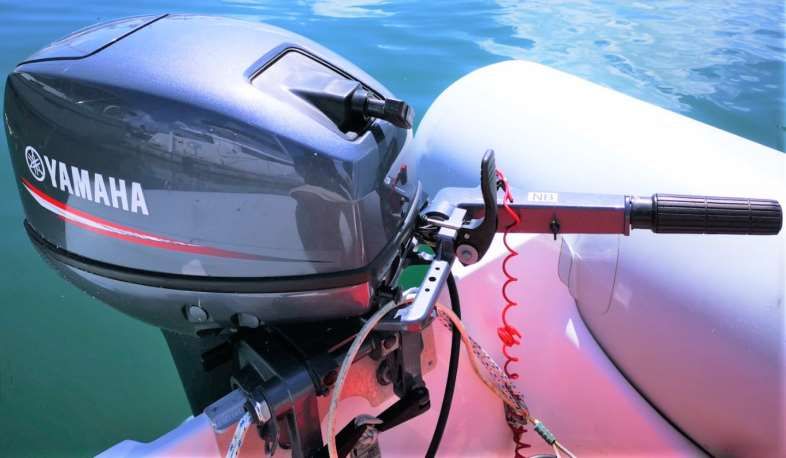
• GAS to OIL ratio, 1 gallon: 3 ounces.Outboard start procedure:
1. Place Kill cord under kill switch (Dinghy driver must always wear the kill cord).
2. Open vent on fuel tank cap (this vent can stay open; it allows air out but will not allow
water to go in). The fuel in the tank expands in this climate and if vent is left
closed it can damage the tank and cause a fuel leak.
3. Few pumps on fuel line bulb.
4. Make sure outboard is in neutral.
5. Add some revs using throttle on tiller handle.
6. Pull on start pull cord.
7. If the outboard does not start then pull choke and try again, as soon as the outboard start
push choke back in.
Outboard
Pull cord
Gear shift Throttle and tiller
arm
Kill cord and kill switch
Choke
Tilt lever
Fuel tank
Vent on fuel cap24. Dinghy lift Lowering the Dinghy Lift: • Refit the dinghy plug if it was removed. • Undo the safety locks on both sides (port and starboard. • Holding down the switch until the platform just over the water. • Undo the dinghy safety straps. • With the dinghy painter in hand continue lowering the dinghy until it is afloat. • Once the dinghy is off the platform, lift platform out of the water. Raising the Dinghy Lift: • Move dinghy over the lift platform. • Raise platform until dinghy is resting on the two holsters. • Secure dinghy safety straps. • Raise platform all the way up. • Refit and secure safety locks on both sides. Dinghy Lift Control Switch Dinghy Lift Breaker
You can also read