Specification for Road Safety Hardware Systems - APPENDIX C: TEMPORARY ROAD SAFETY HARDWARE SYSTEMS - NZ Transport Agency
←
→
Page content transcription
If your browser does not render page correctly, please read the page content below
Specification for Road Safety
Hardware Systems
APPENDIX C: TEMPORARY ROAD SAFETY HARDWARE SYSTEMS

                                                 8 April 2019
NZTA M23C 2019
INTRODUCTION AND REFERENCES
This hardware summary manual has been prepared to assist
organisations and individuals who interact with Temporary
Road Safety Hardware Systems. The technical details
within this manual have been extracted from the respective
product, installation and technical manuals of each device.
Wellington 6141
For more detailed information, refer to the individual manuals
for each product or contact the System Owner/Supplier.
The information, commentary and details provided in this manual
are collected from a variety of reliable sources however the
System Owner/Supplier formally issued and endorsed material
must still be used as reference material for products. Do not
utilise a device listed in this manual without first consulting the
System Owner/Supplier and obtaining the correct and most
recent documentation for the product.
This manual was prepared by Parallaxx Ltd for the NZ Transport
Agency with the intention of providing basic outline detail on all
accepted temporary road safety hardware systems for use by NZ
Transport Agency.
DOCUMENT REFERENCES
AS/NZS 3845 Part 1:2015
AS/NZS 3845 Part 2:2017
CoPTTM (Section B12, Temporary road safety barriers)
CoPTTM (Section C, road safety barrier systems)
NZTA M23
AUSTROADS Part 6: Roadside Design, Safety & Barriers
AUSTROADS Part 3: Geometric Design
AMERICAN ASSOCIATION OF HIGHWAY AND TRANSPORTATION OFFICIALS (AASHTO) Manual for Assessing Safety Hardware
(MASH)
The NZTA is part of, and contributes to, the Safer Journeys programme.
Safer Journeys is the government’s strategy to guide improvements in road safety over the period 2010–2020. The strategy’s vision is a safe
road system increasingly free of death and serious injury. It is a coordinated effort across partner agencies to improve each aspect of road
safety – better behaviors, a safer road environment, safer speeds and higher vehicle standards.
For more information visit www.transport.govt.nz/saferjourneys
NZTA M23C 2019

CONTENTS

GLOSSARY .........................................................................................................................................1
WATER-FILLED BARRIER SYSTEMS (including End Treatment)..................................................... 3
Armorzone ................................................................................................................................................. 3
Ricochet ..................................................................................................................................................... 5
Sentry ......................................................................................................................................................... 7
TrafFix Water Cable Mash TL2 Barrier + Sled Mini End Treatment .............................................................. 9
Water-Wall TL1 ................................................................................................................................................ 11
STEEL BARRIER SYSTEMS (excluding End Treatment) ....................................................................13
BarrierGuard 800 ............................................................................................................................................ 13
Defender 70 ........................................................................................................................................................... 15
Defender 100 (FS, HC & LDS variants) ..................................................................................................... 17
ZoneGuard ...................................................................................................................................................... 19
CONCRETE BARRIER SYSTEMS (Excluding End Treatment) ............................................................21
Delta Bloc DB80 K150S ............................................................................................................................ 21
JJ-Hooks .................................................................................................................................................... 23
TCB-1 ...................................................................................................................................................................... 25
END TREATMENTS ......................................................................................................................... 27
ABSORB 350 ............................................................................................................................................. 27
ACZ-350 ........................................................................................................................................ 29
SLED-Euro ....................................................................................................................................................... 31
SLED-US .................................................................................................................................................... 33
QuadGuard ............................................................................................................................................... 35
SCI-100 ..................................................................................................................................................... 37
TAU-II ....................................................................................................................................................... 39
TRACC .................................................................................................................................................41
X-TENuator.......................................................................................................................................... 43
TRUCK MOUNTED and TRAILER ATTENUATORS.......................................................................... 45
Alpha 70K (NCHRP350) ..................................................................................................................45
Scorpion I (NCHRP350 Model A, C & C-90) ................................................................................... 47
Scorpion II (MASH Model A, C & C-90) ........................................................................................... 49
Scorpion II Trailer Attenuator (MASH) .......................................................................................................... 51
Stuer-Egghe JL-D-850 ‘Julietta’ 100K (NCHRP350) ........................................................................ 53
U-MAD (NCHRP30 70K and 100K Models) .............................................................................................. 55
Verdegro Blade (MASH) ........................................................................................................................... 57
NZTA M23C 2019 | 1

GLOSSARY

Anchorage                    A barrier system may be anchored to the ground to limit deflection.

Bi-directional application   Two-way traffic. E.g. Barrier hardware that can be hit by both adjacent and opposing traffic.

Chevron                      Retro-reflective chevron signs attached to the barrier units to guide drivers along a temporary barrier
                             system (refer CoPTTM B12).

Clear Area                   A clear area is the area adjacent to the traffic lane that should be kept free from hazards that could be
                             impacted by errant vehicles.

CoPTTM                       NZTA Code of Practice for Temporary Traffic Management.

Crashworthy                  A feature that has been proven acceptable for use under specified conditions either through crash testing
                             or in-service performance.

Crossfall                    The transverse sloping of the road surface toward the shoulder or gutter.

Deflection                   The horizontal displacement of the barrier when impacted.

End Terminal                 A crashworthy end treatment must be provided when the end of a barrier is exposed to head-on impacts.

Energy Absorbing Unit        The individual units in a crash cushion that absorb impact energy.

FHWA                         USA Federal Highways Administration.

Flare Rate                   The curvature applied near the end of a road safety barrier installation. Expressed as the ratio of the
                             longitudinal distance to the transverse offset, by which a road safety barrier flares away from the road.

Flexible Barrier             Barrier systems which dissipate crash impact energy largely by deflection of the barrier system. Lower
                             impact forces are imposed on the vehicle and occupants.

F-Shape Barrier              Concrete barrier of the current accepted F-shape cross-section.

Gating                       A road safety barrier terminal designed to allow an impacting vehicle to pass through the device, when
                             impacted at an angle, upstream from the point of redirection.

Impact angle                 For a longitudinal barrier, it is the angle between the face of the barrier and the vehicle’s impact direction.

Length of need               The required length of barrier system that is re-directive, to shield the hazard.

MASH                         Manual for Assessing Safety Hardware (MASH) is the current protocol for crash testing of road safety
                             hardware and devices. Current version is the 2016 publication

NCHRP-350                    National Co-operative Highway Research Program (report) 350. Superseded by MASH 2016

New Jersey Barrier           Generally, a concrete barrier of the New Jersey Barrier profile. Superseded by the F-shape.

Pinning                      Either connecting adjacent transportable barrier sections or fastening barrier sections to the pavement
                             of ground.

Point of Redirection         That point on a barrier system downstream of which will be redirective. Previously referred to as “point of need”

Proprietary                  A road safety barrier system that is the subject of patent or other intellectual property rights.

Redirective                  The ability of a barrier system to re-direct an impacting vehicle without barrier pocketing or rupture.

Ribbon Strength              The longitudinal strength of a barrier system to provide crash energy containment and redirection.

Rigid Barrier                Barrier system that has no deflection under impact. Higher impact energy transmitted to vehicle
                             and occupants.

Semi-Rigid Barrier           Barrier system deflects during re-direction. Impact energy to vehicle and occupants is less than for a rigid
                             system but greater than a flexible system.

Shy Line                     The distance from the edge of the travelled way outside of which the start of a roadside object (e.g.
                             barrier) will not cause a driver to change their vehicles lateral placement or speed.

Sight/ Anti-Gawk Screens     Screens to shield visual distractions from passing drivers.

Slope                        The relative steepness of the terrain expressed as a ratio or percentage.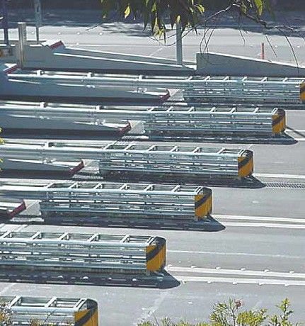
NZTA M23C 2019 | 2

Test Level (TL)               A set of prescribed test conditions, defined in terms of vehicular mass, impact speed and angle that
                              defines the crash energy.

Uni-directional application   One-way traffic, e.g. relating to road safety hardware that cannot be hit by opposing traffic.

Vaulting                      Abrupt upward movement of an impacting vehicle.

Wear and tear                 Damage that naturally and inevitably occurs as a result of normal in-service use or aging.
NZTA M23C 2019 | 3
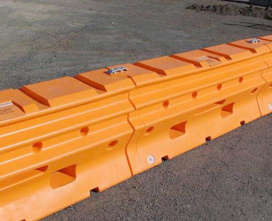
WATER-FILLED BARRIER SYSTEMS (including End Treatment)
ARMORZONE TL2 PLASTIC BARRIER + AMORZONE END TREATMENT
SUMMARY
SUPPLIER: Ingal Civil Products http://(www.ingalcivil.co.nz)
TEST LEVEL / CONDITIONS: NCHRP350 TL2
PRODUCT MANUAL click for product manual download
ArmorZone TL-2 Plastic Barrier a 100% polyethylene water filled barrier (no steel reinforcement) to have been judged to have satisfied the
evaluation criteria of NCHRP 350 Test Level 2 (TL-2). The polyethylene composition, profile design and steel pin connector allow the barrier to be
installed straight or curved.
ArmorZone TL-2 Plastic Barrier made up of plastic units that are joined together using a steel pin connector and filled with water. This provides a
positive work zone barrier protection to temporary construction sites and other miscellaneous roadside activities.
The ArmorZone End Treatment is a free standing ‘special’ end unit that can be fitted to the barrier in a tangent position if required. If this end
treatment is not used the barrier will need to be flared.
In-service impact deflection in excess of the test values indicated below must be allowed for in any temporary traffic management plan utilising the
ArmorZone TL-2 Plastic Barrier System. All relevant minimum requirements of CoPTTM in regard to working spaces and safety zones must be met
irrespective of the variant in use, in particular the test level of the system must meet or exceed the test level required for the operating speed of
the adjacent traffic (refer CoPTTM B12.1).
TECHNICAL INFORMATION
DIMENSIONS 2m length unit
450mm width (base)
WEIGHT 50kg (empty), 550kg (filled)
MINIMUM LENGTH 50m
(2 End Treatments and 23 units)
LENGTH OF NEED 16m (8 units)
MINIMUM RADIUS 28m
CLEAR AREA 2.1m behind the barrier
6m x 22.5m clear area for the end treatment to enable the system to gate if hit downstream from the head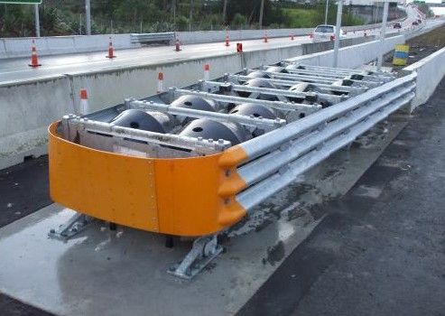
NZTA M23C 2019 | 4
GRADE OR PLACEMENT A maximum approach and cross slope of 1V:10H is preferable. On slopes greater than this
RESTRICTIONS approval is required from the road controlling authority.
Do not install in front, behind or on a curb. Approval is required from the road controlling
authority otherwise.
DEFLECTION 2.1m from rear edge of barrier (70 km/h, 2000kg vehicle, 25° angle)
WATER FILL HOLE DIAMETER 125mm
WATER FILL CAPACITY 520 litres
OTHER RESTRICTIONS / All units must be connected with the appropriate steel connecting pin and filled with water
CONSIDERATIONS when in use.
The adjacent road operating speed must be limited to 70 km/h and the installation should
endeavour to minimise the impact angles to 25° (1 lateral: 2.14 forward).
The ArmorZone TL2 End Treatment forms an integral part of this system and MUST be
installed and maintained in accordance with the product installation/maintenance manual and
relevant NZ Transport Agency specifications.
Should the end treatment component of this system NOT be fitted, the barrier system will be
considered non-conformant with the Interim Acceptance notice.
Site specific grading may be necessary to ensure that there are no “humps” or “hollows” that may
significantly alter the impacting vehicles stability or substantially alter the barrier height in
relation to the ground.
• ArmorZone is a stand-alone barrier and does not require at any stage during installation that the surrounding soil be dug or drilled
in anyway.
• ArmorZone barrier can be used in both “roadside’ and ‘median’ applications.
• It is recommended ArmorZone systems be installed on a compacted surface.
• There are no tools required to install the components of ArmorZone. The units can be manually lifted and positioned by two personnel
• Ensure that sufficient width and traffic control is available before installing ArmorZone.
• Depending on location, delineation may be required as per the Road Controlling Authority guidelines.
NOTES: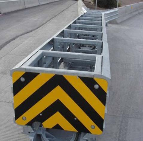
NZTA M23C 2019 | 5
RICOCHET TL2 PLASTIC BARRIER SYSTEM + RICOCHET TL2 END TREATMENT
SUMMARY
SUPPLIER: Advantage Plastics (http://www.advantageplastics.co.nz)
TEST LEVEL / CONDITIONS: MASH TL2
PRODUCT MANUAL click for product manual download
The Ricochet TL2 Safety Barrier and Terminal End is a rotational molded product manufactured from LHDPE (Linear High Density Polyethylene)
polymer.
These Barriers can be connected together by using the Ricochet galvanized pin to form a longitudinal straight or curved line for protection and
traffic flow direction for all road and construction sites and situations. Barriers are designed to be filled with water in accordance with the TL2
MASH standard they are certified for.
The Ricochet Terminal End and Terminal End Cap are designed to connect directly to the Ricochet Safety Barrier to form ‘Terminal Ends’ at each
installed length of barrier which results in the certified ‘system’.
In-service impact deflection in excess of the test values indicated below must be allowed for in any temporary traffic management plan utilising the
Ricochet TL2 Safety Barrier System. All relevant minimum requirements of CoPTTM in regard to working spaces and safety zones must be met
irrespective of the variant in use, in particular the test level of the system must meet or exceed the test level required for the operating speed of
the adjacent traffic (refer CoPTTM B12.1).
TECHNICAL INFORMATION
DIMENSIONS 2000mm length (pin to pin length is 1700mm when inter-connected)
580mm width, 1020mm height
WEIGHT Barrier: 62kg (empty), 620kg (full)
Terminal end: 42kg
MINIMUM LENGTH 61m
(2 x end treatments (each 2 yellow sections + end cap) and 32 x orange barrier sections)
CLEAR AREA 6m x 22.5m clear area to enable the system to gate if hit downstream from the head
GRADE OR PLACEMENT Ground conditions must be of satisfactory compactness and levelness does not exceed 10%
RESTRICTIONS (1 vertical, 10 horizontal) for both longitudinal and cross slope.
Must not be installed on top of or in front of any curbs or channels
WATER FILL CAPACITY 600 litres for each barrier
DEFLECTION 2.27m (50 km/h, 2270kg pick-up, 25° angle)
3.50m (70 km/h, 2270kg pick-up, 25° angle)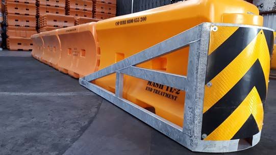
NZTA M23C 2019 | 6
OTHER RESTRICTIONS / Terminal End units and Terminal End Barrier Caps (Yellow) must not contain water as they are
CONSIDERATIONS certified not to.
When assembling the Barrier System always have a clear working zone of at least 2 metres on
either side of the barrier
Lifting Barriers must be by mechanical methods and use the lifting provision slots as provided.
OTHER CONSIDERATIONS
• Should the end treatment component of this system not be fitted, the barrier system will be considered non-conformant.
• Apply antifreeze additives in the water when using in sub-zero conditions. Use antifreeze ratios as per System Supplier’s specifications.
• When filling barriers with water it is advisable to fill from the construction site side of the barrier.
• Once barriers are filled then position the chevrons into their appropriate positions. One chevron to be installed every fifth barrier.
• The contractor must ensure the ground is compacted and there are no humps or hollows.
• Every alternative working day the system must be checked for alignment, barrier continuity, damage and cracks.
• Repairs and adjustments must be made to alignment faults greater than 30mm within one hour of occurrence, or within one hour of
inspection, whichever allows the earliest remedial repairs to be undertaken.
• The Ricochet Barrier Cage Packs should be used when transporting the Ricochet Barrier System. These are a safe and efficient cage method of
transporting the product; they are also very useful for storage.
• The Ricochet Road Barrier System is covered by a 3 year warranty which covers the general wear & tear and performance of the product. Any
damage of the product must be reported to the seller within 3 days of occurrence.
NOTES: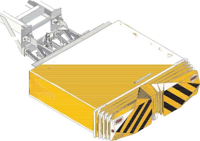
NZTA M23C 2019 | 7

SENTRY II WATER-CABLE BARRIER SYSTEM

 SUMMARY

 SUPPLIER:                              Roadsigns and Traffic Control Equipment (RTL) Ltd             (https://www.rtl.co.nz)

 TEST LEVEL / CONDITIONS:               NCHRP350 TL2 / MASH TL3

 PRODUCT MANUAL                         click for product manual download

 FOR USE WITH                           The SLED-US (page27) water-filled, non-redirective, gating crash cushion is the ONLY crash cushion
                                        currently accepted as an end protection

The Sentry Water-Cable Barrier is a plastic, water-filled portable longitudinal barrier used to provide positive protection in the work zone. The
system utilizes water dispersion upon impact in combination with internal molded-in steel cables. Upon impact, the plastic container ruptures and
disperses the contained water. Simultaneously, the internal cables provide the strength to safely catch the misguided vehicle like a net, preventing
vehicle intrusion into the work zone.
The Sentry is designed to form a series of individual sections linked together to function as a portable longitudinal barrier to keep vehicles from
penetrating the linked barrier sections. The Sentry provides positive separation from the vehicles on the roadway and workers in the work zone.
When an impacting vehicle contacts the Sentry Water-Cable Barrier, the water and internal molded in steel cables act together to re-direct or bring
the impacting vehicle to a controlled stop.
All Sentry Water-Cable Barrier sections should be orange in colour and contain internal molded-in steel cables. Any other colour, or product
without internal molded in cables, will not qualify as a Sentry Water-Cable Barrier product.
In-service impact deflection in excess of the test values indicated below must be allowed for in any temporary traffic management plan utilising the
Sentry Water-Cable Barrier System. All relevant minimum requirements of CoPTTM in regard to working spaces and safety zones must be met
irrespective of the variant in use, in particular the test level of the system must meet or exceed the test level required for the operating speed of
the adjacent traffic (refer CoPTTM B12.1).

 TECHNICAL INFORMATION

 DIMENSIONS                          1924mm length (pin to pin)
                                     571mm width , 1084mm height

 WEIGHT                              72.6kg (empty)
                                     907kg (full)

  MINIMUM LENGTH                     25 units (approximately 48m)

 MINIMUM RADIUS                      5.5m

 WATER FILL CAPACITY                 832 litres

 WATER FILL HOLE SIZE                203mm

 GRADE OR PLACEMENT                  The foundation is required to support the weight of the fully loaded sections e.g. Concrete, asphalt, dirt and
 RESTRICTIONS                        gravel.
NZTA M23C 2019 | 8
DEFLECTION NCHRP-350 TL2: 1.8m (70 km/h, 25°, 2000kg vehicle)
MASH TL3: 2.9m (100 km/h, 25°, 2270kg vehicle)
CLEAR AREA 6m x 18.5m clear area (end terminal clear area) to enable the system to gate if hit downstream from
the head
OTHER RESTRICTIONS / There should be periodic checking of the water level to ensure that it is filled to the proper level.
CONSIDERATIONS All units MUST be connected with the appropriate steel connecting pin and filled with water when in
use.
OTHER CONSIDERATIONS
• Repairing a crack or hole does not return the plastic to its original strength, although most repairs are sufficient to insure a water tight section
(the System Supplier’s product guidelines provide instructions on the viability of minor repairs).
• In freezing weather conditions, allowing the water to freeze to a solid mass of ice should not be allowed. If the temperature at the site is
expected to be at or below the freezing point of water, it is recommended that an additive be used.
• Maximum dynamic deflection at point of impact shall not exceed 3.7 m when impacted at the design speed of TL-3 100 km/h utilizing the
2000 kg vehicle.
• Both systems, Sentry and SLED, MUST be installed and maintained in accordance with their relevant product installation/maintenance
manuals and relevant NZ Transport Agency specifications (including CoPTTM).
• Should the SLED end treatment component NOT be fitted, the barrier system will be considered non-compliant.
•
NOTES:NZTA M23C 2019 | 9
TRAFFIX WATER CABLE MASH TL2 BARRIER + SLED MINI END TREATMENT
SUMMARY
SUPPLIER: CSP Pacific (http://www.csppacific.co.nz)
Roadsigns and Traffic Control Equipment (RTL) Ltd (https://www.rtl.co.nz)
TEST LEVEL / CONDITIONS: MASH TL1 and TL2
PRODUCT MANUAL click for product manual download
TrafFix Water Cable Barrier MASH TL-2 is a plastic, water filled portable barrier system that provides positive protection to the work zone by
redirecting a vehicle and bringing it to a controlled stop. The MASH TL-2 uses water dispersion in combination with moulded-in steel cables. Upon
impact, the plastic module ruptures and disperses the contained water to prevent vehicle intrusion into the work zone. Simultaneously, the steel
cables provide the strength to safely catch the misguided vehicle, preventing vehicle intrusion into the work zone.
The TrafFix Water Cable Barrier connects directly to the SLED Mini End Treatment which negates the need to shield or flare the ends of the barrier.
Only the SLED Mini End Treatment may be used with this product.
TrafFix Water Cable Barrier has been tested and evaluated as per the evaluation criteria in the MASH guidelines for a longitudinal barrier. The
impact conditions recommended in MASH are intended to address typical in-service collisions.
The Water Cable Barrier is designed to replace the in service Water Wall TL1 barrier system (refer page 11 and 12) thanks to its acceptance under
MASH requirements, and superior ribbon strength provided by the integral cable system.
TECHNICAL INFORMATION
DIMENSIONS Width: 4570 mm
Height: 812 mm
Length Weight: 1854 mm pin to pin
WEIGHT Empty Weight: 45.4 kg
Filled Weight: 500 kg
MINIMUM LENGTH 12 units
LENGTH OF NEED 12 units plus end treatment
WATER FILL CAPACITY 466 litres
WATER FILL HOLE 203mm
DIAMETER
GRADE OR PLACEMENT A maximum approach and cross slope of 1:10 is preferable. On slopes greater than this approval is
RESTRICTIONS required from the road controlling authority.
Do not install in front, behind or on a curb. Approval is required from the road controlling authority
otherwise.
DEFLECTION TL2 - 5.47m (70 km/h, 25°, 2270kg vehicle)NZTA M23C 2019 | 10
OTHER RESTRICTIONS/ All units must be connected with the appropriate steel connecting pin and filled with water when in
CONSIDERATIONS use.
The adjacent road operating speed must be limited to 70 km/h and the installation should endeavour
to minimise the impact angles to 25° (1 lateral : 2.14 forward).
The TrafFix Water Cable Barrier is installed with the SLED Mini End Treatment. By exception if the
SLED Mini End Treatment is not used, the end of the barrier must be shielded or flared. The water
level should be checked periodically to ensure that each section is properly filled. The TrafFix Water
Cable Barrier is not fully effective unless each section is filled.
Site specific grading may be necessary to ensure that there are no “humps” or “hollows” that may
significantly alter the impacting vehicles stability or substantially alter the barrier height in relation to
the ground.
OTHER CONSIDERATIONS
• All installers must be well clear of the water tanker when the units are being filled. TrafFix Water Cable Barrier is a stand-alone barrier and does
not require at any stage during installation that the surrounding soil be dug or drilled in anyway.
• TrafFix Water Cable Barrier can be used in both ‘roadside’ and ‘median’ applications.
• It is recommended TrafFix Water Cable Barrier be installed on a compacted surface. Appropriate surfaces for installation include concrete,
asphalt, dirt and gravel surfaces.
• There are no tools required to install the TrafFix Water Cable Barrier components. The units can be manually lifted and positioned by two
personnel and the T-pin used to connect the units is simply dropped into position.
• Ensure that sufficient width and traffic control is available before installing TrafFix Water Cable Barrier.
• Check that there are no leaks before filling the next unit. If there is a leak the unit must be replaced. It may be possible to fix at a later stage
depending on the damage. Refer the Maintenance and Repair section.
• Depending on location, delineation may be required as per Road Controlling Authority guidelines.
NOTES:NZTA M23C 2019 | 11
WATER-WALL TL1 PLASTIC BARRIER + MINI-SLED TL1 PLASTIC END TERMINAL
SUMMARY
SUPPLIER: CSP Pacific (http://www.csppacific.co.nz)
TEST LEVEL / CONDITIONS: NCHRP350 TL1
PRODUCT MANUAL click for product manual download
The Water-Wall TL1 barrier system is a plastic, water-filled portable barrier used to provide positive protection in the work zone. It is designed to
form a series of individual sections linked together to function as a portable longitudinal barrier to keep vehicles from breaching the linked barrier
sections. When an impacting vehicle contacts the TL-1Water-Wall, it is brought to a controlled stop or redirected.
TL1 Water Wall has been tested in accordance with NCHRP Report 350 and complied with the required evaluation criteria for Test Level 1 (TL1).
The FHWA issued a letter of acceptance B-130 (December 2004) for the use of the Water-Wall TL1 temporary barrier system.
The Mini-SLED temporary crash cushion system has been tested in accordance with MASH criteria and complied with the required evaluation
criteria for Test Level 1 (TL1).
Used together, in the configuration shown below, the Water-Wall temporary barrier and Mini-SLED end treatment comprise an NCHRP350 TL1
temporary barrier system.
In-service impact deflection in excess of the test values indicated below must be allowed for in any temporary traffic management plan utilising the
Water-Wall TL1 barrier system. All relevant minimum requirements of CoPTTM in regard to working spaces and safety zones must be met
irrespective of the variant in use, in particular the test level of the system must meet or exceed the test level required for the operating speed of
the adjacent traffic (refer CoPTTM B12.1).
TECHNICAL INFORMATION
DIMENSIONS 1960m length
460mm width, 822mm height
1854mm effective length
WEIGHT 35kg (empty)
500kg (full)
MINIMUM LENGTH 52.4m minimum total length
(2 x yellow Mini-SLED end treatments and 26 x orange Water-Wall barrier sections)
WATER FILL CAPACITY 465 litres per section
CLEAR AREA 6m x 22.5m clear area to enable the system to gate if hit downstream from the head
GRADE OR PLACEMENT End Treatment not to be placed on cross or approach slopes greater than 10°
RESTRICTIONS
MINIMUM DEFLECTION 2.44m from rear edge of barrier (50 km/h, 2000kg vehicle, 25° angle)
LENGTH OF NEED Mini-SLED plus 7 Water-Wall barrier unitsNZTA M23C 2019 | 12
OTHER RESTRICTIONS / The Water-Wall + Mini-SLED TL1 temporary barrier system may only be used on temporary traffic
CONSIDERATIONS management sites where the permanent posted speed limit is 50 km/h or less and the site is under
temporary traffic management control.
All Water-Wall TL1 temporary barrier system units must be connected with the appropriate steel
connecting pin and filled with water when in use.
If the Mini-SLED TL1 End Treatment component of this system is NOT fitted, the entire barrier system
will be considered non-conforming.
The Yellow SLED module is NOT filled with water.
The Mini-SLED End Treatment must not be attached or anchored to the ground, or any other object.
OTHER CONSIDERATIONS
• Appropriate surfaces for installation of the TL-1 Water-Wall include concrete, asphalt, dirt and gravel surfaces.
• Repairing a crack or hole does not return the plastic to its original strength, although most repairs are sufficient to insure a water tight
section. Monitoring of the repair should be done for a short period after filling to ensure that the repair has been done properly.
• In freezing weather conditions, allowing the water in the TL-1 Water-Wall to freeze to a solid mass of ice should not be allowed. If the
temperature at the installation site is expected to be at or below the freezing point of water, it is recommended that an additive be used
to prevent the water in the TL-1 wall from freezing.
• If treatment of the blunt end of the TL-1 Water-Wall is required, the Mini-SLED TL1 End Treatment must be used.
• The TrafFix Water Wall TL1 Barrier System is being superceded by the TrafFix Water Cable MASH TL2 Barrier (Refer Pages 9 - 10).
Upon MASH standards being mandatory across Road Safety Hardware - the Water Wall TL1 variant will be removed from the
accepted devices list.
NOTES:NZTA M23C 2019 | 13
STEEL BARRIER SYSTEMS (excluding End Treatment)
BG800 STEEL BARRIER SYSTEM
SUMMARY
SUPPLIER: Ingal Civil Products (http://www.ingalcivil.co.nz)
TEST LEVEL / CONDITIONS: MASH TL3 / NCHRP350 TL4
PRODUCT MANUAL click for product manual download
The BG800 Steel Barrier System is a temporary steel barrier system comprising 6m or 12m sections fabricated from galvanised steel panels joined
using a proprietary connection system, terminating with ground anchored end sections protected by the use of a crash cushion.
BG800 is a deformable vehicle restraint system acting as a continuous beam, anchored to the ground at the end of each run through specially
designed terminal sections.
The barrier system is used as a temporary barrier for road construction sites where it can be used for nearside or offside applications to protect
construction sites and construction workforce as a positive form of protection. It can also be used as a positive separation for opposing traffic flows
in a contra-flow situation.
With the versatile shorter barrier sections and radius sections most vertical and horizontal curve alignments can be accommodated so BG800 is just
as useful for the local roads as well as on the State Highway network.
In-service impact deflection in excess of the test values indicated below must be allowed for in any temporary traffic management plan utilising the
BG800 Steel Barrier System (non-MDS variants). All relevant minimum requirements of CoPTTM in regard to working spaces and safety zones
must be met irrespective of the variant in use, in particular the test level of the system must meet or exceed the test level required for the
operating speed of the adjacent traffic (refer CoPTTM B12.1).
TECHNICAL INFORMATION
DIMENSIONS 6m or 12m length per unit
540mm width (base), 235mm (top)
800mm height
WEIGHT 1080kg (12m unit)
MINIMUM LENGTH 18m with no accepted crash cushion connected to the end terminal
60m including end terminals
GRADE OR PLACEMENT Not to be installed on ground of cross slope greater than 8% (1V:8H). On slopes greater than this,
RESTRICTIONS approval is required from the road controlling authority.NZTA M23C 2019 | 14
DEFLECTION STANDARD SYSTEM (60M between anchors)
1.36m at 70 km/h (NCHRP 350 - 2000P at 25°)
1.60m at 100 km/h (NCHRP 350 - 2000P at 25°)
1.74m at 80 km/h (NCHRP 350 - 8000T at 15°)
1.70m at 100 km/h (MASH 2270P at 25°)
LDS SYSTEM (12M between anchors)
0.89m at 100 km/h (NCHRP 350 - 2000P at 25°)
0.42m at 80 km/h (NCHRP 350 – 8000T at 15°)
MDS SYSTEM (6M between anchors)
0.076m at toe of barrier 100 km/h (NCHRP 350 - 2000P at 25°)
WORKING WIDTH STANDARD SYSTEM (60M between anchors)
Not specified
LDS SYSTEM (12M between anchors)
Not specified
MDS SYSTEM (6M between anchors)
Not specified
OTHER RESTRICTIONS / A selection of 0.61m long radius sections are available (typically 5° & 10°). These enable
CONSIDERATIONS installations around tight radii.
If the installation of the BG800 is not able to be flared as per the manual then there must be an
accepted NCHRP 350 TL-3 crash cushion connected to the barrier with a clear area of
6 x 22.5m adjacent to the crash cushion and behind the barrier that is flat and without hazards. In
addition, workers, equipment and materials should be a minimum of 6m behind the barrier.
Depending on location, delineation may be required as per the Road Controlling Authority Guidelines.
BG800 can be installed to a surface which is raised by a curb of no more than 100mm high. If the
barrier is installed next to the curb you must ensure that the curb is out of the clear area and does not
prevent the barrier deflecting as intended.
• The BG800 system has been designed to attach to concrete or asphalt foundations or anchored into soil.
• BG800 MDS requires the addition of steel ‘T-Top’ sections on top of the barrier and must have site specific sign off by the Lead Advisor
Safety (Roads & Roadsides).
• Site specific grading may be necessary to ensure that there are no “humps” or “hollows”.
• It is recommended that the system is installed on a compacted surface.
• The final section at both ends of any BG800 Steel Barrier System installation must be anchored to the pavement in accordance
with the System Supplier’s instructions.
• The maximum spacing between anchor points is 60m to replicate crash test deflections (this may be waived in special circumstances
subject to acceptance in writing to the Lead Advisor Safety (Roads & Roadsides).
• Debris and foreign objects should not be in the clear area.
• Where a BG800 “Gate” unit is to be installed (max gate length = 30m), intermediate anchorage of the up and downstream sections of
standard BarrierGuard must be installed.
• BG800 Steel Barrier System must have one of the following accepted crash cushion installed for protection at both ends:
ABSORB 350
SLED-Euro/SLED-US
QuadGuard CZ
SCI-100 Smart Cushion
Tau-II
• When selecting the crash cushion, the provisions of the Code of Practice for Temporary Traffic Management (CoPTTM) section C18.2.1 must
be considered.
NOTES:NZTA M23C 2019 | 15
DEFENDER 70 STEEL BARRIER SYSTEM
SUMMARY
SUPPLIER: Safe Barriers Pty Ltd. (http://www.safebarriers.com)
TEST LEVEL / CONDITIONS: MASH TL2
PRODUCT MANUAL click for product manual
The Defender 70 Steel Barrier System is a free-standing, ballasted, temporary steel barrier system comprising 3.96m sections fabricated from
galvanised steel. The individual units are ballasted using 3 concrete-filled ballast boxes per unit which are mandatory for compliance. The units are
joined using a proprietary connection system with the ends being protected by the use of an accepted temporary crash cushion.
The system has been tested in accordance with MASH Test Level 2 (2270kg pick-up impacting at 70km/h at 25°) and was accepted by the Austroads
Safety Barrier Assessment Panel (ASBAP) on 6 December 2017.
In-service impact deflection in excess of the test values indicated below must be allowed for in any temporary traffic management plan utilising the
Defender 70 Steel Barrier System. All relevant minimum requirements of CoPTTM in regard to working spaces and safety zones must be met
irrespective of the variant in use, in particular the test level of the system must meet or exceed the test level required for the operating speed of
the adjacent traffic (refer CoPTTM B12.1).
TECHNICAL INFORMATION
DIMENSIONS 3.96m length unit
680mm width (base), 800mm height
MINIMUM LENGTH 105m (freestanding)
GRADE OR PLACEMENT May be placed on concrete, asphaltic concrete or chipseal surfaces.
RESTRICTIONS May not be used on unbound/unsealed surfaces.
DEFLECTION 1.2m (measured from outer edge of foot on workzone side of barrier)
WORKING WIDTH 1.88m (measured from outer edge of foot on workzone side of barrier)
ANCHOR POINT SPACING Not applicable (freestanding system)
MINIMUM DISTANCE TO 1.2m (to be measured from outer edge of foot on workzone side of barrier)
EXCAVATION
FLARE RATE 15V:1H for speed 100 km/h
10V:1H for speed 70 km/h
11V:1H for speed 80 km/h
NOTE: Flare rates above apply inside the shyline. Refer to Austroads Guide to Road Design Part 6,
section 6.3.16NZTA M23C 2019 | 16
OTHER RESTRICTIONS / Each unit must have three concrete-filled ballast boxes fitted to be compliant. Units without ballast
CONSIDERATIONS boxes must not be used.
Flaring across the clear area without a terminal is not permitted.
OTHER CONSIDERATIONS
• Flaring of the Defender 70 Steel Barrier System across a clear area ahead of a worksite without a crash cushion is not permitted.
• The installed system shall include delineation as prescribed by road authority specifications and drawings.
• Defender 70 Steel Barrier System must have one of the following accepted crash cushion installed for protection at both ends.
ABSORB 350 - not permitted as a terminal on a flared installation.
SLED-US
TAU-II
• When selecting the crash cushion, the provisions of the Code of Practice for Temporary Traffic Management (CoPTTM) section C18.2.1
must be considered.
NOTES:NZTA M23C 2019 | 17
DEFENDER BARRIER 100 STEEL SAFETY BARRIER (FS, HC & LDS VARIANTS)
SUMMARY
SUPPLIER: Safe Barriers Pty Ltd. (http://www.safebarriers.com)
TEST LEVEL / CONDITIONS: 100 FS - MASH TL3
100 HC – MASH TL3 & TL4
100 LDS – MASH TL3
PRODUCT MANUAL click for product manual
The Defender 100 Steel Safety Barrier (FS, HC and LDS variants) is a steel safety barrier system manufactured from hot dip galvanised steel and are
intended for use as a temporary barrier system.
The FS (Free-standing) variant is not anchored to the road surface, but utilises anchored crash cushions at either end of the installed length. For the
HC (High Containment) variant, that anchoring is every 48.15m. For the LDS (Low Deflection System) variant, the barrier is anchored to the road
surface every 9.15 metres.
The secure connection of the Defender units is made by interlocking the Male and Female end units together with the insertion of a connection pin
to secure each unit in place. The cross section of the unit is detailed above and consists of a 680mm width base with an 800mm height.
TECHNICAL INFORMATION
DIMENSIONS 3959mm length unit (3900mm effective length)
680mm width (base), 820mm height
MINIMUM LENGTH FS variant - 156m
HC variant - 97.5m with anchors at 48.15m spacing
LDS variant – 78m with anchors at 9.15m spacing
GRADE OR PLACEMENT Pinned variants are suitable for pavements with a minimum thickness of 300mm (150mm AC over
RESTRICTIONS compacted granular sub base), where anchoring shall consist of 500 mm long by 30 mm diameter
pins.
DEFLECTION 100 FS variant
1.9m at 100 km/h (MASH TL-3, 2270kg at 25°)
(measured from outer edge of foot on workzone side of barrier)
100 HC variant
2.30m at 100 km/h (MASH TL-3, 2270kg at 25°)
(measured from outer edge of foot on workzone side of barrier)
2.47m at 100 km/h (MASH TL-4, 10,000kg at 25°)
(measured from outer edge of foot on workzone side of barrier)
100 LDS Variant
0.88m at 100 km/h (MASH TL-3, 2270kg at 25°)
(measured from outer edge of foot on workzone side of barrier)
WORKING WIDTH 100 FS variant – 2.58m (TL-3)
100 HC variant – 2.98m (TL-3) 3.31m (TL-4)
100 LDS variant – 1.56m (TL-3)
ANCHOR POINT SPACING HC System – 48.15m maximum spacing (every 12th barrier)
LDS System - 9.15m maximum spacing (every second barrier)NZTA M23C 2019 | 18
MINIMUM DISTANCE TO 100 FS - 1.9m (TL-3)
EXCAVATION 100 HC - With 48.14m anchor spacing: 2.47m (TL-4)
100 LDS - With 9.15m anchor spacing: 0.88m (TL-3)
FLARE RATE Refer to CoPTTM Section 18.4.2 for required flare rates
When fitted with the required TAU-II end terminal, the terminal end cannot be flared.
OTHER RESTRICTIONS / Flaring across the clear area without a terminal is not permitted.
CONSIDERATIONS
Slope must be limited to 1H:10V (10%) lateral slope (all variants)
A tested transition (as per the manufacturers product manual) must be utilised (and pinned) from
attached TAU-II end terminal.
100 HC and 100 LDS systems utilise identical componentry however have differing pin frequency
requirements.
Installation on top of a kerb is not recommended, however if installed on top of a kerb, all system
components must be free to operate.
First pins must be placed in the first available holes after the approach terminal, and before the
departure terminal.
OTHER CONSIDERATIONS
• The installed system shall include delineation as prescribed by road authority specifications and drawings.
• Maximum horizontal and vertical curvature of the system is 230m. Each 3.9m individual section contains 1° of movement per joint.
• Separate specialist corner components are available
• Defender 100 (all variants) must have one of the following accepted crash cushion installed for protection at both ends:
ABSORB 350 - not permitted as a terminal on a flared installation.
SLED-US
TAU-II
• When selecting the crash cushion, the provisions of the Code of Practice for Temporary Traffic Management (CoPTTM) section C18.2.1 must
be considered.
NOTES:NZTA M23C 2019 | 19
ZONEGUARD STEEL BARRIER SYSTEM
SUMMARY
SUPPLIER: Hill & Smith Pty Lt. (http://www.hsroads.com.au)
TEST LEVEL / CONDITIONS: MASH TL3 / NCHRP350 TL4
PRODUCT MANUAL click for technical data
The ZoneGuard Steel Barrier System is a temporary steel barrier system comprising 12m sections fabricated from galvanised steel panels joined
using a proprietary connection system, terminating with ground anchored end sections protected by the use of a crash cushion.
The system has been tested in accordance with NCHRP Report 350 Test Level 4 (8000kg single unit truck impacting at 80 km/h at 15°), refer FHWA
Letter B-176, and MASH Test Level 3 (2270kg pick-up impacting at 100 km/h at 25°), refer FHWA Letters B-176A. The system was accepted by the
Austroads Safety Barrier Assessment Panel (ASBAP) on 30 June 2014.
In-service impact deflection in excess of the test values indicated below must be allowed for in any temporary traffic management plan utilising the
ZoneGuard Steel Barrier System (non-MDS variants). All relevant minimum requirements of CoPTTM in regard to working spaces and safety
zones must be met irrespective of the variant in use, in particular the test level of the system must meet or exceed the test level required for the
operating speed of the adjacent traffic (refer CoPTTM B12.1).
TECHNICAL INFORMATION
DIMENSIONS 11.85m length unit
700mm width (base), 820mm height (includes rubber pad)
MINIMUM LENGTH 75m with anchors at 65m spacing
60m with anchors at 10.2m spacing – NOTE: requires site specific sign-off from Lead Advisor Safety
(Roads & Roadsides)
GRADE OR PLACEMENT Suitable for unbound granular pavements with a minimum thickness of 350mm, where anchoring shall
RESTRICTIONS consist of 8 x 500 mm long by 30 mm diameter pins.
DEFLECTION Standard System:
1.9m (measured at outer edge of foot on workzone side of barrier)
Minimum Deflection System: requires site specific sign-off from Lead Advisor Safety (Roads & Roadsides)
0.1m (measured at outer edge of foot on workzone side of barrier)
WORKING WIDTH Standard System:
2.6m (measured at outer edge of foot on workzone side of barrier)
Minimum Deflection System:
0.8m (measured at outer edge of foot on workzone side of barrier)
ANCHOR POINT SPACING 65m maximum spacing
MINIMUM DISTANCE TO With 65m anchor spacing: 1.9m
EXCAVATION With 10.2m anchor spacing: 0.4m on concrete pavement
0.7m on flexible pavement
FLARE RATE 15V:1H for speed 100 km/h
10V:1H for speed 70 km/h
11V:1H for speed 80 km/h
NOTE: Flare rates above apply inside the shyline. Refer to Austroads Guide to Road Design Part 6, section 6.3.16NZTA M23C 2019 | 20
OTHER RESTRICTIONS / The use of the minimum deflection variant requires site specific sign off by the Lead Advisor Safety
CONSIDERATIONS (Roads & Roadsides).
The final section at both ends of any ZoneGuard Steel Barrier System installation must be anchored
to the pavement in accordance with the System Supplier’s instructions.
The maximum anchor point spacing limit may be waived in special circumstances subject to
acceptance of an evidence-based application in writing to the Lead Advisor Safety (Roads &
Roadsides).
Barrier should be placed a minimum of 250 mm from the edge of travelled way to avoid
nuisance impacts.
Clear span between anchors of greater than 65m is not permitted.
Flaring across the clear area without a terminal is not permitted.
OTHER CONSIDERATIONS
• Flaring of the ZoneGuard Steel Barrier System across a clear area ahead of a worksite without a crash cushion is not permitted.
• The installed system shall include delineation as prescribed by road authority specifications and drawings.
• ZoneGuard Steel Barrier System must have one of the following accepted crash cushion installed for protection at both ends.
ABSORB 350 - not permitted as a terminal on a flared installation.
QuadGuard CZ - recommended where the permanent posted speed limit is greater than 70 km/h, permitted as a terminal on
a flared installation.
TAU-II - recommended where the permanent posted speed limit is greater than 70 km/h, permitted as a terminal on a
flared installation.
• When selecting the crash cushion, the provisions of the Code of Practice for Temporary Traffic Management (CoPTTM) section C18.2.1
must be considered.
NOTES:NZTA M23C 2019 | 21
CONCRETE BARRIER SYSTEMS (Excluding End Treatment)
DELTA BLOC DB80 K150S CONCRETE BARRIER SYSTEM
SUMMARY
SUPPLIER: JayBro Ltd. (www.jaybro.com.au)
TEST LEVEL / CONDITIONS: MASH TL3
PRODUCT MANUAL click for product manual download
FOR USE WITH Compliant end treatment and/or suitable barrier flare in accordance with CoPTTM
The Delta Bloc DB80 K150S temporary concrete barrier is MASH tested temporary concrete road safety barrier system that uses a keyed wedge
system to join adjacent barrier units. The system is free-standing and does not require pinning or anchoring to the road surface.
In-service impact deflection in excess of the test values indicated below must be allowed for in any temporary traffic management plan utilising the
Delta Bloc DB80 K150S. All relevant minimum requirements of CoPTTM in regard to working spaces and safety zones must be met irrespective of
the variant in use, in particular the test level of the system must meet or exceed the test level required for the operating speed of the adjacent
traffic (refer CoPTTM B12.1).
TECHNICAL INFORMATION
DIMENSIONS 4m length unit or 6m length unit.
606mm width (base), 810mm height
NOTE: 4m and 6m units can be used together interchangeably without any restrictions
WEIGHT 2870kg (4m unit), 4300kg (6m unit)
MINIMUM LENGTH 4m units - 60m minimum total length continuous string
6m units - 108m minimum total length continuous string
MINIMUM RADIUS Using 6m units – 135m horizontal radius, 30m vertical radius (sag curve), 53m vertical radius (crest curve)
GRADE OR PLACEMENT Not to be placed on crossfall of 6% or greater.
RESTRICTIONS
Not to be placed on unstable (mud, un-compacted sand) ground or a surface where the full underside
surface of the barrier is not in contact with the road surface).
Barrier rotation – 7° lateral per section, 4° vertical per section.
DEFLECTION 1.44m from rear edge of barrier (100 km/h, 2270kg vehicle, 25° angle)
WORKING WIDTH 1.94m from rear edge of barrier (100 km/h, 2270kg vehicle, 25° angle)
FLARE RATE 10V:1H maximum (for the system).
NOTE: CoPTTM may require much shallower flare rates based on conditions or situation)
OTHER RESTRICTIONS / Use of 2m DB80 K150S units is restricted to tight radius curves and emergency accesses only.
CONSIDERATIONS Not to be placed on, directly in front, or directly behind a kerb. (if in front - deflection zone must be
present behind. Behind kerb – minimum 3m rearward offset).NZTA M23C 2019 | 22
OTHER CONSIDERATIONS
• Ensure safe and correct lifting and maneuvering of barriers is undertaken. Barrier size and weight means heavy machinery/plant is required.
Ensure product manual and expert advice is sought for installation/removal.
• Any exposed blunt end of the barrier system must be protected if it can be struck. Either an end terminal is required, or the blunt end
must be flared away from the approach direction of traffic beyond the clear area.
NOTE: Flaring the blunt end beyond the clear area this does not necessarily protect the end from being struck. Site specific analysis and
consideration is required.
• Delta Bloc DB80 K150S may be used with the following accepted crash cushions:
ABSORB 350 (for sites with a PPSL less than 70km/h)
TAU-II
QuadGuard II or CZ
SCI-100 Smart Cushion
• Where an end terminal is fitted, it must be connected to the end of the barrier system with an accepted proprietary connection
that is designed for use with an F-shape barrier profile and the utilised end terminal.
• If the barrier system is utilised in conjunction or association with another barrier system (either semi-rigid, rigid or flexible) then
site- specific design and consideration is required (i.e. connection of temporary systems to permanent guardrail installations).
• Delineation is required with this system in the form of retro-reflective orange/black chevrons placed at 10m spacing on the top of
the barriers. This includes the end terminal (if fitted).
NOTES:NZTA M23C 2019 | 23
J-J HOOKS® CONCRETE BARRIER SYSTEM
SUMMARY
SUPPLIER: Tauren Barriers Ltd. (www.taurenbarriers.co.nz)
TEST LEVEL / CONDITIONS: MASH TL3
PRODUCT MANUAL click for product manual download
*current as at 24 Dec 2013. Tauren Barriers. Contact supplier for up-to-date manual
FOR USE WITH TL3 F-shape barrier profile only (not new jersey shape). Compliant end treatment and/or suitable
barrier flare in accordance with CoPTTM
The J-J Hooks® concrete barrier system has FHWA acceptance and has been used in New Zealand as connection system for temporary concrete
barrier units for temporary traffic management barrier systems for over 17 years.
This barrier system, like most temporary systems, relies on ribbon strength (connection of continuous strings of barriers) to generate absorption
and redirection capability. The J-J Hook connections between barriers are key to this ribbon strength and they must be in good condition and
robustly linked. Full contact with the road surface is also key as the friction of the barrier on the road is important for the function of the system.
This system does not require pinning or anchoring to the road surface.
In-service impact deflection in excess of the test values indicated below must be allowed for in any temporary traffic management plan utilising the
JJ-Hooks Barrier System. All relevant minimum requirements of CoPTTM in regard to working spaces and safety zones must be met irrespective of
the variant in use, in particular the test level of the system must meet or exceed the test level required for the operating speed of the adjacent
traffic (refer CoPTTM B12.1).
TECHNICAL INFORMATION
DIMENSIONS 3.6m length unit OR 6m length unit.
606mm width (base), 810mm height
NOTE: 3.6m and 6m units can be used together interchangeably without any restrictions
WEIGHT 2400kg (3.6m unit), 4300kg (6m unit)
MINIMUM LENGTH 43.2m minimum total length continuous string
(12 x 3.6m units or 8 x 6m units)
MINIMUM RADIUS 3.6m units – 30m horizontal radius, 30m vertical radius (sag curve), 53m vertical radius (crest curve)
GRADE OR PLACEMENT Not to be placed on crossfall of 7% or greater.
RESTRICTIONS
Not to be placed on unstable (mud, un-compacted sand) ground or a surface where the full underside
surface of the barrier is not in contact with the road surface).
DEFLECTION 1.2m from rear edge of barrier (100 km/h, 2000kg vehicle, 25° angle)
WORKING WIDTH
FLARE RATE 10V:1H maximum (for the system).
NOTE: CoPTTM may require much shallower flare rates based on conditions or situation)NZTA M23C 2019 | 24
OTHER RESTRICTIONS / Not to be placed on, directly in front, or directly behind a kerb. (if in front - deflection zone must be
CONSIDERATIONS present behind. Behind kerb – minimum 3m rearward offset).
Ensure safe and correct lifting and maneuvering of barriers is undertaken. Barrier size and weight
means heavy machinery/plant is required. Ensure product manual and expert advice is sought for
installation/removal.
OTHER CONSIDERATIONS
• J-J Hook® connections can be damaged during installation and removal and bent. Pre-inspection of these is important and concerns
over J-J Hook® condition should result in that barrier not being used. Removal of the J-J Hook® and re-welding or retro-fitting
is prohibited.
• Any exposed blunt end of the barrier system must be protected if it can be struck. Either an end terminal is required, or the blunt end
must be flared away from the approach direction of traffic beyond the clear area.
NOTE: Flaring the blunt end beyond the clear area this does not necessarily protect the end from being struck. Site specific analysis and consideration
is required.
• J-J Hooks® concrete barrier system may be used with the following accepted crash cushions:
ABSORB 350 (for sites with a PPSL less than 70km/h)
TAU-II
QuadGuard II or CZ
SCI-100 Smart Cushion
• Where an end terminal is fitted, it must be connected to the end of the barrier system with an accepted proprietary connection that is
designed for use with an F-shape barrier profile and the utilised end terminal.
• If the barrier system is utilised in conjunction or association with another barrier system (either semi-rigid, rigid or flexible) then site-
specific design and consideration is required (i.e. connection of temporary systems to permanent guardrail installations).
• Delineation is required with this system in the form of retro-reflective orange/black chevrons placed at 10m spacing on the top of the
barriers. This includes the end terminal (if fitted).
• Barriers must be natural concrete or grey in colour. The barrier units may be painted orange to increase conspicuity if desired.
• Some transitions will provide a JJ transition component - if supplied it must be used.
NOTES:You can also read