TG 0531 - Gravity Network Ventilation Design - SA Water
←
→
Page content transcription
If your browser does not render page correctly, please read the page content below
Engineering

Technical Guideline

TG 0531 - Gravity Network
Ventilation Design

Version: 1.0
Date: 17 February 2021
Status: Final

Document ID: SAWG-ENG-0531

© 2021 SA Water Corporation. All rights reserved. This document may contain
confidential information of SA Water Corporation. Disclosure or dissemination to
unauthorised individuals is strictly prohibited. Uncontrolled when printed or
downloaded.
TG 0531 - Gravity Network Ventilation Design                               SA Water - Technical Guideline

Copyright
       This Guideline is an intellectual property of the South Australian Water Corporation. It is
       copyright and all rights are reserved by SA Water. No part may be reproduced, copied or
       transmitted in any form or by any means without the express written permission of SA Water.
       The information contained in this Guideline is strictly for the private use of the intended
       recipient in relation to works or projects of SA Water.
       This Guideline has been prepared for SA Water’s own internal use and SA Water makes no
       representation as to the quality, accuracy or suitability of the information for any other
       purpose.

Application & Interpretation of this Document
       It is the responsibility of the users of this Guideline to ensure that the application of information
       is appropriate and that any designs based on this Guideline are fit for SA Water’s purposes
       and comply with all relevant Australian Standards, Acts and regulations.
       Users of this Guideline accept sole responsibility for interpretation and use of the information
       contained in this Guideline. Users should independently verify the accuracy, fitness for
       purpose and application of information contained in this Guideline.
       Only the current revision of this Guideline should be used which is available for download
       from the SA Water website.

Significant/Major Changes Incorporated in This Edition
       Nil.
       This is the first issue of this Technical Guideline.

Revision 1.0 – February 2021               Document ID: SAWG-ENG-0531                              Page 2 of 36
For Official Use Only                                                   Uncontrolled when printed or downloaded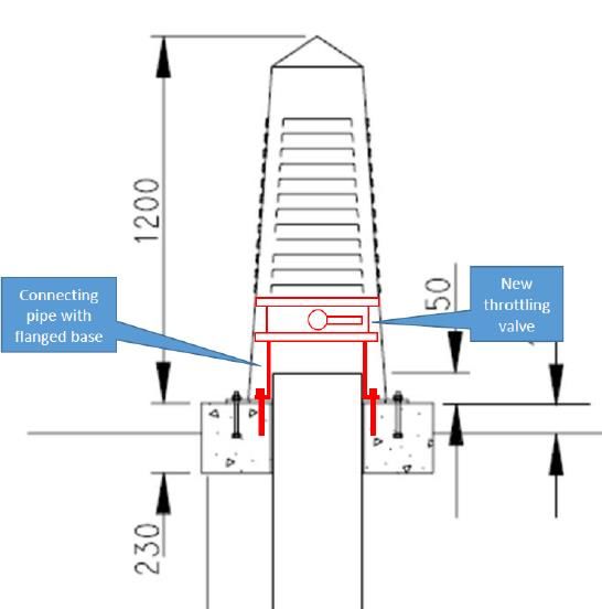
TG 0531 - Gravity Network Ventilation Design                                               SA Water - Technical Guideline

Document Controls

Revision History

         Revision       Date          Author                Comments
            0.1         June 2020     Jacobs                Draft for SA Water review
            0.2         August 2020   Jacobs                Final Draft for SA Water review
            0.3         September     Jacobs                Final
                        2020
            1.0         February      SA Water              Final for Issue
                        2021

       Template: Technical Guideline Version 6.00, 10/05/2016

Approvers
         Role                                                       Signature and Date
         Responsible Discipline Lead                                                                                  1 8 /0 3 /2 0 2 1

         Mark Papadimitriou

                                                                     X          M a r k P a p a d im itr io u
                                                                     S ig n e r's N a m e

                                                                     S ig n e d b y: P A 0 0 4 1 1 7

         Manager Engineering Quality and Innovation                                                                   1 8 /0 3 /2 0 2 1

         Matthew Davis

                                                                     X
                                                                     S ig n e r's N a m e

                                                                     S ig n e d b y: D A 0 0 3 6 8 1

         Senior Manager Engineering Services                                                                         2 2 /0 3 /2 0 2 1

         Richard Gray

                                                                     X
                                                                       S ig n e r ' s N a m e

                                                                       S ig n e d b y : G R 0 0 1 9 6 4

Reviewers
         Role                                             Name                                            Revision     Review Date
         Jacobs Technical Lead                            Josef Cesca                                       0.1          June 2020
         SAW Wastewater Engineering Review                Teresa Qiu                                        0.1            29 June
                                                                                                                            2020
         Jacobs Technical Lead                            Josef Cesca                                       0.2         August 2020
         SAW Wastewater Engineering Review                Teresa Qiu                                        0.2         August 2020
         Jacobs Technical Lead                            Josef Cesca                                       0.3         September
                                                                                                                           2020

Revision 1.0 – February 2021                   Document ID: SAWG-ENG-0531                                                Page 3 of 36
For Official Use Only                                                                Uncontrolled when printed or downloaded
TG 0531 - Gravity Network Ventilation Design SA Water - Technical Guideline
Executive Summary
This Technical Guideline has been developed to assist in the design of ventilation for gravity
sewer networks, and determination of what network ventilation infrastructure is required to
better manage and reduce odour risks.
Understanding ventilation is important to determine where odours may be released from a
sewer and its effect on corrosion within the sewer. Hydrogen sulphide (H 2S) generation in the
sewer coupled with ventilation will result in odour release, and H 2S in the sewer headspace
and low ventilation can cause sewer corrosion.
Sewers naturally aspirate, drawing air in as the water moves downhill dragging the air with the
waterflow. This natural aspiration also provides some degree of aeration as the oxygen in the
headspace is transferred to the sewage. However, if the oxygen transfer is insufficient to keep
the sewage aerobic, anerobic decomposition of the waste occurs and sulphides are
generated that can result in H2S being released to the head space. When the airflow in the
sewer becomes restricted the air is released to atmosphere and causes offensive odour
issues. Sewers require ventilation to promote aerobic conditions and release odour to
atmosphere in a controlled way at locations where pressure in the headspace increases.
Without sufficient appreciation of this, sewer vents can be poorly located or end up being
removed making the problem worse. Pressurisation of the sewer can also cause issues with
boundary traps being sucked out or blown in.
Conditions that result in pressure changes in the sewer headspace are:
• Significant changes in flow level within the sewer, for example at a rising main
discharge
• The presence of a siphon or wet well
• Abrupt changes in sewer size or grade
• The introduction of flow from a significant sidestreams at a junction
Along with providing air release to avoid pressurisation of the sewer, sewer ventilation systems
are generally designed to meet one or more of the following objectives:
• To reduce septicity in the sewer by maintaining a supply of oxygen (reaeration)
• To dry unsubmerged sewer walls to control sulphide-initiated corrosion
• To reduce H2S concentration in the sewer atmosphere
• To control odour emissions and minimise the risk of receiving odour complaints
• To reduce hazards to maintenance personnel through countering the development
of a toxic and/or explosive atmosphere.
This Guideline outlines the details of the following network ventilation infrastructure, including
their application, the associated risks and issues and design criteria:
• Induct/educt vents
• Passive/active carbon filters
• Dampers and throttling valves
• Air curtains
• Fan stations
Natural ventilation via a series of alternately sited induct and educt vents is generally
satisfactory for venting branch and trunk sewers. It should be installed for systems where
sewage is normally fresh (i.e. mainly domestic wastewater and sewer grades are reasonably
steep and frequent branch sewer junctions allow air inflow) or does not tend to be stale or
septic and the sewer is not in close proximity to odour sensitive areas. Most sewers
incorporate some method of natural ventilation, however there are situations where it is not
sufficient.
Revision 1.0 – February 2021 Document ID: SAWG-ENG-0531 Page 4 of 36
For Official Use Only Uncontrolled when printed or downloadedTG 0531 - Gravity Network Ventilation Design SA Water - Technical Guideline
Mechanical ventilation may be required for some larger trunk sewers and where septic
sewage exists, and should be used in situations where:
• Sewage is always septic
• Sewage is either stale or septic and flow turbulence (sewer drops) cannot be avoided
• Sewage is slow flowing or ponding (flat grades) and likely to be stale or septic,
• In locations where frequent odour problems are likely to occur and odour treatment
and/or stack dispersion is critical
In some instances, installation of natural or mechanical ventilation systems alone is sufficient
to minimise the risk of odour complaints from a sewer network. However, in areas where
emissions from the sewer have a negative impact on surrounding receptors, the installation of
mechanical ventilation with odour treatment of extracted air may be warranted. Depending
upon the scale required, an odour control system can require significant capital investment
and ongoing operation and maintenance costs. Therefore, SA Water requires a robust
decision making process to determine when odour control is deemed necessary. This
Guideline outlines drivers for odour control and the assessment of odour control requirements
at sewage pump stations and for new developments.
The Table below provides a quick reference guide for the design of ventilation in gravity
sewer networks to better manage and reduce odour risks, as covered in this Guideline.
Design Consideration Reference
Headspace requirements for natural ventilation Section 3.3.1
The use of controlled versus uncontrolled natural ventilation Section 3.3.2
Design requirements for locating vents for natural ventilation Section 3.3.3
Induct and educt design Section 4.23.3.4
Carbon filter application and risks Sections 4.3.1 and 4.3.2
Application of passive carbon filters Section 4.3.1.1
Application of active carbon filters Section 4.3.1.2
Design criteria for passive and active carbon filters Section 4.3.3
Requirements for dampers and throttling valves Section 4.4
Suitability of air curtains Section 4.5
The use of fan stations and the associated risks/issues Sections 4.6.1 and 4.6.2
Design criteria for ventilation (fan stations) on sewers Section 4.6.3.1
Basis for sizing air flows for sewer ventilation (fan station) Table 4-5
Ventilation rates for sewage pump stations Section 4.6.3.2
Guidelines for use of natural and mechanical ventilation Section 5.4
Drivers for odour control Section 6.2
Assessment of general odour control requirements Section 6.3.1
Odour control assessment - risk factors and ranking guidance Table 6-1
Odour control requirements at sewage pump stations Section 6.3.2
Odour control requirements for new developments Table 6-2
Screening and design criteria for installation of passive green domes Table 6-3
at sewage pump stations
Revision 1.0 – February 2021 Document ID: SAWG-ENG-0531 Page 5 of 36
For Official Use Only Uncontrolled when printed or downloadedTG 0531 - Gravity Network Ventilation Design SA Water - Technical Guideline
Contents
1 Introduction ........................................................................................................ 8
1.1 Purpose .......................................................................................................... 8
1.2 Glossary ......................................................................................................... 8
1.3 References .................................................................................................... 8
1.3.1 Australian and International .................................................................... 8
1.3.2 SA Water Documents ............................................................................... 9
1.4 Definitions ...................................................................................................... 9
2 Scope ............................................................................................................... 10
3 Natural Ventilation Design .............................................................................. 11
3.1 Introduction ................................................................................................. 11
3.2 The Need for Ventilation ............................................................................ 13
3.3 Basic Rules for Natural Ventilation Design in Gravity Sewers ................... 14
3.3.1 Headspace Requirements for Natural Ventilation .............................. 14
3.3.2 Controlled and Uncontrolled Natural Ventilation Systems ................. 14
3.3.3 Locating Vents........................................................................................ 16
3.3.4 Vent Design ............................................................................................ 17
4 Network Ventilation Infrastructure and Design Criteria ................................ 18
4.1 Introduction ................................................................................................. 18
4.2 Induct/Educt Vents ..................................................................................... 18
4.2.1 Inducts ..................................................................................................... 18
4.2.2 Educts ...................................................................................................... 19
4.2.3 Risks/Issues ............................................................................................... 19
4.2.4 Design Criteria ........................................................................................ 20
4.3 Passive/Active Carbon Filters ..................................................................... 22
4.3.1 Description and Application ................................................................. 22
4.3.2 Risks/Issues ............................................................................................... 23
4.3.3 Design Criteria ........................................................................................ 25
4.4 Dampers and Throttling Valves .................................................................. 25
4.5 Air Curtains .................................................................................................. 26
4.6 Fan Stations ................................................................................................. 26
4.6.1 Description and Application ................................................................. 26
4.6.2 Risks/Issues ............................................................................................... 27
4.6.3 Design Criteria ........................................................................................ 27
5 Natural and Mechanical Ventilation ............................................................. 30
5.1 Introduction ................................................................................................. 30
5.2 Comparison of Natural and Mechanical Ventilation .............................. 30
5.3 Odour Control vs Corrosion Control .......................................................... 30
5.4 Guidelines for Application ......................................................................... 31
5.5 Design Considerations ................................................................................ 31
Revision 1.0 – February 2021 Document ID: SAWG-ENG-0531 Page 6 of 36
For Official Use Only Uncontrolled when printed or downloadedTG 0531 - Gravity Network Ventilation Design SA Water - Technical Guideline
6 The Need for Odour Control ........................................................................... 32
6.1 Introduction ................................................................................................. 32
6.2 Drivers for Odour Control............................................................................ 32
6.3 Assessment of Odour Control Requirements ............................................ 33
6.3.1 General Method..................................................................................... 33
6.3.2 SPS ........................................................................................................... 34
6.3.3 New Developments ............................................................................... 34
7 References ....................................................................................................... 36
List of figures
Figure 3-1 Mechanisms Affecting Sewer Ventilation ............................................. 12
Figure 3-2 Sewer Ventilation at Siphons and SPS ................................................... 13
Figure 3-3 Uncontrolled Natural Ventilation [2] ...................................................... 15
Figure 3-4 Controlled Natural Ventilation [2] .......................................................... 15
Figure 4-1 Induct ....................................................................................................... 18
Figure 4-2 Retrofitting of Damper on Existing Induct and Fitting of Temporary Extension
Pipe .............................................................................................................. 19
Figure 4-3 Passive AC Filter on Educt ...................................................................... 22
Figure 4-4 Low Pressure Carbon Filter (Green Dome) ............................................ 23
Figure 4-5 Fan Station Zone of Influence ................................................................ 26
List of tables
Table 4-1 Educt Diameter Selection........................................................................ 20
Table 4-2 Educt Diameters (SS316) .......................................................................... 20
Table 4-3 Educt Vent Heights .................................................................................. 21
Table 4-4 Example Evaluation of Carbon Filters for Specific Situations ................ 24
Table 4-5 Basis for Sizing Air Flow of Sewer Fan Station .......................................... 27
Table 6-1 Risk Factors and Ranking Guidance....................................................... 33
Table 6-2 Odour Control Requirements .................................................................. 34
Table 6-3 Screening Criteria for the Installation of Passive Green Domes on SPSs35
Revision 1.0 – February 2021 Document ID: SAWG-ENG-0531 Page 7 of 36
For Official Use Only Uncontrolled when printed or downloadedTG 0531 - Gravity Network Ventilation Design SA Water - Technical Guideline
1 Introduction
SA Water is responsible for operation and maintenance of an extensive amount of sewerage
infrastructure.
This guideline has been developed to assist in the design of ventilation for gravity sewer
networks, and determination of what network ventilation infrastructure is required to better
manage and reduce odour risks.
1.1 Purpose
The purpose of this guideline is to provide guidance for the design of ventilation for gravity
sewer networks, and determination of what network ventilation infrastructure is required to
better manage and reduce odour risks.
1.2 Glossary
The following glossary items are used in this document:
Term Description
AC Activated carbon
HRT Hydraulic Retention Time
H2S Hydrogen Sulphide
ID Internal Diameter
OCS Odour Control System
OD Outer Diameter
O&M Operation and Maintenance
PDWF Peak Dry Weather Flow
SA Water South Australian Water Corporation
SPS Sewage Pumping Station
TG SA Water Technical Guideline
TS SA Water Technical Standard
WSAA Water Services Association of Australia
1.3 References
1.3.1 Australian and International
The following table identifies Australian and International standards and other similar
documents referenced in this document:
Number Title
1 Water Services Association of Australia (WSAA), 2017. Sewerage Code of Australia. WSA 02-
2002-2.2 Sydney Water Edition Version 4.
2 H2S Control Manual, 1989 – Technological Standing Committee on Hydrogen Sulphide
Corrosion in Sewerage Works. Hydrogen Sulphide Control Manual: Septicity, Corrosion and
Odour Control in Sewerage Systems. Volume 1. Melbourne and Metropolitan Board of
Works.
3 US EPA, 1985. Design Manual: Odor and Corrosion Control in Sanitary Sewerage Systems
and Treatment Plants. Centre for Environmental Research Information.
Revision 1.0 – February 2021 Document ID: SAWG-ENG-0531 Page 8 of 36
For Official Use Only Uncontrolled when printed or downloadedTG 0531 - Gravity Network Ventilation Design SA Water - Technical Guideline
1.3.2 SA Water Documents
The following table identifies the SA Water guidelines and other similar documents referenced
in this document:
Number Title
4 TG 0530 – Sewer Network Hydraulic Design Consideration to Minimise Network Odour
Impact
1.4 Definitions
The following definitions are applicable to this document:
Term Description
Green dome Low pressure activated carbon (AC) filters installed at ground level
designed to capture odours and volatile gases from air vented pump
stations, air release valves, sewers and tanks.
Trunk Sewer Sewers with a nominal diameter of greater than 600mm
Branch Sewer Sewers with a nominal diameter between 375mm and 600mm
Reticulation Sewer Sewers with a nominal diameter 100mm to 300mm
SA Water’s Representative The SA Water representative with delegated authority under a Contract
or engagement, including (as applicable):
• Superintendent’s Representative (e.g. AS 4300 & AS 2124 etc.)
• SA Water Project Manager
• SA Water nominated contact person
Responsible Discipline Lead The engineering discipline expert responsible for TG0531 defined on
page 3 (via SA Water’s Representative)
Revision 1.0 – February 2021 Document ID: SAWG-ENG-0531 Page 9 of 36
For Official Use Only Uncontrolled when printed or downloadedTG 0531 - Gravity Network Ventilation Design SA Water - Technical Guideline
2 Scope
This guideline has been developed to assist in the design of ventilation for gravity sewer
networks, and determination of what network ventilation infrastructure is required to better
manage and reduce odour risks.
Each of the following design aspects are outlined in a separate section in the Guideline:
1. Natural ventilation design
2. Details of network ventilation infrastructure and design criteria, including:
a. Induct/educt vents
b. Passive/active carbon filters
c. Dampers and throttling valves
d. Air curtains
e. Fan stations
3. The need for natural versus mechanical ventilation in the sewer
4. The need for odour control
Revision 1.0 – February 2021 Document ID: SAWG-ENG-0531 Page 10 of 36
For Official Use Only Uncontrolled when printed or downloadedTG 0531 - Gravity Network Ventilation Design SA Water - Technical Guideline
3 Natural Ventilation Design
3.1 Introduction
Understanding ventilation is important to determine where odours may be released from a
sewer and its effect on corrosion within the sewer. Hydrogen sulphide (H2S) generation in the
sewer coupled with ventilation will result in odour release, and H 2S in the sewer headspace
and low ventilation can cause sewer corrosion.
There have been several empirical algorithms proposed for predicting natural ventilation air
movements, the most popular being the Pescod & Price Equation [5], but these have not
been widely used for the ventilation of sewers as the results have been mixed. Design of
natural ventilation systems have sometimes failed to protect nearby residents from escaping
odours and in many cases the vents have been either closed or forced ventilation systems
installed.
The natural forces influencing ventilation are a fine balance between:
• Relative density between sewer air and outside air
• Wastewater flow induced drag
• Friction on pipe walls
• Changes in barometric pressures along a sewer
• Wind velocities over ventilation stacks
These 5 basic mechanisms that affect sewer ventilation are shown in Figure 3-1.
This Section describes the need for sewer ventilation and the basic rules for natural ventilation
in gravity sewers.
Mechanism Explanation
Friction drag by flowing sewage
• Air is dragged with sewage
• During high flows the water level rises
above the outlet forcing the air to
escape through the manhole
Revision 1.0 – February 2021 Document ID: SAWG-ENG-0531 Page 11 of 36
For Official Use Only Uncontrolled when printed or downloadedTG 0531 - Gravity Network Ventilation Design SA Water - Technical Guideline
Mechanism Explanation
Changes in water velocity and depth
• Sewage accelerates down the steep
incline and slows at the bottom forcing
excess air out
Temperature gradients and buoyancy
• Occurs particularly at night with low flows
warm air escapes through manholes and
vents and sometimes is displaced with
colder more dense air
Wind eduction
• Wind moving across vents will cause a
venturi effect sucking odorous air out.
• High pressure situation can also pressurise
sewers which will cause odour escape
downstream.
• This is less of a problem as winds will dilute
odours. Exceptions are high initial odour
concentrations and / or weak winds,
which result in impacts on community.
Bottlenecks
• Bottle necks restrict headspace and
occur at sewage pump stations (SPS),
siphons without an air jumper, and
manholes.
• All the air must escape at these locations
Figure 3-1 Mechanisms Affecting Sewer Ventilation
Revision 1.0 – February 2021 Document ID: SAWG-ENG-0531 Page 12 of 36
For Official Use Only Uncontrolled when printed or downloadedTG 0531 - Gravity Network Ventilation Design SA Water - Technical Guideline
3.2 The Need for Ventilation
Sewers naturally aspirate, drawing air in as the water moves downhill dragging the air with the
waterflow. This natural aspiration also provides some degree of aeration as the oxygen in the
headspace is transferred to the sewage. However, if the oxygen transfer is insufficient to keep
the sewage aerobic, anerobic decomposition of the waste occurs and sulphides are
generated that can result in hydrogen sulphide gas (H2S) being released to the head space.
When the airflow in the sewer becomes restricted the air is released to atmosphere and
causes offensive odour issues. Sewers require ventilation to promote aerobic conditions and
release odour to atmosphere in a controlled way at locations where pressure in the
headspace increases. Without sufficient appreciation of this, sewer vents can be poorly
located or end up being removed making the problem worse. Pressurisation of the sewer can
also cause issues with boundary traps being sucked out or blown in.
Conditions that result in pressure changes in the sewer headspace are:
• Significant changes in flow level within the sewer, for example at a rising main discharge
• The presence of a siphon or wet well
• Abrupt changes in sewer size or grade
• The introduction of flow from a significant sidestreams at a junction
Figure 3-2 below demonstrates the natural path of air released from a sewer caused by a
restriction from a siphon and a SPS.
Figure 3-2 Sewer Ventilation at Siphons and SPS
Along with providing air release to avoid pressurisation of the sewer, sewer ventilation systems
are generally designed to meet one or more of the following objectives:
• To reduce septicity in the sewer by maintaining a supply of oxygen (reaeration)
• To dry unsubmerged sewer walls to control sulphide-initiated corrosion
• To reduce H2S concentration in the sewer atmosphere
• To control odour emissions and minimise the risk of receiving odour complaints
• To reduce hazards to maintenance personnel through countering the development
of a toxic and/or explosive atmosphere.
Revision 1.0 – February 2021 Document ID: SAWG-ENG-0531 Page 13 of 36
For Official Use Only Uncontrolled when printed or downloadedTG 0531 - Gravity Network Ventilation Design SA Water - Technical Guideline
3.3 Basic Rules for Natural Ventilation Design in Gravity Sewers
It is preferable to employ natural ventilation patterns to promote air movement in a gravity
sewer. Natural ventilation of sewers is achieved through the installation of vents along a
sewer, with inducts to allow fresh air to enter the sewer and educts to allow release of air from
the sewer.
The minimum headspace requirements and basic rules for locating of vents are outlined
below.
3.3.1 Headspace Requirements for Natural Ventilation
To ensure the efficiency of natural ventilation of a sewer, the Water Services Association of
Australia (WSAA) Sewerage Code of Australia [1] recommends that an air space be retained
at either the peak dry weather flow (PDWF) or the design flow.
• Option A - Air space at PDWF
• At PDWF, the depth of flow shall be not more than 60% of the pipe diameter i.e.
a minimum air space equivalent to 40% of pipe diameter at PDWF
• Option B - Air space at design flow (this option caters for future growth or phased
development)
• At design flow, the depth of flow shall be not more than 70% of pipe diameter
i.e. a minimum air space equivalent to 30% of pipe diameter at design flow.
• Option C – No air space at design flow and ratio of PDWF to pipe full capacity does not
exceed 0.6.
It is noted that there are also conditions in a sewage network that can cause a pipe to
surcharge completely restricting the sewer headspace (such as a rising main release
location) that also need to be considered.
Option A is the preferred approach.
3.3.2 Controlled and Uncontrolled Natural Ventilation Systems
Natural ventilation can be achieved using uncontrolled or controlled systems [2].
An uncontrolled natural ventilation system consists of alternating short induct and tall educt
vents, designed to maximise the effect of wind flow and air relative density effect. In these
systems air flow in each adjacent section of sewer is in opposite directions with each educt
vent pulling most of the air from the upstream section and the remainder from the
downstream section (against sewage flow). A downside of having air and sewage flow in
opposite directions downstream of educts is that the relative velocity of air increases and thus
H2S emissions and evaporation also increase. The combination of higher H2S concentration
and higher humidity increases the possibility of wet walls and corrosion. Figure 3-3 provides a
graphical representation of uncontrolled ventilation.
Revision 1.0 – February 2021 Document ID: SAWG-ENG-0531 Page 14 of 36
For Official Use Only Uncontrolled when printed or downloadedTG 0531 - Gravity Network Ventilation Design SA Water - Technical Guideline
Figure 3-3 Uncontrolled Natural Ventilation [2]
Controlled natural ventilation systems are designed to encourage airflow in the direction of
sewage flow. Each ventilation shaft is divided into educt and induct zones using suitable
ducting and bulkheads to prevent short-circuiting of air flow. These systems have lower
relative velocity between the liquid and vapour phase, which minimises H2S emissions and
evaporation. The use of flexible bulkheads promotes total air exchange in each ventilated
section, aiming to minimise the build-up of H2S and humidity in the air flowing through the
sewer. However, the use of these bulkheads adds additional complexity to sewer design and
additional maintenance requirements and are not commonly employed. Figure 3-4 provides
a graphical representation of controlled ventilation.
Figure 3-4 Controlled Natural Ventilation [2]
Revision 1.0 – February 2021 Document ID: SAWG-ENG-0531 Page 15 of 36
For Official Use Only Uncontrolled when printed or downloadedTG 0531 - Gravity Network Ventilation Design SA Water - Technical Guideline
3.3.3 Locating Vents
The maximum recommended nominal spacing of vents along a trunk or branch sewer is
400m [1]. Inducts are required where the incoming sewers do not provide enough movement
of free air to avoid pressurisation
The siting of vents must also consider the hydraulic conditions in sewers to ensure proper
ventilation. In addition to the above maximum nominal spacing, vents shall also be installed
on trunk, branch and reticulation sewers at the following locations:
• At rising main discharge manholes
• At siphons (see Figure 3-1):
• Educt shall be installed at the upstream end of a siphon, immediately upstream
of where surcharging of the sewer occurs
• Induct downstream of the siphon
• Where sewer grade changes significantly (see Figure 3-1):
• Induct at the top of the slope
• Educt at the bottom of the slope. For large or trunk sewers, a passive carbon filter
can be preferable to an uncontrolled educt1.
• At SPS
• Educt vents or air valves are typically fitted at high points in pipelines and rising mains that
are running full to prevent build-up of gases [4].
Consideration should also be given to the following when locating vents [1]:
• Locate vents above the 1:20 year flood level or else the base to be built up to flood level
• Locate vents outside the zone of influence of future sewer inlets
• Locate vents on high ground above the level of adjacent inhabited areas
• When high ground is not available, vents should be located at the most exposed
sites, or in places where full advantage can be taken of high wind velocities;
• Vent locations near tree canopies should be avoided, as these can detain
odour and inhibit good dispersion of odours leaving the vent. If a vent needs to
be amongst trees, the stack height should be at least 3 m above the canopy.
• Locate vents as far as practicable from houses and other habitable areas, especially
where buildings are likely to be more than one storey high.
While there are no hard and fast rules for where to avoid installing inducts, the following risk
factors should be considered when they apply, either on their own or in combination:
• Proposed induct is near residences
• Locations where the sewer is at risk of being pressurised:
o Such as the following;
▪ SPS
▪ drop structure
▪ sudden change in grade from steep to shallow
▪ sudden reduction in sewer size near the proposed location and there
are few or no educts or sidestreams immediately upstream
1This is due to SA Water’s past experience with educts under these conditions releasing significant
odour. Note that a passive carbon filter may need to be changed to an active version if air flow in the
sewer reduces.
Revision 1.0 – February 2021 Document ID: SAWG-ENG-0531 Page 16 of 36
For Official Use Only Uncontrolled when printed or downloadedTG 0531 - Gravity Network Ventilation Design SA Water - Technical Guideline
o The sewer joins to a trunk sewer downstream which is minimally ventilated
o The sewer has been lined with a plastic liner, making it less leaky and so
magnifying air pressure surges.
o Pressure monitoring of the sewer could help diagnose if this is an issue before
the induct is installed.
3.3.4 Vent Design
Vent design is outlined in Section 4.2.
Ventilation infrastructure and equipment should be made from non-corrosive materials [4].
The use of uncoated mild steel or galvanised mild steel should be avoided.
Revision 1.0 – February 2021 Document ID: SAWG-ENG-0531 Page 17 of 36
For Official Use Only Uncontrolled when printed or downloadedTG 0531 - Gravity Network Ventilation Design SA Water - Technical Guideline
4 Network Ventilation Infrastructure and Design
Criteria
4.1 Introduction
There are numerous types of infrastructure associated with sewer ventilation, including:
• Inducts/educt vents
• Passive/active carbon filters
• Dampers and throttling valves
• Air curtains
• Fan stations
This Section provides a description of each of the items above, along with details of their
application, associated risks and any relevant design criteria.
4.2 Induct/Educt Vents
Vent shafts are typically above ground structures that either:
• Admit air into the sewer system (induct vents) to reduce the likelihood of sewage
becoming septic or corrosive and causing odour issues; or
• Allow odours to escape (educt vents) and be dispersed
The combination of these vents promotes natural draft from the ground-level induct to the tall
stack educt.
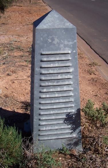
4.2.1 Inducts
SA Water’s standard induct vent stands 1.2m high, and contains louvres to facilitate entry of
air into the sewer. The maximum allowable offset distance from the vented sewer or structure
to an induct is 20m. Figure 4-1 shows a photograph of an induct and an isometric drawing. SA
Water’s standard general arrangement for an induct vent is shown on Drawing 4005-20007-
05.
Figure 4-1 Induct
Revision 1.0 – February 2021 Document ID: SAWG-ENG-0531 Page 18 of 36
For Official Use Only Uncontrolled when printed or downloadedTG 0531 - Gravity Network Ventilation Design SA Water - Technical Guideline
Note that the standard induct uses a DN100 connection pipe; it may be necessary to
increase the number of inducts or else increase the size of the connection pipe for trunk
sewers to provide for their ventilation requirements.
New inducts are to be fitted with dampers to allow throttling of inlet air. In the case of existing
inducts, dampers can be retrofitted as required. Where air measurements will be required at
an induct, design shall include a PVC stub flange on top of the retrofitted damper to enable
attachment of a temporary extension pipe (during commissioning only) to facilitate induct
airflow measurements and negative pressure readings. These requirements are shown in
Figure 4-2 below [4].
Figure 4-2 Retrofitting of Damper on Existing Induct and Fitting of Temporary Extension Pipe
4.2.2 Educts
SA Water standard educts are 15m tall with a diameter of 300mm and are constructed from
either glass reinforced plastic or stainless steel [4]. The maximum allowable offset distance
from the vented sewer or structure to the educt is 20m.
Unpainted stainless steel vents are recommended for better durability and lower
maintenance. However, painting of vents may be required for aesthetic reasons.
SA Water’s standard general arrangement for an educt vent is shown on Drawing 4005-
20007-06.
4.2.3 Risks/Issues
Risks and issues associated with ventilation of the sewer using inducts/educts are as follows:
• Uncontrolled systems may generate air flow in the opposite direction to the wastewater
flow downstream of educts, resulting in reduced effectiveness and sometimes an increase
in odour emissions [2].
• System may not work reliably due to low sewage gas temperatures or a lack of wind
passing over the vents. Wind driven rotary cowls may increase draft, however they are not
always effective [4].
Revision 1.0 – February 2021 Document ID: SAWG-ENG-0531 Page 19 of 36
For Official Use Only Uncontrolled when printed or downloadedTG 0531 - Gravity Network Ventilation Design SA Water - Technical Guideline
• Natural ventilation by inducts and educts is generally not sufficient for corrosion control as
ventilation rates are not high enough to maintain dry pipe walls, thus all exposed surfaces
should be manufactured from non-corrosive materials [1].
• Inducts can operating as educts under different flow scenarios in the sewer, which can
result in odour emissions close to ground level.
4.2.4 Design Criteria
4.2.4.1 Location
Guidelines for locating inducts and educts are outlined in Section 3.3.3.
4.2.4.2 Sizing
Educt vents should have a diameter equal to that of the sewer for sewers with a diameter of
less than 300mm. Greater than this, they need to be specifically designed [8]. Melbourne
Retail Water Agencies indicate that 300mm would be suitable for all of the network for sewers
up to DN750, as the default vent diameter that is normally selected is approximately half the
diameter of the sewer. The vent sizes used in Sydney and Melbourne are summarised in Table
4-1. While vent sizes are not explicitly stated by Sydney Water for sewers larger than DN300, it
is reasonable to assume that the vent size is a fraction of sewer size for larger sewers and
maxes out around 400 mm as it does in Melbourne.
Table 4-1 Educt Diameter Selection
Vent Diameter (mm)
Sewerage Main
Size DN MRWA* Sydney Water
225 to 300 150 225 to 300
300 to 375 150
450 to 525 225
Custom
600 to 750 300
>750 Custom#
* Melbourne Retail Water Agencies.
# Could be up to 400 mm.
Table 4-2 shows outer diameter (OD) and internal diameter (ID) for different sized vents when
made with SS316 steel.
Table 4-2 Educt Diameters (SS316)
Vent Vent Wall
Diameter Vent OD Thickness
(mm) (mm) Vent ID (mm) (mm)
150 168.3 146.4 11.0
225 273.1 254.6 9.3
300 323.9 304.8 9.5
For height, vents should be at least 2 m higher than adjacent buildings and any proposed
building having development approval [8]. Table 4-3 lists maximum stack heights based on
vent diameter and maximum wind speed. Two different wind speeds are available for design.
Revision 1.0 – February 2021 Document ID: SAWG-ENG-0531 Page 20 of 36
For Official Use Only Uncontrolled when printed or downloadedTG 0531 - Gravity Network Ventilation Design SA Water - Technical Guideline
Table 4-3 Educt Vent Heights
Maximum Height (m)
Vent Diameter
(mm) 56 m/s wind 1 89 m/s wind 2
150 14 9
225 18 12
300 18 14
>300 Custom – up to 16 m high.
Notes
1. For areas with a high degree of protection (e.g. built-up area – large, tall and
closely spaced buildings)
2. For highly exposed areas.
4.2.4.3 Materials of Construction
Vent shaft material shall be designed for a minimum 50 year service life, and meet the
following requirements [8]:
• For vents located in coastal environment (within 1 km of coastline), vents and cowls shall
be made of 316 stainless steel. An alternative grade having a minimum PREN of 24 may be
used.
• For vents located in inland environment (further than 1 km of coastline), vents and cowls
shall be made of 304 stainless steel. An alternative grade having a minimum PREN of 18
may be used.
• Hot dipped galvanised structural members shall only be used external to the vents and in
places where rusting can readily be detected and maintenance repair can be carried
out. Alternative is 304 stainless steel.
4.2.4.4 General Requirements
• Educts should be fitted with a mesh panel to stop birds and other unwanted items entering
the sewer.
• The use of unshielded, low, open-topped inducts stacks is not advised due to wind effects
which result in reduced air inflow. If ground level inducts are unacceptable, shielding,
vanes or special terminals should be installed as a minimum measure [2].
• All vents shall have a sample port for anemometer access to facilitate air flow
measurement, and a door with a minimum opening 115 x 55 mm to facilitate H 2S
monitoring. Both shall be located no higher than 1.5m from ground level.
• For larger educt vents, a balance between aesthetics and air flow is required, as reduced
vent diameters can cause a large increase in the airway pressure drop, leading to
reduced airflow [2].
• For educt vents in sensitive locations, dispersion of gases from the vent must be enough to
reduce the odour concentration to an acceptable level. This can be determined using a
risk assessment approach to evaluate the risk of sulphides in the sewer headspace and
odour release from the vents. If there is a risk of adverse odours then further investigation
needs to be conducted to develop solutions that mitigate the risk. Solutions may include
the installation of forced ventilation or passive activated carbon filters.
Revision 1.0 – February 2021 Document ID: SAWG-ENG-0531 Page 21 of 36
For Official Use Only Uncontrolled when printed or downloadedTG 0531 - Gravity Network Ventilation Design SA Water - Technical Guideline
4.3 Passive/Active Carbon Filters
4.3.1 Description and Application
Carbon filters are vessels containing activated carbon (AC) media that are installed on sewer
vents to treated H2S laden air prior to discharge to atmosphere. AC is effective in removing
odorous compounds and volatile organic compounds from airstreams. AC media physically
adsorbs organic odorants then acts as a catalyst in the oxidisation of H2S to disulphide. The
effectiveness of this process may be enhanced by impregnating the AC with other
compounds such as copper based compounds or caustic based compounds such as sodium
hydroxide or potassium hydroxide. Following oxidation, the disulphide is physically adsorbed
by the AC. Over time, the adsorption sites become fully occupied by contaminated
molecules. At this point the AC is spent, no longer providing effective odour control, and must
be replaced. Spent AC can also become a source of odour as the absorbed compounds
react to form dimethyl disulphide and become released from the AC.
Air can be delivered to a carbon filter via the following two methods:
• By natural ventilation patterns in the sewer, which is referred to as a passive system
• Under forced ventilation using a fan, which is referred to as an active system
4.3.1.1 Passive Carbon Filters
There are two types of passive AC filters – those installed in educts, and low pressure AC filters.
Figure 4-3 shows a passive AC filter on at the top of an educt, however it is noted that these
can also be installed at ground level. Historically, SA Water has installed passive carbon filters
on educts upon receipt of odour complaints, with the aim of treating air prior to its discharge.
However, in practice the pressure required to drive the air through these filters is more than at
other release points along the sewer (upstream or downstream of the filter location) meaning
that the effect is similar to blocking this educt. In practice this can create the impression that
the problem has been solved but in effect the problem is just moved to another location.
Installing AC filters on top of vents also creates issues with for maintenance and working at
heights so are not recommended.
Figure 4-3 Passive AC Filter on Educt
Low pressure AC filters, or “green domes”, are AC filters installed at ground level designed to
capture odours and volatile gases from air vented pump stations, air release valves, sewers
and tanks. Green domes are designed with a large surface area to achieve a low face
velocity and thus a low pressure drop through the media, to encourage air from the sewer to
exit via the green dome. Figure 4-4 shows a green dome.
Revision 1.0 – February 2021 Document ID: SAWG-ENG-0531 Page 22 of 36
For Official Use Only Uncontrolled when printed or downloadedTG 0531 - Gravity Network Ventilation Design SA Water - Technical Guideline
Figure 4-4 Low Pressure Carbon Filter (Green Dome)
The use of green domes must be considered on a case by case basis, as there must be
adequate pressure in the sewer (at least 30 – 50 Pa) to push air through the AC media, as well
as no vents or locations where air can preferentially exit the sewer in the vicinity. One
application may be at rising main discharges or pump stations, as the pressure in these
locations is generally quite high and air cannot usually migrate to other locations with a lower
pressure drop.
As green domes require a minimum pressure to operate and need to be maintained to retain
filtering capacity, and so are more complicated than an educt vent, they should be
considered only where there is no option for an educt vent. This could include cases such as
tall developments where odours from the vent could impact people at vent height (e.g.
apartment blocks, hotels), or city “canyons” which create poor wind flow and stop the odour
from the vent adequately dispersing. It is emphasised though that sufficient pressurisation of
the sewer is the first requirement to qualify green domes as an option.
4.3.1.2 Active Carbon Filters
Active carbon filters consist of a fan and an AC filter, and should be installed at ground level
to allow easy access to mechanical equipment for maintenance purposes, and for
monitoring of AC media.
Active carbon filters could also be located at the top of an educt through the use of an axial
fan installed in the educt, however this is not recommended due to poor accessibility for
maintenance and monitoring.
4.3.2 Risks/Issues
The risks and issues associated with passive AC filters are as follows:
• The installation of passive AC systems on educts has a similar impact to blocking vents,
and is not recommended as a longer-term strategy for odour control. Air flow through the
carbon filter can be negligible, as the pressure in the sewer is generally not adequate to
push all air flow through the AC. Odour issues are moved to other areas of the network
where air can escape, and there is increased corrosion risk due to the restricted educts
causing the downstream sewer H2S concentrations to become more concentrated.
• Passive carbon filters on educts cannot be easily monitored or maintained, and work at
heights is required to change media cannisters.
• In low sewer air pressure conditions, there is a risk that the carbon layer may restrict the air
flow resulting in out-gassing elsewhere along the network. Alternatively, in high pressure
surge conditions there is a risk of fluidisation of the AC media, resulting in H 2S escaping
untreated through the green domes. For this reason an appreciation of the potential
pressures and airflows involved is required prior to the selection of the appropriate filter
size. While fluidisation could be minimised through design, e.g. make the AC unit wider to
reduce air speed or narrower to increase the weight of the carbon in the airstream, these
can be impractical in locating the filter and facilitating air flow, respectively. A simpler
approach is to have a downflow filter but this type of design would require a way to
remove excess water and moisture before reaching the filter. The recommended
Revision 1.0 – February 2021 Document ID: SAWG-ENG-0531 Page 23 of 36
For Official Use Only Uncontrolled when printed or downloadedTG 0531 - Gravity Network Ventilation Design SA Water - Technical Guideline
maximum velocities to prevent fluidisation in an up flow filter is 0.25m/s and could be as
high as 0.35m/s in a downflow filter.
• If green domes are not maintained and media changed over as required, there is a risk of
discharge of odorous air at ground level.
The risks and issues associated with active AC filters are as follows:
• Filters are not maintained and spent AC media is not replaced, resulting in odour
breakthrough and the possibility of odour complaints, as well as corrosion of surrounding
structures and equipment as a result of the discharge of untreated H2S. SA Water has a
standard maintenance regime for Green Domes, so in this case the real risk is not following
the procedure.
• If media becomes clogged and remains this way, there will be increased wear on the fan,
and fugitive leakage could occur from any gaps where air can escape. Media blockages
can be detected by monitoring either air flow, power draw, or pressure drop across the
carbon. As an alternative to monitoring online, instruments can be installed on the filter
(e.g. non-powered rotameter or pressure gauge) for local inspection during routine checks
by field personnel.
• Absence of remote alarms or monitoring, leaving the filter offline and sewer assets
unventilated for an extended period.
While there are potential issues with carbon filters, any risks they pose need to be considered
in the context of the situation where the filters might be applied. Table 4-4 shows an example
of how the pros and cons of a carbon filter might be evaluated against the existing non-
controlled vent.
Table 4-4 Example Evaluation of Carbon Filters for Specific Situations
Situation Action Pros Cons
Induct identified as Do • Air is still free to enter sewer. • Odour is able to escape.
source of odour nothing • Low maintenance. • Induct may not actually be
needed if acting as an
educt.
Change • Odour release ceases. • May restrict or stop air
to PAC • Air can still leave sewer if it inflow*.
filter needs to (filter will restrict this • Need to maintain filter.
to some extent*)
Educt: Do • Air is still free to leave sewer. • Educt is not meeting design if
• releases nothing • Low maintenance. odour is detectable.
significant odour, • Odour impact will be beyond
or educt design for elevated
• higher properties.
development Change • Odour release ceases. • May restrict or stop air
(e.g. apartments) to passive outflow.
has occurred • Air can still leave sewer (filter
Green will restrict this to some • Need to maintain filter.
around it. Dome filter extent)
• Educt gone – lower visual
impact
Change • As for PAC filter – stops odour • Need to maintain filter and
to active and no visual impact. fan.
Green • Fan ensures air is drawn from • Carbon may be exhausted
Dome filter sewer. earlier than for a passive
filter.
Notes: * Air inflow can be improved if filter is designed with dampers that allow air to enter sewer
bypassing the carbon, but close when outgassing occurs and direct air through the carbon.
Revision 1.0 – February 2021 Document ID: SAWG-ENG-0531 Page 24 of 36
For Official Use Only Uncontrolled when printed or downloadedTG 0531 - Gravity Network Ventilation Design SA Water - Technical Guideline
4.3.3 Design Criteria
Design guidance for the use of active and passive carbon filters is as follows:
• The suitability of a passive carbon system consisting of a green dome must be considered
on a case by case basis. The pressure drop across the green dome must be understood,
along with the pressure in the sewer, and there must not be any other openings in the
sewer with less resistance than for the green dome or air will preferentially leave the sewer
via them without treatment.
o Vendors will usually recommend one or two filter designs suitable for the sewer of
interest. These will either come with the pressure drop indicated, or it can be
calculated from the height of the carbon and the pressure drop / unit height
specified by the carbon manufacturer. This will inform on fan selection for an active
filter, and indicate the pressure required in the sewer for a passive filter.
o Differential pressure loggers can be hired or purchased for the purpose of monitoring
pressure in the sewer to use in selecting a passive filter. It is recommended that
logging be done for at least a week during dry conditions and not during holidays or
special events that would alter typical wastewater flows.
• For active carbon systems, ensure that sewer will not be under strong negative pressure as
a result of fan operation. Ensure there is a suitable induct location to facilitate air
movement.
• The design criteria for sizing AC units is included in SA Water’s Technical Specification for
Activated Carbon Filters.
See also Section 4.6.3.2 for guidance on design of SPS fan stations, which will affect the size of
active carbon filters.
4.4 Dampers and Throttling Valves
Dampers and throttling valves should be installed at the following locations in the sewer:
• At inducts to control the volume of air entering the sewer (see Figure 4-2)
• At the inlet and outlet of fans extracting air from the sewer to enable throttling of the air
flow
The head-loss across the dampers all depends on the type chosen, the setting selected, and
the prevailing conditions in the sewer. A single blade damper can offer very low head-loss
when open or near-open, though if the air flow increases due to changes in the sewer, the
head-loss will also increase. To compensate for the variable nature of sewer systems,
sometimes electrically actuated dampers are used, or weighted dampers when power and
control cables are out of reach.
All dampers installed should be volume control dampers, consisting of a Table D butterfly
valve, constructed from Grade 316 stainless steel with a lockable lever [4] and EPDM seals.
They should be of robust, light weight construction designed to withstand 2 to 3 times the
designed air flow and static pressure, and should be free of rattles, fluttering or slack
movement, and capable of adjustment over the necessary range without excessive self-
generated noise or the need for special tools. Dampers should be located where they are
easily accessible to operators.
Blades should be without sharp edges and sufficiently rigid to eliminate movement when
locked. Blades minimum thickness shall be 1.6 mm. The shafts should not be in a vertical
position to prevent condensate entering bearings.
Volume control dampers should be capable of being adjusted and locked in the following
blade positions: "Open", "10° to open", "20° to open", "30° to open" and "Closed". The positions
should be clearly and permanently labelled.
Revision 1.0 – February 2021 Document ID: SAWG-ENG-0531 Page 25 of 36
For Official Use Only Uncontrolled when printed or downloadedTG 0531 - Gravity Network Ventilation Design SA Water - Technical Guideline
4.5 Air Curtains
Air curtains are commonly used in management of air flow in mechanical ventilation systems
to separate a common headspace into zones to provide control of ventilation patterns within
the space. The flexible bulkhead shown in Figure 3-4 shows an example of where an air
curtain may be installed.
Curtains are generally constructed from rubber sheeting/strips and are bolted to the sewer to
keep them in place.
Curtains have been installed in the sewer in Orange County in USA, however their use in the
sewer is not very common or widespread, largely due to the associated issues they cause
outweighing the benefits. Curtains restrict the movement of solids in the sewer and can rip off
during high flows. Installation and inspection of the curtains also requires confined space
entry, and there is a high likelihood that once these curtains are installed they will not be
inspected or maintained.
It is not recommended that air curtains are used in management of forced ventilation
systems in the sewer. Although, there will be unique cases where an air curtain is the most
practical solution or only option despite the disadvantages that come with it. Even so, air
curtains should be considered a last resort and not the preferred solution.
4.6 Fan Stations
4.6.1 Description and Application
Fans stations are used to provide mechanical or forced ventilation to draw air from the sewer
or SPS. Air can be discharged directly to atmosphere through an educt vent or treated in an
odour control system (OCS) prior to discharge. The need for odour control is discussed in
Section 6.
Educts allow air to escape from the sewer, but installation of a fan to pull air from a sewer will
increase the length of sewer that is ventilated, by inducing a greater negative pressure inside
the pipe. As shown in Figure 4-5, air will be pulled to the extraction point both in the direction
of sewage flow, and against sewage flow. The extent of the negative pressure zone of
influence in the upstream direction is generally greater due to air being pulled in the same
direction as flow. The zone of influence is proportional to the extraction rate and the volume
of air moving in the sewer.
Figure 4-5 Fan Station Zone of Influence
Fan stations are generally used for odour control purposes as they provide control over where
foul air exits the sewer. They are not as successful for corrosion control as it is difficult to draw
Revision 1.0 – February 2021 Document ID: SAWG-ENG-0531 Page 26 of 36
For Official Use Only Uncontrolled when printed or downloadedYou can also read