Preliminary Design Report - Contract Interchange Improvements Exits 35 & 36 Saco, Maine - Maine Turnpike Authority
←
→
Page content transcription
If your browser does not render page correctly, please read the page content below
Preliminary Design Report

                        Contract
      Interchange Improvements
                   Exits 35 & 36
                    Saco, Maine

                        Prepared for:

                The Maine Turnpike
                         Authority

                        January 2021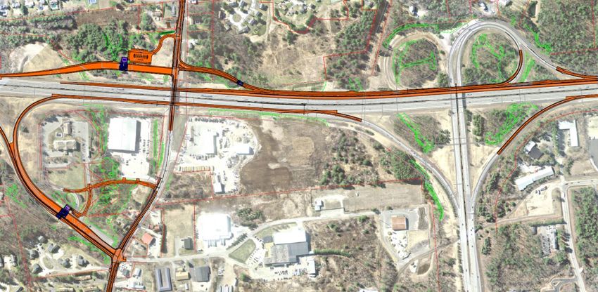
PRELIMINARY DESIGN REPORT

Project Location Plan
January, 2021

Table of Contents
1.0      PROJECT LOCATION PLAN .................................................................................................... 2

2.0      MTA PROJECT RECOMMENDATION FORM ...................................................................... 3

3.0      SUMMARY OF EXPECTED IMPACTS ................................................................................. 12

4.0      SUMMARY OF HIGHWAY ENGINEERING ........................................................................ 13
4.1      PROJECT BACKGROUND ........................................................................................................ 13
4.2      PROJECT DESCRIPTION ............................................................................................................ 14
4.3      HORIZONTAL/VERTICAL ALIGNMENT ................................................................................ 14
4.4      TYPICAL SECTION ..................................................................................................................... 20
4.5      HYDROLOGY, HYDRAULIC AND SCOUR EVALUATION .................................................. 20
4.6      STRUCTURAL ............................................................................................................................ 22
4.7      GEOTECHNICAL ......................................................................................................................... 24
4.8      RIGHT-OF-WAY (ROW) ............................................................................................................. 26
4.9      UTILITIES..................................................................................................................................... 26
4.10     ENVIRONMENTAL .................................................................................................................... 27
4.11     AVOIDANCE AND MINIMIZATION ........................................................................................ 29
4.12     TRAFFIC ....................................................................................................................................... 29
4.13     LIGHTING .................................................................................................................................... 32
4.14     CONSTRUCTION AND MAINTENANCE OF TRAFFIC ......................................................... 33
4.15     CONSTRUCTION SCHEDULE ................................................................................................... 35
4.16     PRELIMINARY ENGINEER’S ESTIMATE ............................................................................... 35

APPENDIX A                 PRELIMINARY PLANS

APPENDIX B                 PRELIMINARY ENGINEER’S ESTIMATE

APPENDIX C                 DRAFT WETLAND DELINEATION REPORT

APPENDIX D                 CONSTRUCTION SCHEDULE & GRAPHIC

APPENDIX E                 PRELIMINARY GEOTECHNICAL REPORT

APPENDIX F                 ROUTE 112 TURNING MOVEMENTS

APPENDIX G                 ADVANCED SIGNING GRAPHICS

APPENDIX H                 NB PLAZA ACCESS OPTIONS GRAPHIC

APPENDIX I                 TRAFFIC VOLUME DIAGRAMS AND TABLES

                                                                                                                                                        1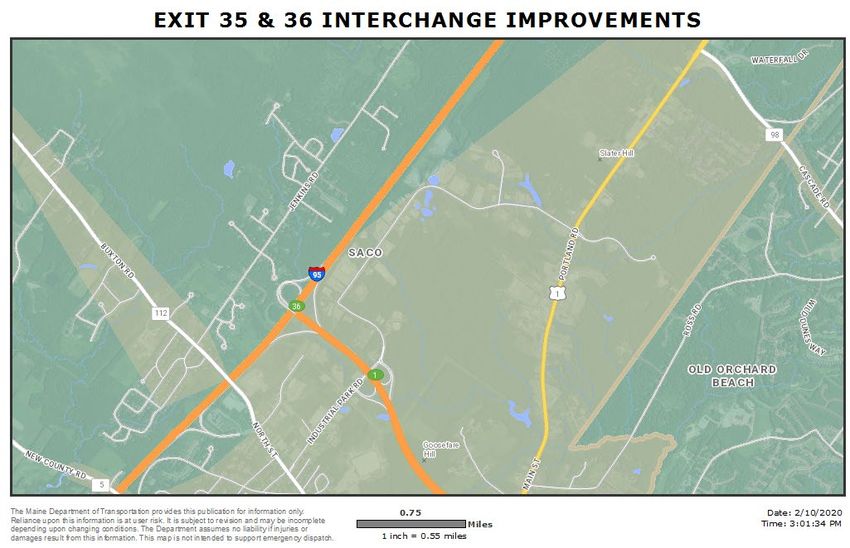
PRELIMINARY DESIGN REPORT

Project Location Plan
January, 2021

1.0          PROJECT LOCATION PLAN

                        Project Limit

        Project Limit                   Project Limit

                                                        2
PRELIMINARY DESIGN REPORT
MTA Project Recommendation Form
January 1, 2021
2.0 MTA PROJECT RECOMMENDATION FORM
City/Town: Saco Route: I-95, State Route 112 MTA Contract No.: 2022.XX
Consultant Project Leader: Lauren Meek, PE
MTA Project Manager: Ralph Norwood, IV, PE, PTOE
Consultant: Stantec Consulting Services Project Length: 2.0 miles Date: June 5, 2020
Project Limits/Description: The project begins on the southern end of the Maine Turnpike
Southbound (I-95) by the Maine State Route 5 overpass (Station 1685+75) and continues 10,625
feet/2.01 miles north (Station 1792+16). On the Maine Turnpike Northbound side, the project
begins on the southern end near the Southbound limit of work (Station 1689+25) and continues
8,275 feet/1.56 miles north to the end of the Exit 36 Northbound On Ramp (Station 1772+00). The
work on Maine State Route 112 begins west of the Turnpike at the Route 112 and Jenkins Road
intersection and continues east for roughly 2,745 feet/0.52 miles to the Route 112 and Industrial
Park Road intersection.
Purpose & Need: The Transportation Study for the Saco Route 112/Exit 36 Area was released in
July 2019. The study was a joint initiative between the City of Saco, Maine Turnpike and the
MaineDOT that produced a series of recommendations to address regional transportation issues
by improving connections to and from the Turnpike. With much input from stakeholders and the
public, the report analyzed several versions of modifying the Exit 36 Interchange area to have a
direct connection with Route 112 which is proposed as Exit 35 an additional interchange (Exit 35)
on both the north- and southbound. Stantec has developed the program for the Exit 36 Interchange
area with a layout for opening year of 2025 and modifications needed when the mainline is
widened with a fourth lane in each direction in 2040.
1. Traffic Data:
Functional AADT
Class (2016)
Maine Turnpike 35,000 (NB)
Principle Arterial Turnpike
I-95 35,000 (SB)
ME-112 Principle Arterial Turnpike 12,300
Posted Speed: Mainline – 70 mph
Plaza Approach/Departure – 10 mph
Exit 35/36 On/Off Ramps – 35 mph
Route 112 - 35 mph
3PRELIMINARY DESIGN REPORT
MTA Project Recommendation Form
January 1, 2021
2. Highway Recommendations:
Disposition of Existing Highway: The Maine Turnpike is a limited access highway
and currently has three travel lanes northbound and three travel lanes southbound.
Maine State Route 112 has one eastbound lane and one westbound lane.
Proposed Recommendations: The proposed work is as follows:
• construction of two new side toll plazas each with an administration building, parking
lot, two cash and one E-ZPass entry lanes, one exit lane, toll booths, canopies,
structural roadway slab, toll equipment, utility services and employee access road;
• construction of Collector-Distributor (C-D) Roadway along southbound I-95 for the
Exit 36 SB on ramp and Exit 35 SB off ramp;
• construction of Exit 35 NB and SB on and off ramps;
• reconfiguration of the Exit 36 NB on ramp to provide a parallel acceleration lane;
• installation of concrete barrier to separate the southbound traffic and the C-D Roadway
traffic;
• installation of lighting for the ramps, plaza area, intersections and parking areas;
• construction of closed and open drainage systems;
• installation of advance guide signing on the Turnpike and Route 112;
• replace the existing Route 112 Park and Ride Lot with a 58-space lot at a location next
to the new Exit 35 SB on ramp;
• installation of a signalized intersection on Route 112 with Exit 35 SB on and off ramps;
• installation of a signalized intersection on Route 112 intersection with Exit 35 NB on
and off ramps and Lund Road;
• construction of a new driveway for Route 112 access for both the Ramada Inn and XL
Sports World complex; and
• reconstruction of sidewalk due to roadway widening along the eastbound side of Route
112 and add sidewalk between the Shell gas station and the Madden Beverage business
on the westbound side.
4PRELIMINARY DESIGN REPORT
MTA Project Recommendation Form
January 1, 2021
Design Criteria:
NB/SB
Maine I-95
Exit 35 Exit 36 Access Rds
Turnpike SB C-D Route 112
Ramps Ramps & Park &
(I-95) Roadway
Ride Lot
12’ 12’
12’; accel/decel accel/decel
Travelway
12’ 14’ ramp lanes; lanes; 11’-12’ 12’
Width
proper 14’ ramp 14’ ramp
proper proper
Shoulder 8’;
12’ (For Future
Width 10’ w/ GR; 8’+ 8’+ 3’-5’ 1’ gravel
Right Lane)
4’ at wall
9-10’ w/
Barrier;
Shoulder
4’ w/o 4’ 4’ 4’ 2’ NA
Width Left
GR/Barrier;
6’ w/ med. GR
Pavement
10” 7.5” 6” 7.5” 6” 4”
Depth
4” ABC-C
Subbase 4” ABC-C 4” ABC-C 4” ABC-C 4” ABC-C 3” ABC-C
8” ASC-G
Depth 18” ASC-G 20” ASC-G 18” ASC-G 20” ASC-G 18” ASC-G
19” Gran. Bor.
Front
6:1 6:1 4:1 4:1 3:1 3:1
Slope
Guardrail
2:1 2:1 2:1 2:1 2:1 2:1
Slope
Back Slope 3:1 3:1 2:1 2:1 2:1 2:1
35 mph
Design 35 mph
70 mph 60 mph Ent./Exit; 35mph 25mph
Speed Ent./Exit
10 mph Plaza
Clear
30’ 30’ 12’ 12’ 12’ 10’
Zone
Applicable Standards and References:
1. MaineDOT Design and Construction Policies
(https://www.maine.gov/mdot/engineering/highway/)
2. State of the Practice and Traffic Control at Toll Plazas: Best Practices: FHWA
http://www.mutcd.fhwa.dot.gov/rpt/tcstoll/pdf/best_practices.pdf
3. A Policy on Geometric Design of Highways and Streets, AASHTO 7th Edition, 2018
5PRELIMINARY DESIGN REPORT
MTA Project Recommendation Form
January 1, 2021
3. ADA Compliance
Pedestrian facilities shall be upgraded to comply with the MaineDOT ADA Compliance
Policy for Construction and Maintenance and the Minimum ADA Requirements for
Pedestrian Facilities Design Guidance.
Select all that apply:
☐ No pedestrian facilities exist on the project and none will be installed.
☐ Existing pedestrian facilities will not be upgraded to ADA compliance based on
project scope.
☒ New pedestrian ADA compliant facilities will be installed where none previously
existed.
☒ Existing pedestrian facilities will be upgraded to ADA compliance unless technically
infeasible.
☒ Pedestrian signals will be installed or upgraded if required.
Summarize:
Currently there is a sidewalk along the eastbound lane of State Route 112 for the extent of
the project. The existing sidewalk does not have ADA compliant pedestrian facilities nor is
there a connection between the stretch of sidewalk along the westbound side of Route 112
and the sidewalk abutting the Shell station. The proposed design will reconstruct the
sidewalk within the limits of the Route 112 work. There will be a five-foot esplanade from
the Access Road to the Ramada Inn, XL Sports and NB Plaza to the eastern limit of work.
Crosswalks are provided at the Exit 35 SB and Exit 35 NB intersections and the major
entrances to the Park & Ride Lot and Access Road to the Ramada Inn, XL Sports, and NB
Plaza. A right turn channelization island for eastbound Route 112 traffic entering the Exit 35
SB Plaza provides a crossing refuge and minimizes the crosswalk length across the SB Plaza
entrance while also accommodating right turning trucks. A pedestrian activated flashing sign
assembly is proposed at the crosswalk at the right turn slip lane. These flashing signs are
located to maximize the sightlines of a vehicle entering the right turn lane.
☒ No technical infeasibility forms are required to be completed at this time.
☐ Technical infeasibility forms have been submitted as indicated in the table below.
Curb Ramp ID/Location Reason Full Compliance Date Approved
Infeasible
None Currently Identified
6PRELIMINARY DESIGN REPORT
MTA Project Recommendation Form
January 1, 2021
Exceptions to Controlling Standards:
Controlling Element Required Proposed Design Date
Standard Approved
Right Shoulder Width for C-D 6-8’ 4’ at Bridge Abutment
Roadway
ADA Exceptions (Yes or No): None Anticipated
Driveway Exceptions (Yes or No): Exceptions anticipated at Sta.
161+20 & 161+73
4. Structural Recommendations:
Clearances: Proposed
Vertical (I-95 SB @ I-195 Bridge) 16.0’ FT
Vertical (I-95 SB @ Rte 112/North St Bridge) 16.0’ FT
Vertical (I-95 NB @ I-195 Bridge) 16.0’ FT
Vertical (I-95 NB @ Rte 112/North St Bridge) 16.0’ FT
Proposed Recommendations:
• Soil Nail Wall at the I-195 SB abutment
• Culvert Extension with Retaining Wall for Goosefare Brook (~Sta. 2750+30, LT.)
• Retaining Barrier at the Route 112 SB abutment
• Replace membrane/wearing surface, upgrade endposts and minor substructure repairs on
the Route 112 bridge
Design Criteria:
Design Loading: Specification:
Structural Slab and Foundation Vehicle Loading - HL-93 AASHTO LRFD bridge Design Specifications,
8th Edition with 2016 Interims
Toll Canopy Roof Live Load - 53 psf ASCE 7-16 Minimum Design Loads and
Associated Criteria for Buildings and other
Structures
Wind Load - 110 ASCE 7-16 Minimum Design Loads for and
MPH Associated Criteria for Buildings and other
Structures
7PRELIMINARY DESIGN REPORT
MTA Project Recommendation Form
January 1, 2021
Snow Load-Ground Snow Load (Pg) - 60 psf ASCE 7-16 Minimum Design Loads and
Associated Criteria for Buildings and other
Structures
Pavement Depth: See Highway Design Criteria.
Design Life: 75-years for new structural components.
5. Available Soils Information:
This site is located in York County, Maine, approximately 11 miles south of Portland, Maine.
A conceptual level evaluation of the subsurface conditions and the potential effect on the
proposed construction has been performed. As part of this evaluation the following information
was reviewed:
• Surficial Geology, Old Orchard Beach Quadrangle, Maine, Open-File No. 99-94, dated
1999.
• Test boring logs and plans from the construction of Route I-195 over the Maine
Turnpike, dated 1981.
• Test boring logs and plans from the North Street bridge replacement project, dated
December 2001
• Geotechnical Engineering Report, Contract 2015.06, EZ Pass Lane Addition, Exit 36
Toll Plaza, Saco, Maine, prepared by Stantec and dated December 18, 2014.
The surficial geology map indicates that a sand deposit is present across the entire project area.
This sand was deposited in marine water during the regression of the ocean from coastal area
after the end of the last glacial period. The sand is commonly underlain by a fine-grained
cohesive silty clay formation deposited in deeper and calm marine water during the marine
submergence of the coastal zone. The silty clay deposit is commonly known as the
Presumpscot Formation and typically consists of a relatively thin stiff crust layer underlain by
a thick soft layer.
Based on the boring logs from past transportation projects in the area, the geology is consistent
with the geologic map and the coastal area of Maine. The general subsurface conditions
encountered in the test borings are summarized in the table below. The table does not include
the thickness of existing roadway embankment fills which are present near the existing bridge
structures. The embankment fills are generally 15 to 20 feet in height.
6. Project Schedule:
Construction Timeline: Approximate 30-month construction duration
Advertisement: Anticipated by 2023
8PRELIMINARY DESIGN REPORT
MTA Project Recommendation Form
January 1, 2021
7. Maintenance of Traffic:
The construction of the new toll plazas at both north- and southbound Exit 35 will be open and
operational before the work on north- and southbound Exit 36 occurs.
Phase 1A will be construction of the Route 112 Access Road for the Ramada Inn as well as
beginning construction of the Exit 35 SB ramps and plaza area. Phase 1B will be construction
of the Exit 35 Southbound Ramps as well as all the Southbound Plaza work including
construction and testing.
Phase 1B will also consist of all the Route 112 roadway and intersection improvements. The
first part of the Collector-Distributor Road by Exit 35 will be constructed during Phase 1B. All
the Exit 35 Northbound Ramp construction and testing will take place during Phase 1B.
Phase 2 will focus on construction of the Exit 36 ramps and completion of the C-D Roadway.
Phase 3 will consist primarily of final paving and project clean up.
8. Right of Way Impacts:
Right of way impacts were avoided and minimized during the 2019 Saco Route 112/Exit 36
Area Transportation study for this project. The number of interchange alternatives were
narrowed down to two key viable configurations. An alternative to extend I-195 westerly to
Route 112 along with a complete reconfiguration of Exit 36 was found to provide several
positive improvements, including reducing traffic congestion on Route 112. However, the
property impacts, including the need for full acquisitions, were substantial. The current Exit
35-36 configuration was selected due to its ability to improve Turnpike access with relatively
minor property impacts and no full acquisitions. In addition, property impacts were reduced
further during preliminary design. In particular, the Route 112/Exit 35 NB ramps intersection
analysis was reevaluated in an effort to reduce the width of improvements and impacts along
Route 112. Through collaboration with the study team, minor adjustments were made to the
traffic model to better reflect actual conditions. The adjustments led to reducing the westbound
double left turn lane to a single left turn lane, resulting in reduced property impacts to several
properties.
9. Public Process:
The following public meetings at Saco City Hall were held as part of the 2019 Saco Route
112/Exit 36 Area Transportation Study:
• June 14, 2018 “blank page” meeting to hear the public’s concerns
• September 27, 2018 potential solutions presentation and feedback
• February 13, 2019 presentation of final array of alternatives. The Study Team
received positive feedback on the current Exit 35-36 alternative.
9PRELIMINARY DESIGN REPORT
MTA Project Recommendation Form
January 1, 2021
A more detail description of the meetings and public process is included in the study.
On October 6, 2020, the City of Saco presented the draft preliminary plans of Route 112 to the
Traffic Safety Committee.
Environmental Permitting Public Notice of Intent
Due to the likely levels of State and Federal permitting there will be a requirement for
additional public notice of intent to file the permit applications. This includes notice to abutters,
public notification in a local newspaper, a public hearing, and the permit applications to be
available at the municipal office(s), MDEP and USACE local offices.
10. Anticipated Permit Level
Maine Department of Environmental Protection: Individual Permit
*US Army Corps of Engineers: Individual Permit
NPDES: MPDES-GP
NOI: Yes
*Due to proposed alteration of protected natural resources and alteration of areas adjacent to
protected natural resource, permit approval will be required by Maine Department of
Environmental Protection (MeDEP) and US Army Corps of Engineers (ACOE). Project plans
are not fully designed so currently the amount and types of resource alteration are not fully
assessed. Therefore local, State, and Federal permitting requirements are not finalized.
Confirmation of proposed permitting thresholds will be determined by the final design
alterations and through a discussion with MeDEP and Corps at the pre-application meeting.
Construction methods will likely be required where working in or close to resources to
demonstrate avoidance of unnecessary and non-permitted alteration of regulated resources.
Proposed disturbance area does not currently exceed thresholds triggering the Site Location of
Development Law.
The proposed disturbance and construction activity are one acre or more of disturbed area and
will require coverage under the Construction General Permit (CGP) requirements; therefore, a
Notice of Intent (NOI) will be required.
This project will comply with the current Memorandum of Agreement (MOA) between
MeDEP and MTA (June 2017). Section 3 of the MOA states that all projects shall comply with
the requirements of MeDEP Chapters 500 and 502. Specific Provisions:
A. Basic Standards: This project will meet the Basic Standards described in Section 4(B) of
Chapter 500, through the implementation of the MeDEP Best Management Practices for
Erosion and Sediment Control.
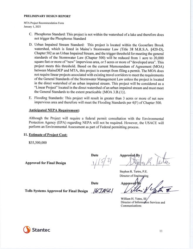
B. General Standards: This project is located within the Goosefare Brook watershed, which is
listed in Maine’s Stormwater Law (Title 38 M.R.S.A. §420-D), Chapter 502 as an Urban
Impaired Stream, and will meet the General Standards to the extent practicable.
10PRELIMINARY DESIGN REPORT
Summary of Expected Impacts
January 1, 2021
3.0 SUMMARY OF EXPECTED IMPACTS
RIGHT OF WAY –
Number of: Property Owners = 14
Buildings To Be Taken = 0
Type of Acquisitions: Fee Simple Easement
Grading Temporary Road
HISTORICAL/ARCHEOLOGICAL – Outreach to the Maine Historic Preservation
Commission (MHPC) and State Tribes has not been initiated.
COAST GUARD PERMIT? No FAA PERMIT? No
ENVIRONMENTAL –
Instream Work Window? Yes From July 15 To September 30
Wetlands: The preliminary combined permanent and temporary wetland impact total is
approximately 191,831 SF (4.40 Ac.)
Freshwater Area = 0 SF Coastal Area = 0 SF
Mitigation Required: Yes
Dredged Spoils Testing Required: No
Stream Diversion: Yes; 150 feet each bank
Expected Permit and NEPA Level:
MDEP: Individual NRPA Permit ACOE: Individual Permit LUPC: No
NPDES: CGP (Construction General Permit) NEPA: No
Summary of Avoidance and Minimization: Project plans were modified in several ways to avoid
wetland and stream alterations. Where avoidance of these natural resources was not possible the
plans were further modified to minimize resource alterations to achieve the least environmentally
damaging practicable alternative (LEDPA) for the project design. To minimize wetland impacts
in areas of high fill, steep 2H:1V slopes with guardrail are proposed rather than the standard 6H:1V
slopes. The Exit 35 SB Park & Ride lot is sited so access to the plaza admin building is provided
but minimizes the impacts to wetlands to the west. The relocated access road for the hotel’s Route
112 entrance aligns closely to the parking lot of the gym to minimize the embankment footprint
through the wetlands.
12PRELIMINARY DESIGN REPORT
Summary of Highway Engineering
January 1, 2021
4.0 SUMMARY OF HIGHWAY ENGINEERING
4.1 PROJECT BACKGROUND
A transportation study for the Saco Route 112/Exit 36 Area was released in July 2019. The study
was a joint initiative between the City of Saco, Maine Turnpike and the MaineDOT that produced
a series of recommendations to address regional transportation issues by improving connections
to and from the Turnpike. The predominant recommendation involved expanding Exit 36 to
include Turnpike access to Route 112. Specifically, the improvements consist of providing
Turnpike access to Route 112 via a Collector-Distributor (C-D) roadway on the southbound
Turnpike mainline and an auxiliary lane between Exit 36 and Route 112 on the northbound
Turnpike mainline. The improvements to the northbound Turnpike will increase the weave length
between the Route 112 on ramp (the old Exit 5 on ramp) and the offramp to I-195 from an existing
870’ to an acceptable length of 2,150 feet. Access to the Turnpike will be provided at Lund Road
(with signals) and at a new signalized intersection west of the Turnpike.
The project also includes building a toll plaza at Exit 35 NB on and off ramp with three entry lanes
(two cash and one E-ZPass) and one exit lane. A toll plaza will be constructed at the Exit 35 SB
on ramp with three entry lanes (two cash and one E-ZPass). Both toll plaza will have an admin
building, associated parking and an access road For Exit 35 SB off ramp, a toll exit gantry will be
constructed. A park and ride lot is proposed to replace the existing lot at the Ramada Inn entrance
that needs to be closed for the new Turnpike northbound ramps. The proposed location of the 58-
space lot is next to the Exit 35 SB admin building with access from Route 112.
The following changes were made in collaboration with the MTA after the 10% design submission:
• The Route 112 westbound double left turn lane to the northbound on ramp was reduced to
a single left turn lane.
• A westbound left turn lane to Hillview Avenue is proposed. The layout for this addition
will be provided at a later date after survey is completed.
• The 10% option for replacing the existing park and ride lot on Ramada Inn property was
dropped in favor of the current location next to the Exit 35 SB on ramp. The current
location is owned by the MTA and the topography is more favorable for the design. Design
will incorporate a landscaped berm and fencing along the abutter’s property line.
• Improvements to the Exit 36 NB on ramp to provide a parallel acceleration lane.
• The design was modified to reduce the limits of work and associated impacts for the Exit
36 SB off ramp construction.
13PRELIMINARY DESIGN REPORT
Summary of Highway Engineering
January 1, 2021
4.2 PROJECT DESCRIPTION
The proposed construction scope includes the construction of:
• construction of two new side toll plazas each with an administration building, parking lot,
two cash and one E-ZPass entry lanes, one exit lane, toll booths, canopies, structural
roadway slab, toll equipment, utility services and employee access road;
• construction of Collector-Distributor (C-D) Roadway along southbound I-95 for the Exit
36 SB on ramp and Exit 35 SB off ramp;
• construction of Exit 35 NB and SB on and off ramps;
• reconfiguration of the Exit 36 NB on ramp to provide a parallel acceleration lane;
• installation of concrete barrier to separate the southbound traffic and the C-D Roadway
traffic;
• installation of lighting for the ramps, plaza area, intersections and parking areas;
• construction of closed and open drainage systems;
• installation of advance guide signing on the Turnpike and Route 112;
• replace the existing Route 112 Park and Ride Lot with a 58-space lot at a location next to
the new Exit 35 SB on ramp;
• installation of a signalized intersection on Route 112 with Exit 35 SB on and off ramps;
• installation of a signalized intersection on Route 112 intersection with Exit 35 NB on and
off ramps and Lund Road;
• construction of a new driveway for Route 112 access for both the Ramada Inn and XL
Sports World complex; and
• reconstruction of sidewalk due to roadway widening along the eastbound side of Route 112
and add sidewalk between the Shell gas station and the Madden Beverage business on the
westbound side.
Careful consideration has been made to avoid and minimize direct and indirect impacts to the
wetlands.
4.3 HORIZONTAL/VERTICAL ALIGNMENT
Northbound Exit 35 Off Ramp
Existing
The existing off ramp is a tapered exit ramp with a 285’ painted gore and includes a
relatively tight 400’ radius curve where it turns away from the Turnpike. Currently the
ramp is connected to the Ramada Inn parking lot and does not provide direct access to
Route 112.
14PRELIMINARY DESIGN REPORT
Summary of Highway Engineering
January 1, 2021
Proposed
The project replaces the existing tapered exit with a parallel exit lane. The proposed
alignment turns away from the Turnpike through a 1,500’/750’ compound curve. The
compound curves are followed by a 219’ tangent that connects to a 750’ radius curve that
turns the alignment toward Route 112. Although the proposed alignment does completely
avoid the wetlands that the current alignment does, the proposed horizontal alignment
provides a much more gradual transition to the toll plaza area.
Northbound Exit 35 On Ramp
Existing
The existing on ramp is a tapered entrance ramp with a 500’ painted gore that ties into the
auxiliary lane leading to the Exit 36 off ramp. The auxiliary lane provides approximately
870’ for weaving maneuvers between entering and exiting traffic. Currently, the ramp is
connected to the Ramada Inn parking lot and does not provide direct access to the Turnpike
from Route 112.
Proposed
The proposed horizontal alignment follows the existing horizontal alignment for most of
the ramp except where it matches into mainline auxiliary lane through a flatter 680’ radius
curve. The result is a parallel single lane entrance with a 195’ painted gore that has been
moved roughly 825 feet to the south. Combined with revision to the northbound Exit 36
off ramp revision described below, the length of the auxiliary lane is increased by 1280’.
The proposed auxiliary lane is 2,150’ long, exceeding the 2000’ minimum length
recommended by AASHTO.
The project also modifies the ramp to accommodate a three-lane side plaza located
approximately 550’ from its intersection with Route 112. Similar to the southbound plaza,
the departure tapers from 51’ to 14’ wide in 901’ (24:1 taper).
The vertical alignment was developed to provide a high point at the the proposed
northbound toll plaza and to mimic the existing ramp grade as much as possible. The last
400’ of the profile lowers the existing ramp by 2’ to 3’ in order to tie into the mainline
further south than existing.
Northbound Exit 36 Off Ramp
Existing
The existing Exit 36 off ramp is a tapered exit ramp with a 565’ painted gore.
Proposed
The project will replace the tapered exit with a parallel exit ramp that ties into the Turnpike
auxiliary lane through an 1800’ radius curve. The revised alignment moves the painted
15PRELIMINARY DESIGN REPORT
Summary of Highway Engineering
January 1, 2021
gore approximately 455’ to the north. Combined with the northbound Exit 35 on ramp
revision described below, the length of the auxiliary lane is increased by 1280’.
There is no change to the vertical alignment.
Northbound Exit 36 On Ramp
Existing
The existing Exit 36 on ramp is a direct connection to the Turnpike with a tapered single
lane entrance ramp.
Proposed
The project will replace the tapered entrance with a parallel single lane entrance ramp that
has a 1300’ acceleration lane and a 300’ taper that matches into the Turnpike. The 975’
radius is much flatter than the existing curvature thus creates a much smoother transition
into the Turnpike. The design speed is 35 MPH.
There is no change to the vertical alignment.
Southbound Collector-Distributor Roadway
Existing
None
Proposed
The Collector-Distributor (C-D) Roadway baseline runs parallel to the Main Turnpike and
serves the Exit 36 SB off and on ramps and the Exit 35 SB off ramp. The baseline is offset
a distance of 77’ to allow for a future fourth southbound lane with an adjacent 10’ shoulder.
Until the fourth lane is warranted, a 22’ wide shoulder will be striped as the outside
shoulder for the existing three-lane section. The adjacent 10’ shoulder will be unused until
the fourth mainline travel lane is needed.
As recommended by AASHTO, the design speed for the C-D Roadway was set at 60 MPH,
10 MPH under the mainline design speed. The lower speed roadway with its 1,950’ (1,650’
required) auxiliary lane will provide for safer weaving maneuvers between entering traffic
from the I-195 on ramp and exiting off ramp traffic to Route 112.
The C-D Roadway is transitioned back into the mainline by a gradual reverse curve (5000’
and 8100’ respectively) which leads to a parallel on ramp that provides a 500’ gap
acceptance length and a 300’ tie-in taper.
The C-D Roadway vertical alignment is a spline profile developed from the mainline
elevations and cross slopes to accommodate the two roadways’ opposing cross slopes. The
16PRELIMINARY DESIGN REPORT
Summary of Highway Engineering
January 1, 2021
spline angle points were developed to not exceed an algebraic difference of grade 0.6%
and are generally less than 0.2%.
Southbound Exit 36 Off Ramp
Existing
The existing Exit 36 off ramp is a semidirect connection to I-195 with a tapered single lane
exit from the Turnpike. This ramp has been identified as a near High Crash Location
(HCL) with a Critical Rate Factor of 0.96. The data does not point to a particular reason
for the crashes, but it is surmised that the relatively short tapered exit lane is a contributing
factor.
Proposed
The proposed horizontal geometry for the southbound Exit 36 off ramp has a flat radius
allowing for a smooth transition from the CD roadway speed to the ramp speed. The
proposed parallel single lane exit ramp with a 1500’ auxiliary lane and a 300’ taper will
improve safety. The ramp design speed is 35 MPH.
The proposed vertical alignment is a spline profile developed from the mainline cross
slopes and ties into the existing ramp in approximately 225’.
Southbound Exit 36 On Ramp
Existing
The existing southbound Exit 36 on ramp is a 30 MPH cloverleaf loop ramp with a parallel
single lane entrance. This loop ramp does not meet current design criteria for design speed
in relation to the mainline design speed of 70 MPH.
Proposed
The existing ramp entrance geometry will be modified to connect to the proposed C-D
Roadway. The point of compound curvature was shifted slightly to provide a 231’ entrance
radius. However, the entrance to the slower C-D Roadway will be improved and meet the
design criteria for the ramp’s design speed in relation to the C-D Roadway design speed.
The proposed vertical alignment matches the existing alignment with minor adjustments to
tie into the new C-D Roadway.
Southbound Exit 35 Off Ramp
Existing
None Existing
Proposed
17PRELIMINARY DESIGN REPORT
Summary of Highway Engineering
January 1, 2021
The exit geometry for proposed Exit 35 off ramp from the CD roadway consists of a 750’
radii reverse curve and 200’ perpendicular approach to Route 112. The approach provides
a 400’ right turn lane with the last 70’ being channelized. The ramp design speed is 35
MPH.
The southbound Exit 35 off ramp profile rises at 5% from a 300’ sag vertical curve at the
CD roadway. The profile is terminated at Route 112 by a 105’ vertical curve that provides
an approximate 2.7%, 50’ long approach.
Southbound Exit 35 On Ramp
Existing
None Existing
Proposed
The proposed southbound Exit 35 on ramp layout was developed to accommodate a new
three lane side plaza and provide 1500’ from the plaza to the end of the painted gore with
the mainline. The ramp was designed as a parallel single lane entrance that has a 1300’
acceleration lane and a 300’ taper that matches into the Turnpike. There is a 1051’/4500’
radii reverse curve directly after the plaza that ties into the parallel acceleration lane. After
the plaza there is an 878’ departure taper (approximately 22:1) to transition the 51’ wide
plaza area to a 12’ lane. The design speed is 35 MPH.
The vertical alignment was developed to provide a high point at the proposed southbound
toll plaza and to minimize slopes (2% max) approaching the plaza. The profile was also
developed in conjunction with the design of the adjacent proposed 58 space park and ride
lot. A 5.0% downgrade brings the ramp to the mainline elevation.
Southbound Admin Building and Park and Ride Lot Access Road
Existing
None Existing
Proposed
The southbound administration building and park and ride lot access road will be all new
construction that ties into Route 112. The alignment forms a new unsignalized intersection
with Route 112 at the westerly extent of the Maine Turnpike property. The intersection is
located 250’ from the signalized on ramp intersection. The access road follows a 75’/100’
radii reverse curve to place the parking lot adjacent to the southbound on ramp. The
alignment accommodates a Zoom Turnpike Express bus.
Northbound Admin Building and Ramada Inn/XL Sports World Access Road
Existing
18PRELIMINARY DESIGN REPORT
Summary of Highway Engineering
January 1, 2021
None Existing
Proposed
The new road will provide Route 112 access to the Toll Plaza administration building and
replace the existing access for the Ramada Inn and the XL Sports World complex. The
road creates a new unsignalized intersection approximately 650’ from the signalized
northbound ramps intersection and beyond its anticipated queue length.
The new road connects directly to the Ramada Inn’s front access road and intersects its
back access road as well as the new plaza admin building access. The alignment includes
two driveways for the XL Sports Complex. The Ramada Inn will no longer have direct
access to the northbound ramps.
The new Ramada Inn access road alignment consists of a 300’/750’ radii reverse curve and
400’ radius curve separated by a 212’ tangent. Its approach to Route 112 ends in a left lane
with an adjacent a 75’ right turn lane. The administration building access road is 280’ long
and consists of a 325’/40’ radii compound curve. The 40’ curve can accommodate an SU
design vehicle.
An alternative layout is provided in Appendix H. This maintains the same alignment for
the Ramada Inn. The plaza parking follows the existing roadway for the hotel’s Turnpike
access.
Route 112
The Route 112 widening improvements are designed for 35 MPH and occur in two
locations. The westerly location begins at the Hillview Ave. Extension intersection and
will match into existing conditions or improvements from the City of Saco’s Jenkins Drive
Intersection project depending on the timing of the project. The MTA project extends from
Hillview Ave. Extension 200’ east of the Route 112 bridge over the Maine Turnpike. The
easterly location begins at the former Saco Public Works facility and extends 780’ west of
the Industrial Park Road Intersection. The baseline for both of these locations follows the
existing roadway centerline with the westerly location entirely on tangent and the easterly
location consisting of two 1,100’ radius curves separated by a 242’ tangent.
Route 112 is widened at both locations to develop right and left turn lanes at the various
intersections. The widenings for the development of the right turn lanes to the Turnpike
NB and SB On Ramps are developed with approximate 9:1 tapers (100 feet). The left turn
lane to Hillview Ave. develops out of the approaching two-way center turn that begins at
the park and ride lot entrance. The development of the left turn lanes into the Park & Ride
Lot Entrance and NB On Ramp also have approximate 9:1 tapers (100 feet). The
development of the left turn lanes for the SB On Ramp and Hotel/Gym Access Road are
developed after the thru lane has completed the shift outward and a 50’ length is provided
as allowed by AASHTO Section 9.7.2.3. This maximizes the left turn lane queue storage.
19PRELIMINARY DESIGN REPORT
Summary of Highway Engineering
January 1, 2021
The proposed vertical alignment matches the existing grade to provide for a variable depth
mill and overlay.
4.4 TYPICAL SECTION
The proposed typical sections are shown in the preliminary plans in Appendix A. Travel lanes on
the Turnpike mainline are 12’ in width and ramp travel lanes are 14’ in width with both mainline
and ramps having 4’ wide left shoulders. The mainline right shoulders are 12’ in width and ramp
right shoulders are 8’ in width. A Collector-Distributor roadway is proposed for the southbound
mainline which is physically separated by concrete median barrier. This roadway will have two
12’ lanes, a 4’ wide left shoulder and an 8’ wide right shoulder, with the exception of the right
shoulder between the Exit 36 SB On Ramp and the I-195 bridge underpass which has a width of
4’. This Collector-Distributor roadway barrier is proposed to be located for the future mainline
fourth lane and therefore the right shoulder for the mainline adjacent to the barrier will have an
additional 12’ in width. Through and turning lanes on Route 112 are proposed to be 11’ in width
with 3.5’ to 5’ wide shoulders. The Route 112 sidewalk is 5.5’ wide.
The toll plazas for both NB and SB On-ramps are proposed to have two cash lanes and one E-
ZPass only lane, similar to the configuration at the new Exit 63 SB On-ramp. The two lanes that
are bordered by booth islands will be 12’ wide. The right most lanes will be 11’ wide with an
adjacent 8’ shoulder.
The Design Criteria for the project is presented in Section 1. The existing Route 112 Turnpike
underpass bridge has a curb-to-curb width of 40’. With three 11-foot lanes, the right shoulder width
on Route 112 is proposed to be 3.5’ wide. This section of Route 112 is designated as a bike route
by the City of Saco and as such would need a 5’ shoulder to accommodate a bike lane; however,
MaineDOT standards note that for a Highway Corridor Priority 2 roadway such as Route 112, the
shoulder width should be 3’ to 5’. MaineDOT has reviewed and determined that a design exception
is not needed for this location. It is noted that the shoulders east of Lund Road are also less than
5’ wide.
4.5 HYDROLOGY, HYDRAULIC AND SCOUR EVALUATION
There are ten (10) existing cross culverts under the Turnpike mainline. The first three located
south of Route 112 flow to the east to the Saco River. The other seven flow to the west to the
Goosefare Brook. A preliminary hydrologic analysis of the drainage areas was performed to
determine if the culverts are adequately sized for the existing and proposed conditions. For a 50-
year storm event, eight of ten were found to be adequate. Overflow drainage from the culvert at
Sta. 1694+65 will go to the wetlands along the Exit 35 NB Off Ramp. Overflow drainage from
the culvert at Sta. 1757+18 continues directly to the Goosefare Brook before it goes under the
Exit 36 SB Off Ramp.
20PRELIMINARY DESIGN REPORT
Summary of Highway Engineering
January 1, 2021
50-Year Storm Event Drainage Evaluation
Culvert Number
Existing Proposed
Diameter
Station
Type
(in)
Percent of Percent of
Adequate Required Adequate Required
Mannings Mannings
Size? Dia. Size? Dia.
Capacity Capacity
1 18 RCP 1694+65 Yes Yes
2 48 RCP 1699+45 Yes Yes
3 36 RCP 1712+07 Yes Yes
4 36 RCP 1731+70 Yes Yes
5 54 RCP 1739+50 Yes Yes
6 18 RCP 1757+18 No* 254% 48 No* 322% 60
7 18 RCP 1764+92 Yes Yes
8 36 RCP 1770+46 Yes Yes
9 48 RCP 1778+06 Yes Yes
10 48 RCP 1783+18 Yes Yes
* Overflow can bypass directly to Goosefare Brook
The roadway drainage swales along this section of the Turnpike are fairly flat and some are located
within wetlands. The design of the open drainage systems will have to recognize the existing
drainage patterns of the wetlands and the need to have positive drainage in swales and drainage
the roadway subgrade.
The design includes three locations for closed drainage systems:
1. A proposed closed drainage system associated with the 3,640 feet of median barrier along
the C-D Roadway has been designed for a 10-year storm event. The layout has six RCP
outlets to the western open roadside swales.
2. A closed drainage system is along the curbed Route 112 roadway west of the Turnpike.
The drainage system has proposed and existing underdrain and catch basins from the
Hillview Ave Extension to the Route 112 bridge. The system utilizes the existing outlet
pipe located at Sta. 144+20, right that is in an existing drainage easement.
3. The third location for a closed drainage system is along the curbed Route 112 roadway east
of the Turnpike and installs underdrain and catch basins for the roadway widening. The
drainage system between Sta. 157+30 and the NB Exit 35 intersection connects to the
existing outlet at Sta. 156+50, left. The proposed drainage from the NB Exit 35 intersection
east to the limit of work connects to the drainage system that outlets to the north at Sta.
170+00.
The project includes extending an 84” RCP carrying the Goosefare Brook by 23 feet. This will
require the relocation of the stream for approximately 125 feet. Final design will include a peak-
flow hydraulic analysis and modeling to evaluate the base flood elevation for the FEMA flood
plain.
21PRELIMINARY DESIGN REPORT
Summary of Highway Engineering
January 1, 2021
4.6 STRUCTURAL
The construction will include one new toll plaza with entry lanes for the Exit 35 SB On Ramp, one
new toll plaza with entry and exit lanes for the Exit 35 NB On and Off Ramp, one new toll gantry
for the Exit 35 SB Off ramp exit lane, and one administration building for each of the toll plazas.
The cash lanes will include new toll booths, utility pits, concrete islands, and a structural steel
canopy. The layout constraints, foundations, plaza details, and phasing considerations are outlined
for each plaza component below. In addition to the toll plaza construction, an extended 84” RCP
will require a prefabricated concrete modular gravity retaining wall, a soil nail wall will be
constructed in front of the I-195 western abutment, and a retaining barrier will be constructed at
the bottom of the Route 112 western abutment slope protection.
4.6.1 Exit 35 Northbound Entry and Exit Plaza
The Northbound (NB) administration building is located south of the existing Park and
Ride lot, directly adjacent to the Exit 35 NB Ramps. The NB and SB cash lanes have the
same lane geometry, toll booth geometry, and entry/approach slab widths. The concrete
island geometry (bumpers, nose, etc.) are the same.
4.6.2 Exit 35 Southbound Entry Plaza
The Southbound (SB) administration building is located directly adjacent to the Exit 35 SB
On Ramp. The NB and SB cash lanes have the same lane geometry, toll booth geometry,
and entry/approach slab widths. The concrete island geometry (bumpers, nose, etc.) are the
same.
4.6.3 Exit 35 Southbound Exit Gantry
The Exit 35 Southbound off ramp requires a gantry for tolling operations. This monotube
structure and the concrete roadway slab underneath will be founded on piles. Due to the
sensitive nature of tolling equipment, settlement will be minimized. Approach slabs will
be constructed before and after the roadway slab.
4.6.4 Goosefare Brook Culvert Extension
The Goosefare Brook culvert extension is located on the SB collector at STA 2750+29.00
LT. The extension is an 84” reinforced concrete pipe (RCP) attached to the existing 84”
RCP with a reinforced concrete collar. To minimize the impacts to Goosefare Brook, a 65’-
0” long prefabricated concrete modular gravity (PCMG) retaining wall is located along the
headwall of the culvert extension. Reinforcing in the concrete collar and PCMG wall are
epoxy-coated. There will be regrading of the sideslopes along the ramp and the inlet of the
Goosefare Brook in the immediate culvert extension area as the brook flow is skewed to
the existing culvert. Special fill will be used in the regrading area at the inlet of the culvert
extension. The use of a cofferdam is anticipated to complete the culvert extension work.
22PRELIMINARY DESIGN REPORT
Summary of Highway Engineering
January 1, 2021
4.6.5 I-195 Soil Nail Wall
The location of the proposed southbound collector-distributor roadway encroaches upon
the existing west abutment slope protection below the I-195 bridge spanning over the
Turnpike. Due to limited overhead clearance the construction of a soil nail wall between
SB collector STA 2743+25 to STA 2745+95 is proposed to provide the necessary grade
separation for the roadway. The existing west stub abutment of the I-195 bridge is founded
on spread footings and may require supplemental tie-backs for stability purposes,
depending on the final design of the soil nail retaining wall. A cast-in-place single-slope
roadway barrier is to be positively attached to the roadway face of the soil nail wall.
4.6.6 Route 112 Barrier
The existing concrete slope paving at the Route 112 bridge is impacted by the SB Collector.
To prevent sloughing of the concrete slope paving and undermining the abutment slope, an
Earth Retaining Barrier is proposed. The Earth Retaining Barrier will have epoxy coated
reinforcing and transition to guardrail with a modified reinforced concrete transition
barrier. The slope paving is removed to an existing joint to accommodate the widened
roadway and allow for a new reinforced concrete drainage swale behind the Earth
Retaining Barrier.
4.6.7 Route 112 Bridge
The 2020 annual inspection report rated the Route 112 bridge as “Satisfactory” for the
wearing surface and “Good” for the underside of the deck and barrier. However, the MTA
would like to take the opportunity to address maintenance issues to take advantage of the
MOT that will be in place for the Route 112 work and given the growing traffic volumes.
This will prolong the life of the deck.
Design will replace membrane/wearing surface and provide a deck repair contingency,
upgrade the guardrail transition and endposts, and address minor repairs such as concrete
spalls on the barrier and wing, re-rub the pier columns, repair mortar in granite curbing and
repair/replace barrier parrafin joints. The deck joint scope is still to be finalized. Cleaning
out/repairing berm erosion at NE asphalt curb cut/riprap downspout and curb termination
area will also be included.
The existing bridge has two 12’ travel lanes with 8’ shoulders and a sidewalk on the
southern side. Three 11’ travel lanes with 3.5’ shoulders are proposed which will leave the
crown in the center of the left turn lane. Shifting the crown would involve reworking the
bridge joint and have challenges with maintaining appropriate curb reveals on the sidewalk
and barrier and cross slopes. This additional work was considered not to be prudent to the
project.
23PRELIMINARY DESIGN REPORT
Summary of Highway Engineering
January 1, 2021
4.7 GEOTECHNICAL
As part of the geotechnical evaluation, 7 test borings have been drilled at the sites of both proposed
toll facilities and along the Exit 36 SB Ramps. A conceptual level evaluation of the subsurface
conditions and the potential effect on the proposed construction has been performed. As part of
this evaluation the following information was reviewed:
• Surficial Geology, Old Orchard Beach Quadrangle, Maine, Open-File No. 99-94, dated
1999.
• Test boring logs and plans from the construction of Route I-195 over the Maine Turnpike,
dated 1981.
• Test boring logs and plans from the North Street bridge replacement project, dated
December 2001
• Geotechnical Engineering Report, Contract 2015.06, EZ Pass Lane Addition, Exit 36 Toll
Plaza, Saco, Maine, prepared by Stantec and dated December 18, 2014.
The surficial geology map indicates that a sand deposit is present across the entire project area.
This sand was deposited in marine water during the regression of the ocean from coastal area after
the end of the last glacial period. The sand is commonly underlain by a fine-grained cohesive silty
clay formation deposited in deeper and calm marine water during the marine submergence of the
coastal zone. The silty clay deposit is commonly known as the Presumpscot Formation and
typically consists of a relatively thin stiff crust layer underlain by a thick soft layer.
Based on the boring logs from past transportation projects in the area, the geology is consistent
with the geologic map and the coastal area of Maine. The general subsurface conditions
encountered in the test borings are summarized in the table below. The table does not include the
thickness of existing roadway embankment fills which are present near the existing bridge
structures. The embankment fills are generally 15 to 20 feet in height.
Area General Subsurface Conditions Strength of Clay (psf)
I-195 Bridge • 25 feet of medium silty sand Undrained shear strength ranged
• 120 to 135 feet of medium stiff to stiff, from 800 to 1600 psf increasing
gray, silty clay with depth. No identifiable crust
• 10 to 25 feet of medium dense silty layer.
sand
• Bedrock is 172 to 184 feet below the
mainline turnpike grade
24PRELIMINARY DESIGN REPORT
Summary of Highway Engineering
January 1, 2021
North Street • 10 to 15 feet of hard to soft, brown to Clay is very thin and
Bridge gray, silty clay predominately medium stiff to
• 5 to 10 feet of dense glacial till hard. Shear strength test not
• Bedrock is 15 to 25 feet below the available.
mainline turnpike grade
Exit 36 Toll • 5 to 10 feet of medium dense sand Crust was present in two of the
Plaza • 56 to 139 feet soft to very soft, gray, three borings and was less than 10
silty clay feet thick. Undrained shear
• 0 to 10 feet of dense glacial till strength of the soft clay ranged
• Bedrock is 56 to greater than 176 feet from 300 to 500 psf.
below the I-195 grade
Based upon a review of the available subsurface information, the conditions are highly variable
across the project area. Conceptual level comments for the various portions of the project are
provided below.
• I-195 Ramp Area
This area is underlain by a significant thickness of clay. The strength of the clay is expected to
range from very soft to stiff. Large embankment fills constructed on virgin ground are expected
to produce significant settlement due to consolidation of the clay. Embankment construction
will likely require preloading to allow the settlement to occur prior to constructing the final
pavement section. If the duration of the preloading is more than the project schedule will allow,
then wick drains may be required to shorten the preload duration. Lightweight fill may also be
an option for embankment construction. Large embankment fills over the thick clay may also
have slope stability issues which may require the use of geosynthetics to reinforce the
embankment slopes. Embankment widening with only minor grade change may not require
preloading or other special construction techniques.
North Street Bridge Area
In the area of North Street bridge, the clay is relatively thin and stiff and the bedrock is
relatively shallow. Proposed embankment fills in this area may not need special construction
techniques such as over excavation, lightweight fill, preloading and wick drains. However, the
proposed ramps are expected to extend several hundred feet beyond the location of the historic
bridge borings and the subsurface conditions may change significantly with distance.
• Lund Road Ramp Area
Surface information for the area was not available. Based on the surficial geology map this
area will have a sand deposit underlain by a clay deposit. Given the highly variable soil
conditions between the I-195 Ramp and North Street area it is difficult to anticipate the
subsurface conditions in this area. Small embankment fills and small lightweight tolling
structures may not induce large settlements in this area. It may be possible to found lightweight
25PRELIMINARY DESIGN REPORT
Summary of Highway Engineering
January 1, 2021
structures on conventional spread footings. Consideration will need to be given to tolling
equipment which is sensitive to settlement.
• Mainline Widening
The subsurface conditions will vary significantly along the mainline. The proposed widening
along the east and west sides of the mainline may cause excessive settlement if the
embankment fills exceed more than approximately 5 feet and extend into areas significantly
beyond the current roadway embankment. Small grade raises that are close to the existing
roadway embankment will likely induce relatively minor settlement that will be tolerable.
Stability of the embankment side slopes are not expected to be an issue along the mainline
provided the slopes are less than 3 Horizontal to 1 vertical.
4.8 RIGHT-OF-WAY (ROW)
The project abuts 24 properties in the City of Saco. The abutters are a mix between commercial
and residential properties. Temporary grading rights, slope easements and minor strip
aquisitions are anticipated for 14 parcels along the Route 112 improvements and 1 parcel along
the I-95 mainline improvements. No relocations are anticipated. Final Right-of-Way impacts
will be confirmed during final design and coordinated with stakeholders.
4.9 UTILITIES
Utilities associated with the project area are below. Note that the utility locations are approximate
and subject to change due to further coordination and survey.
Overhead Underground
• Central Maine Power – Electric • City of Saco – Sewer
• Consolidated Communications - • Maine Water – Water
Telephone • Until – Gas
• Spectrum - Cable • Consolidated Communications -
Telephone
Overhead utilities consisting of communications/electric aerial lines are on both sides on Route
112. Six utility poles located along the westbound side of Route 112 will have to be relocated
further from the roadway to accommodate a new eastbound right-turn lane and sidewalk. Electrical
and communications service will be provided underground to the toll plazas. Final design assumes
that CMP will provide the design from Route 112 to the transformer.
The waterline is located in the Route 112 roadway and crosses the Turnpike north of the bridge.
Three hydrants within the work limits of the Exit 35 NB Route 112 intersection will need to be
26PRELIMINARY DESIGN REPORT
Summary of Highway Engineering
January 1, 2021
relocated. Two hydrants are along the Turnpike mainline. The hydrant located on the northbound
side is not impacted; however, the hydrant located on the southbound side will need to be relocated.
Water, gas, sewer, underground electric and communications service connections to the new toll
plazas will be provided from Route 112. These lines are proposed to parallel each other with
appropriate horizontal spacing from Route 112 to the admin building. This utility corridor for the
NB plaza parallels the plaza approach roadway and for the SB plaza follows the access roadway.
Connection to the sewer assumes gravity line for both plazas.
Current design leaves the existing water, sewer and gas services to the Ramada Inn within the
proposed NB Plaza approach roadway. The Authority may want to coordinate further with the
Ramada Inn to move their services from the plaza approach area to the new access road in order
to avoid any potential responsibility over private services or complications with accessing the
lines.
The southbound ramp plaza will require water and sewer services connected to the existing mains
located along the westbound side of Route 112. The relative elevations between plaza
administration building and the gravity sewer main on Route 112 will allow for a gravity service
connection.
Currently, there is no gas main on the west side of the turnpike. However, the gas company may
have interest in taking advantage of the project’s traffic management and administration to extend
their service to the west but until that has been considered, gas will be provided to the toll plaza
administration building by a liquid propane tank located at the site.
The project will provide MTA communications between the two plazas via a fiber connection. The
connection will be made by extending a fiber line up the side of northbound ramps, crossing under
the on ramp and directional drilling under the turnpike where it would run down the southbound
ramp.
4.10 ENVIRONMENTAL
The Project site is located on land adjacent to the existing I-95, I-195, and Route 112 exchanges,
associated ramps, and commercial/residential development in the vicinity of I-95 Exits 35 and 36.
The Project site is located within the MTA properties and some adjacent properties. Significant
sections of the Project area are currently disturbed as part of development for buildings, parking,
roadways and infrastructure including, stormwater control, recontouring, fill, pavement, and
periodic vegetation management. Field investigations to identify jurisdictional wetlands, vernal
pools, and streams were completed in 2019 and 2020; along with consultation with State and
Federal resource agencies. The items listed below describe the findings of those studies. Additional
details are included in Appendix C: Interchange Improvements Saco Exits 35 & 36
Wetland/Watercourse Delineation, and Vernal Pool Survey Report).
• The Project site includes jurisdictional wetlands and streams, which were delineated in
accordance with state and federal requirements.
27You can also read