Opensource Portable Coffee machine
←
→
Page content transcription
If your browser does not render page correctly, please read the page content below
Department
 Of
 Mechanical
 Engineering

 BEng Mechanical Engineering

 Opensource Portable Coffee machine

 Yunseong Hong

 May 2020

 Mr David Polson

Thesis submitted to the University of Sheffield in partial
 fulfilment of the requirements for
 the degree of Bachelor of Engineering
SUMMARY
Coffee is one of the most popular drink in the world. However, there was not any
proper coffee machine which can produce a lot of amount to the people within the
outdoor situation.

This project was based on the Opensource to get benefit from other people’s idea
and publish the project process and result in order to share the benefit to other
people. Reverse engineering approach was used to get a clear understating of the
machine mechanism. Comparing to creating a new design without any basement,
the reverse engineering made the project easier to start and progress. This project
follows the Engineering Design Process for planning and progressing. It made the
project plan organised by directing what to do next. Also, the process supports the
project well by introducing the decision-making methods such as QFD method.

The potability, safety and cost were the important requirements for this project.
Based on these requirements, the specifications, such as weight, total parts
number, etc. were made to quantitatively approach the project. The design
concepts were brainstormed and evaluated by the specifications. The prototype
was manufactured and tested. Through reflecting on the feedback for the
prototype the final design was planned.

The prototype function well as an espresso machine, but the potability can be
further improved by reducing the weight of the machine. The COVID-19 situation
limits the accessibility to the workplace, so all the practical works were could not
be completed.

The project was uploaded on to the online blog and got more than 400 followers,
but still it was hard to make meaningful feedback. The maximum budget limits the
project a lot due to the expensive price of the coffee machine components.

Therefore, the coffee machine extracts the coffee well. Nevertheless, there was
some still more parts that can change into opensource hardware and more part
can be replaced by a lighter part to increase the portability.

 ii
NOMENCLATURE
 A Surface area ( 2 )

 AM Additive Manufacturing

 C Velocity of the flow ( / )

 CAD Computer Aid Design

 FDM Fused Deposition Modelling

 PLA Polylactic acid

 Q Volume flowrate ( 3 / )

 SLA Stereo Lithography Apparatus

 iii
CONTENTS
 Summary .......................................................................................................................... ii
 Nomenclature................................................................................................................ iii
 Contents .......................................................................................................................... iv
 1 Introduction.............................................................................................................. 1
 2 Literature Review .................................................................................................. 2
 2.1 Coffee Industry .................................................................................................... 2
 2.2 How Coffee Beans are Produced................................................................... 3
 2.3 Coffee Extraction Methods .............................................................................. 5
 3 Design Requirement ............................................................................................. 6
 3.1 Market Research ................................................................................................. 6
 3.2 Need Statement ................................................................................................... 8
 3.3 Identifying and Prioritising Requirements ................................................. 9
 4 Reverse Engineering ............................................................................................. 9
 5 Design Specification ............................................................................................ 21
 6 Design Concepts .................................................................................................. 23
 7 Manufacturing Design ........................................................................................ 25
 7.1 Prototyping .......................................................................................................... 25
 7.1.1 Testing and Discussion..................................................................................30
 7.2 Final Design ..........................................................................................................30
 7.3 Final Design Evaluation .................................................................................... 34
 8 Conclusion ............................................................................................................. 37
 9 References ............................................................................................................. 39
 APPENDIX 1. Reflection on Feedback to PA Report and Gantt Chart ....... 43
 APPENDIX 2. COVID 19 IMPACT STATEMENT ...................................................44
 APPENDIX 3. Material purchaisng links ............................................................... 45

 iv
1 INTRODUCTION
This project was aimed to redesign a coffee machine. To accomplish this aim, three
main points were set to consider: reverse engineering, opensource and
engineering design process.
Reverse Engineering

Reverse engineering is a method to study an existing product by disassembling
components and analysing the principle. Through this process, the function,
operating principle, materials could be studied. Even one small product contains a
lot of different parts and materials. Each decision for choosing the parts and
materials is made with adequate reasons by a designer and engineer [1]. The
supporting reasons for each decision can be identified and studied through
reverse engineering approach.
For this project, the reverse engineering method was included in one of the design
processes to analyse the working mechanism and materials of the coffee machine.
The technical information was reversely linked with the function of the parts and
feature of the materials. Based on what was learned from reverse engineering, the
parts that needs to be redesigned were identified, and improved from the next
procedures.
Opensource

This coffee machine project is going to be published in the blog to gain feedback
and utilised by other people. Opensource is a concept that was first invented by
software engineering. Now, the meaning and concept have been expanded into the
hardware area. The opensource project must be opened to the public. It requires
to allow by another user to freely use, modify and republish [2]. In contrast, close
source design usually focuses on security and profit. The closed source design is
generally registered in the patent to protect their value from other competitors [3].
However, this approach can limit the potential resource that can come from
outside of the organisation.

Therefore, this project was set as an opensource to obtain a benefit from collective
intelligent by sharing progression. While sharing ideas, the project was expected to
get a high quality and quantity support from others through comments and
messages. This expectation was made due to the variety of people’s background.
People who are interested in the project or experts on the related areas.

To make the project opensource, there were some aspects to consider. Firstly, the
new design needs to be easy to access and build by nonprofessional people.

 1
Secondly, the non-purchasable components were planned to be replaced with a
new opensource components. These aspects were possible to accomplished
through using Additive Manufacturing and laser cutting, which are relatively easy to
access by the public compared to other manufacturing machines such as turning.
Additionally, the file for operating these machines was planned to be uploaded on
to the blog.
Engineering Design process

This project was planned to follow the same design process, which is commonly
used in the industry. A book Engineering Design Process written by Yousef Haik
was used [4]. Through applying the engineering design process to the project, the
decisions for choosing the best design were all made with reasonable justifications.

The Yousef Haik’s engineering design process contains nine different steps.
However, this project was relatively small; therefore, nine steps were downsized
into five stages. Firstly, the design requirement was established based on the aim
of the project and the desire on the market. Secondly, the existing espresso
machine was selected and reverse-engineered through disassembling the parts.
Next, the design specification was made to analyse the ideas. Then, the design
concepts were developed and selected. Lastly, the prototype was manufactured,
and the final design was generated.

While making decisions for each step, the specific calculating method or decision
matrix method, which was introduced in Yourself Haik’s book, was used to decide
the optimistic option. Therefore, the frame of the project plan was firmly
constructed, and the high quality of the final design was expected.

2 LITERATURE REVIEW
Before applying the engineering design process, the general information related to
coffee was researched. In this section, the coffee-related industry data, such as
producing countries will be firstly introduced. Next, the coffee production process
will be described. Finally, extracting methods will be demonstrated.

2.1 Coffee Industry
Coffee was firstly discovered in Ethiopia, Africa. Then spread out to Middle East
Asia, and Europe and all over the world. Now, it became one of the most popular
drink in the world with tea and a beer [5]. For instant, one of the most coffeeholic
country is Finland. Finns consume the most amount of coffee in the world, which is
12kg of coffee every year on average [6]. Since coffee is consumed a lot over the
world, many countries supply coffee to the market. For example, Brazil produces
 2
32 per cent of the total supply, and Cambodia follows next [7]. The coffee industry
has been continuously growing because of the increase in the consumption of
coffee. To fulfil the customers’ diverse desires, extracting and production methods
have also been developed.

2.2 How Coffee Beans are Produced
Coffee tree

Coffee is made from coffee beans, and these are grown on a coffee tree. A coffee
tree can live for about a century and grow up to 9 meters. The fruit of coffee tree is
called as a coffee cherry. Surprisingly, a coffee bean is not a fruit of coffee tree. It is
a seed inside a coffee cherry [8]. According to the researchers, there are more
than 25 species of the coffee trees in the world, and only two species are
commonly used in the market to make coffee [9].
Coffee Species

 Figure 2.1, Arabica and Robusta [10]

The two most popular coffee species are Arabica and Robusta. Arabica coffee was
first found in Ethiopia, and it has been occupying 70 per cent of the coffee market.
The Arabica has lower caffeine and flatter shape than Robusta coffee. Arabica
coffee is more expensive than the other coffee because it is hard to cultivated. On
the other hand, Robusta takes the rest 30 percent of the market. It has smaller and
rounder shape than Arabica coffee. Instant coffee is usually made with Robusta
coffee due to the low price and a higher caffeine content [8, 10].
Harvesting and Processing

There are two main ways to harvest and process the coffee from the tree: wet
process and dry process. In the wet process, the coffee cherries are harvested by
shaking the tree with machine. Collected cherries go into a squeezing machine to
take out the seeds. Although the machine takes out the seeds, there are some
remaining pulps attached to seeds [11]. These remaining pulps are removed by
water. As this method requires much more water, it is called wet process. Also, this

 3
method produces a high quantity of coffee beans due to the operating method that
runs by machine [5].

On the other hand, in the dry process, the coffee cherries are selectively harvested
by human labour. Afterwards, the harvested cherries are dried under sunlight.
Pulps are taken out merely with the small amount of water or no water [5]. Due to
the little amount of water used in this process, this is known as dry process. The
dry process produces more high-quality coffee beans than the wet process. After
coffee beans passed these processes, they are sorted based on the size and quality
[11]. Then, they are packed into a bag. These coffee beans are called green coffee.
Blending

The harvested coffee bean now needs to be blended. Most of the coffee available in
the coffee market is blended coffee. The blending process mixes various green
beans which comes from different farms and lands. The mixing process provides
two main benefits and two sub-advantages. Firstly, it allows for creating a balanced
and constant taste from the coffee. It is difficult to sustain the flavour with one sort
of bean as the taste of the coffee is affected by many various factors. Secondly,
Blending reduces the risk of getting the coffee from one supplier by diversifying
the coffee bean suppliers. Thus, the coffee can be kept produced when there is a
draught or problem in the one farm [12].

In addition, coffee usually made with only one species of coffee only Arabica or
Robusta. However, sometimes the Arabica and Robusta coffees are mixed to
combine the Arabica’s taste and Robusta’s strong kick of caffeine [12]. Moreover, it
is rare but possible to get an un-blended coffee bean which is called single-origin
coffee. They have a unique flavour and a higher price than blended coffee [13].
Roasting

The blended green beans need to be roasted by heat to maximise the flavour. To
extract coffee from the beans, the green coffee requires to be cooked, and this
process is called roasting. The bean is roasted between 180 to 250 degrees Celsius
for about 50 minutes, this could be varied according to the barista’s decision. The
results come out in different colours. Those colours vary on the temperature and
roasting time. The results can be roughly categorised into three different colours:
light, medium and dark, and each outcome has different flavours [14].
Grinding

Before extracting a cup of coffee from the beans, they need to be ground. While
grinding, the force is applied to beans, and they become cracked into smaller

 4
particles. This process increases the surface area of the coffee beans and allows to
extract more flavours. There is various way to grind the coffee beans, but most
popular methods are using an electric grinder or hand-cranked mill [12].

Grinding size depends on what kind of extracting method is used for the coffee.
For example, the espresso method requires the finest coffee powder. Filleting
method requires less fine than espresso while AeroPress requires much coarser
powder. Therefore, the variation of the grinding size is proportional to the
extracting time [15].

When the coffee bean is ground, it loses its flavour quickly, hence they are usually
packed in the vacuum bags or cans. To get more fresh coffee, export asks to grind
the coffee right before brewing it [16].

2.3 Coffee Extraction Methods
When the coffee is ground, it is ready to extract into a cup of coffee. There are
various method to extract this coffee. In this Section, the most popular methods
will be introduced.

 Figure 2.2, Drip coffee [17], French Press [18], Espresso machine [19], Percolator [20]

Drip coffee
Drip coffee or also called as filter coffee uses a paper filter. The paper filter is put
on a filter holder, which is usually made with plastic, ceramic, or metal. The user
scoops the ground coffee on the filter and then pours hot water on to the coffee.
When all the water drains down to the cup, it is ready to drink [17].
French Press

French pressing method uses a press pot, which is shown in second image of the
Figure 2.2, Drip coffee , French Press, Espresso machine , Percolator . Press pot has
a metal filter in the middle of the pot which can be moved by the stick button on
the top of the pot. The coffee powder is prepared under the filter. Then, the hot
water is poured into the pot and wait for about four minutes to brew the coffee
[18].

 5
Instant coffee

Instant coffee is usually made with Robusta coffee. To make an instant coffee
powder, the Robusta coffee is firstly brewed on the water, and then the water is
removed from the brew coffee by drying. When this process is finished, the instant
coffee powder comes out. The powder is stored into the packages and sold into
the market. The user can drink this instant coffee by simply adding hot water into
it [21].
Espresso

These days, using an espresso machine is the most common way to extract coffee
in a cafe such as Starbucks. The coffee is extracted from the finest ground coffee
with high pressure for a short period between 20 to 25 seconds. This extracted
one mini cup of coffee is called one shot of espresso. If these shots are mixed with
other ingredients, it can make different coffee-based drinks. For example, if it is
mixed with water, then it is americano. If it is mixed with milk, then it is called latte
[22].
Percolator

Percolator is also called a Moka pot. The structure of pot is divided into three
parts: water boiler, ground coffee container and filter. The water is firstly boiled in
the water boiler, and the steam goes through the ground coffee and passes the
filter. The coffee extracted from high temperature and pressure. Then, stored on
the top of the pot or directly goes to the espresso cup through the pipe [20].
Bean-to-cup

Bean-to-cup is one kind of espresso machine which has grinder integrated into the
machine. As the name shows, the machine extracts coffee from the coffee beans
after automatically grinding into coffee powder. Thus, it can provide a fresh flavour
directly from the seeds. Additionally, it can extract a coffee by pressing one button,
so it offers a convenient experience to users [23].

3 DESIGN REQUIREMENT

3.1 Market Research
Portability

The potential of the desire on portability of a coffee machine is expected to be
increasing. According to the International Coffee Organisation, the coffee
consumption rate has been continuously growing [24]. Also, the size of the outdoor
industry, such as camping, has been rapidly increasing. This increase is even more
 6
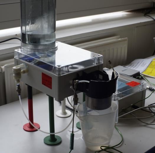
rapid than the GDP in the US [25]. Thus, the desire for an outdoor coffee machine,
which has high portability, is expected to be increased in the market. However,
there are not many portable coffee machines in the existing market. There are
some, but they are focused on small quantity extraction rather than mass
production. However, people often go out camping with a lot of companies.
Therefore, this project is going to focus on redesigning the portable coffee
machine which can extract a lot of amount of coffee within a short time.

The mobile coffee machine will mean easy to convey from one place to another. It
will also mean that the device must be easy to use in an outdoor situation. Thus,
additional components such as strap should be added, and the weight should be
cut down to allow user to easily carry.
Case Study - Opensource Espresso Machine (by Zack Moss)

 Figure 3.1, Prototype and final version of Zack Moss Espresso machine [26]

The opensource coffee machine project was also done in last year by Zack Moss
and published in blog [26]. In his project, De’Longhi espresso machine was reverse-
engineered, and then a new espresso machine was built through combining the
parts from various sources. The components were originated from the
disassembled De’Longhi machine, the online store or 3D printer. The electric
controller was replaced by the Arduino board. The control system was isolated
from the electrical parts to keep it safe. The pump holder, grouphead and machine
legs were printed by FDM type 3D printer. He also designed the experiment to
measure and analyse the water temperature, which comes out from the machine.
After evaluating the water temperature stability of the De’Longhi espresso
machine, he found a reasonable gain value for controlling the heater and pump,
Then, the gain value was applied into the device setting.

 7
University technicians, Chris Todd and Mike Herbert, who had supported the last
year project also advised this project. They advised not to focus on the electrical
control system. This advice was given due to the lack of compatibility on each
component with Arduino. Changing the control board means rebuilding the whole
machine, which is over-challenging to finish in one year. Also, supervisor, David
Polson, emphasised that this project should focus on mechanical engineering
rather than electrical or controlling engineering. Therefore, this project was aiming
to focus on manufacturing and redesigning the housing and outer frame rather
than the control board.

3.2 Need Statement
Based on the research, the need statement which clarifies the aim of the project
was constructed. Rather than changing and replacing the need statement, the list
was kept added when more considerable aspects came out.

This project will focus on building a portable coffee machine as an opensource
design. This final design of the device must be easy to carry. The device must be
safe. The progression of the project will be shared in the online blog. The comment
and feedback will be considered and applied to the project. The following
guidelines will further clarify the requirements:

 ✓ The machine must extract a coffee
 ✓ The extraction amount of coffee must be at least more than four
 portions, which are general number of a family member.
 ✓ The device must have light weight to carry by one hand.
 ✓ The device must protect the components from dust and dirt from
 outdoor.
 ✓ The electric components must be enclosed to prevent a hazard.
 ✓ The number of components must be few.
 ✓ Must be easy to get all the data related to this project, e.g. CAD file.
 ✓ Must be easy to purchase the components from an online store.
 ✓ It must be easy to build.
 ✓ The total cost of the device must not go over the budget (£300).
 + The machine must have a steaming function.
 + Coffee must be pre-ground before used in the device.
 + The coffee machine has flexible power sources.

 * + indicates post-added

 8
3.3 Identifying and Prioritising Requirements
The requirements have been categorised into four parts: performance, safety,
accessibility and cheap. Each requirement was listed on the table, and the
importance was weighted with the number one to ten. The higher number
indicates a more critical requirement for designing. The importance was weighted
to further applied in the Quality Function Development method.
Table 3.1, List of requirements

Requirements D/W Importance (1-10)

Performance

Extracting enough amount of coffee W 7

Lightweight W 6

Compact W 9

Comfortable to carry W 7

Safety

No sharp parts W 6

Electrical components enclosed from water D 10

Dust and dirty prevention W 8

Accessibility

Ease to build/ Simple design W 6

Access to components through shops W 8

Components available by CAD files W 8

Less use of components W 7

Inexpensive

Low production cost W 7

D: desire/essential, W: want/not essential

4 REVERSE ENGINEERING
Why an espresso machine?

The espresso machine was chosen for reverse engineering after comparing
different types of coffee brewing devices. There are various types of tools for
extracting coffee in the coffee market. For example, there are drip, French press,
percolator, bean-to-cup, and espresso. Each different method uses different

 9
operating principles. Filtering, French pressing, percolator methods were not
suitable for extracting a lot of amount in a short time. Bean-to-cup was convenient
and suitable for extracting a lot of amount but the size of the machine was bulky.
The commercial espresso, which is commonly used in café, has bigger and
expensive than bean-to-cut due to the high-end quality. However, there are also
compact style espresso machine for personal home usage. Therefore, the compact
size espresso machine was chosen finally.
Why De’Longhi EC685M

 Figure 4.1, Nespresso Essenza mini [27], De’Longhi EC685M [28]

After the compact espresso machine was selected for reverse engineering, the
De’Longhi EC685M was chosen and purchased. Before purchasing the machine,
two different devices were compared and discussed.

Nespresso Essenza mini was the first choice for reverse engineering. It is the first
company that introduced the capsule coffee into the market. Due to the
convenient and fast operation method, it becomes popular [27]. However, it
requires a separate milk forming device to make a milk-based coffee, and it only
accepts capsule coffee, thus it cannot use a ground coffee.

On the other hand, De’Longhi EC683M can extract coffee from the ground coffee.
It is also compact espresso machine. Unlike Nespresso machines, it has a
steamwand to make steamed milk for latte and cappuccino [28]. The £180 price
was reasonable based on the £300 budget limit. Furthermore, most of the parts
were possible to buy from the online store, and last year student used the same
machine. Hence, it was easier to get access to the product data. Therefore,
De’Longhi EC683M machine was reverse engineered.
Why were the components on the De’Longhi machine reused?

After the reverse engineering product was chosen, the remaining amount of budge
was only £120. Thus, rather than creating a whole new design or purchasing a new
main component from other resources, the project aim was targeting to change
and modify the existing machine into an opensource and portable design.

 10
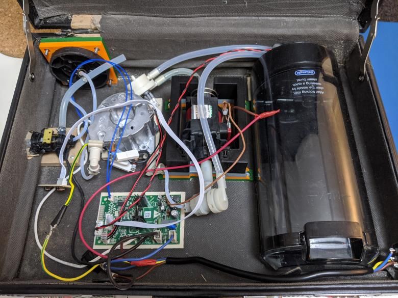
Therefore, through reusing the main components from the disassembled machine,
it was possible to progress the project without exceeding the budget limit.
Disassembling De’Longhi EC685M

Before disassembling the device, the related knowledge and data were all pre-
collected from the online resources. Assembly drawing supported for
disassembling the components without damaging the parts. Through using the Bill
of Materials, the component’s material and its purpose were analysed. Then, the
main specs of the espresso machine were linked with each element based on the
function. Finally, the main components’ features and operating principles were
further researched to understand the product more deeply.

Type of espresso machine: compact espresso machine

Manufacturer: De’Longhi

Model number: EC685M

 Figure 4.2, Assembly drawing of the EC685M [29]

1. The detachable parts such as water tank, grouphead and cup cover parts were
 all spaced out from the device.
2. The screws which can be approached from the outside were unscrewed. Two
 of them were located top backside of the main housing, the other one was
 placed on the grouphead, and the rest of them were put on the bottom part of
 the device.

 11
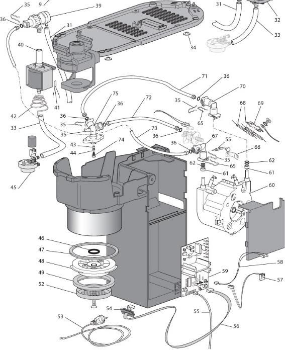
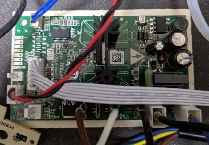
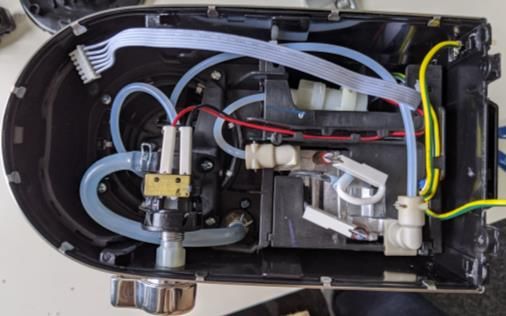
3. The top metal cover and the bottom part cover were detached from the
 housing. While removing the metal cover, the wire was unplugged from the
 switchboard.
4. The power switch and the related wire, which were located bottom part of the
 device, was removed
5. The water tubes, which related to steamwand and water tank, were
 disconnected.
6. The inner plastic housing was held up from the metal housing
7. All the wire was disconnected from the control board and pump and ground.
8. All water tubes were disconnected by removing the connecting pins
9. The screws holding the thermoblock and control board were unscrewed
10. Thermoblock, pump, steamwand valve and control board were detached.
11. The grouphead parts were detached.

 Figure 4.3, The Bottom View Disassembled Machine

 Figure 4.4, Top and Side View of the Disassembled Machine

 Figure 4.5, Control Board Wiring

 12
After the disassembling process was finished, the bill of materials was made to
analyse the materials used in the product. The material column on Table 4.1,Error!
Reference source not found. was added into the table through observing. Then, the
reason for each material’s usage was analysed. For instance, most of the frame
structures were made with ABS and stainless steel. ABS was chosen because of the
properties, which are cheap, light and strong. Stainless steel is rustproof, and it has
a high heat conductivity. Thus, it is ideal for the parts which are often contacting
with the water. Also, the stainless steel was used on the top cover, which is
designed for warming up the cups by released heat from the thermoblock.
Table 4.1, Bill of materials of De’Longhi EC685M

 Position. Part description Materials

 SLIDING BLOCK BLACK (PA66) ABS

 0 SCREW STAINLESS STILL

 0 HEATING ELEMENT SEAL

 0 INOX NUT M8 X 1 STAINLESS STILL

 0 INOX NUT M10 X 1.25 STAINLESS STILL

 1 COVER STILL

 2 MEASURING SPOON ABS

 3 Small one-cup filter STAINLESS STILL

 4 Large two-cup filter STAINLESS STILL

 5 Pod filter STAINLESS STILL

 6 SUMP STAINLESS STILL, ABS

 7 CUP PLATE STAINLESS STILL

 8 FLOAT ABS

 9 DIRT TRAY ABS

 10 FROTHER STAINLESS STILL, ABS

 11 COVER ABS

 13 KNOB ABS

 14 TUBE(SIL PLAT) DI=4 DE=8 SILICONE

 15 ASS. CONTROL BOARD

 16 MICROSWITCH

 17 TAP PLASTIC

 18 WATER TANK TRANSPARENT PLASTIC

 13
19 PROFILE LEFT ABS

20 JOINT PLASTIC

21 O-RING STAINLESS STILL

22 TUBE LOWER PLASTIC

23 TUBE DISTRIBUTING STAINLESS STILL, PLASTIC

26 PROFILE RIGHT STAINLESS STILL

27 SPRING STEEL

28 PUSH BUTTON ON/OFF ABS

29 SWITCH

30 GASKET RUBBER

31 TUBE DI=4 SILICONE

32 FILTERS ASSEMBLY PLASTIC

33 TUBE DI=4 DE=8 SILICONE

34 FOOT RUBBER

35 CLIP STEEL

36 O-RING D=3.85 SILICON

39 VALVE ABS

40 PUMP

41 PROTECTOR ABS

42 SPRING STEEL

43 VALVE ABS

44 RING STAINLESS STEEL

45 FLOWMETER

46 GASKET ABS

47 GASKET ABS

48 SUPPORT ABS

49 GASKET ABS

52 DOFFISER STAINLESS STEEL

53 POWER SUPPLY CORD

54 RUBBER PAD RUBBER

55 SENSOR NTC

56 WIRING

 14
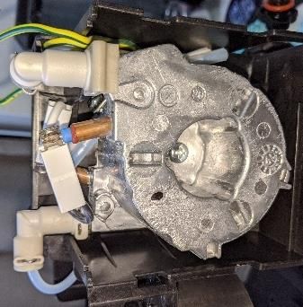
57 CONNECTOR ABS

 58 WIRING

 59 POWER BOARD

 60 GENERATOR STEEL, CUPPER

 61 SPACER 5XD5.2XD7.9 NATURAL STAINLESS STEEL

 62 GASKET ABS

 65 CLIP STEEL

 66 BRACKET ABS

 67 CONNECTION ABS

 68 TCO 192”

 69 TCP BRACKET

 70 CONNECTION ABS

 71 TUBE PTFE DI=2 DE=4 SILICON

 72 TUBE PTFE DI=2 DE=4 SILICON

 73 TUBE PTFE DI=2 DE=4 SILICON

 74 SPRING STEEL

 75 CONNECTOR ABS

All the parts are available to buy from the De’Longhi official website.
Total number of parts: 75
Further research on the main components

The main components, such as thermoblock, thermocouple, pump, water tank,
volume flow meter and relay, were further researched. In addition, the principle of
the operation and other parts’ types used in other espresso machines were
investigated.
Heater

 Figure 4.6, thermoblock from the EC685M

 15
De’Longhi EC685M uses a thermoblock to heat the water. However, in the market,
other machines use a single boiler or dual boiler. The advantages and
disadvantages of them are compared in Table 4.2.

As Table 4.2 shows, the thermoblock used in the De’Longhi EC685M was decided
to be reused in the new design. Considering not only the budge but also other
aspects such as performance, reusing thermoblock was reasonable. Based on the
heating performance, the dual boiler was the best choice. The project was
targeting to make a portable espresso machine. Hence, the considering the size of
the heater was important. The single boiler was another choice, but the water in
the boiler needs to be refilled manually. Thus, the single boiler was not suitable for
extracting a lot of amount of coffee in a short time. Therefore, the thermoblock
obtained from the espresso machine was planned to be reused in the new design
[30].
Table 4.2, Single boiler, Thermoblock, Dual boiler comparison [30]

 Single boiler Thermoblock Dual boiler

Temperature stability Low Middle High

Brewing and steaming Unable Able Able
simultaneously

Boiler refill Manual Automatic Automatic

Size Small Middle large

Cost Low Middle High

 Not good for making Recommend for Good for large quantity
 a lot of coffee. milk-based coffees
 Recommend for milk-
 based coffees

Thermocouple and Amplifier

In the machine, a thermocouple was connected on the output port of the
thermoblock. A thermocouple is an electrical device which creates a voltage
depending on the temperature. The voltage produced due to the thermoelectric
effect. As shown in Figure 4.7. This effect occurs when two different material wires
are joined, and one side is heated. Due to the correlation between temperature
and voltage, the temperature can be calculated by the measured voltage. There is
various type of thermocouple due to the differences in their used materials. Each
of those types has different properties such as usable temperature range and

 16
tolerance of the measured temperature. They are identified by type name like K, J,
N, R, etc [31].

The thermocouple cannot be used independently due to the low amount of
produced voltage, which has micro-scale. Thus, it is essential to use an amplifier to
increase the scale of the voltage to a readable scale. In this espresso machine, the
amplifier was integrated onto the control board, so it was difficult to disassemble
and investigate it further [31].

 Figure 4.7, Thermoelectric effect [31]

Pump

 Figure 4.8, Pump inside EC685M

For espresso machine, there are two main pump types: vibratory and rotary. They
both have advantages and disadvantages of using an espresso machine. Those
features are tabulated in Table 4.3. For the EC685M, this machine was aiming to be
a compact home espresso machine. Thus, the vibratory pump was chosen, which is
relatively more compact than the rotary pump. The new design used the existing
pump due to the portability, which was one of the requirements for the design.
Table 4.3, Rotary Pump Vs Vibratory Pump [32]

 Rotary pump Vibratory pump

Advantages Long lifetime Inexpensive

 Less noise Compact size

Disadvantages Large size Have more noise than a rotary pump

 5 to 6 years of lifetime

 17
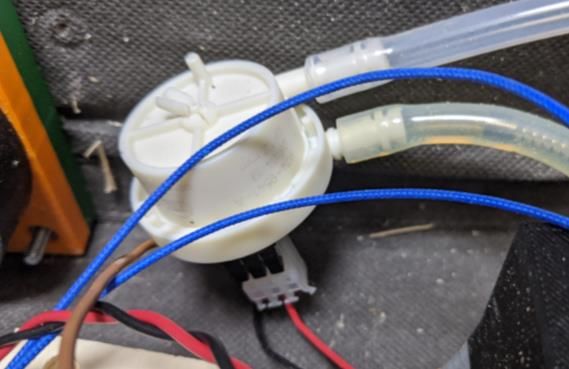
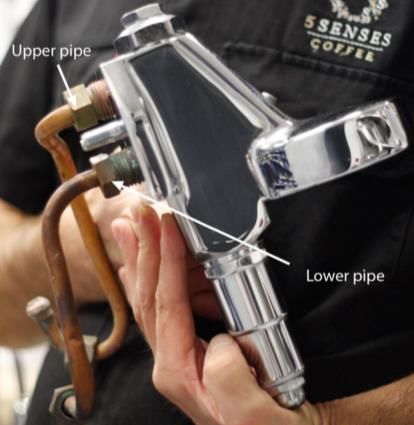
Grouphead

 Figure 4.9, E61 Grouphead [33], De’Longhi EC685M Grouphead

Grouphead is a part that located in the front of the espresso machine. This part
connects with the portafilter. Grouphead is one of the most important part in
espresso machine because inside the grouphead the water and coffee powder
meet. The main function of the grouphead is sustaining the water temperature
comes from the heater, thus, is usually made with metal [33, 34]. However,
professional grouphead such as E61 grouphead cost minimum around £400.
Therefore, this project is going to focus on using the existing grouphead which is
made with plastic, rather than buying a new grouphead,
Water tank

 Figure 4.10, Watertank Parts

The water tank parts were composed with a reservoir and the connector. The
connector has two connecting holes that one is linked with the volume flow meter
and pumps input, and the other one is connected with the output of the pump
which is also spreading out into the grouphead.

 18
Volume flow meter

 Figure 4.11, Volume Flow Meter

A flow sensor is a device which measures the volume flow rate of the liquid or gas.
A flow rotates the turbine inside the sensor and generates a small amount of
electricity. The flow rate is proportional to the voltage, so it is possible to calculate
the flowrate by voltage. Through using Equation 4.1, the volume of the flow past the
sensor can also be calculated. Q indicates volume flow rate. C is flow velocity and A
is the surface area of the pipe. For this espresso machine, the flow sensor will be
used to adjust the amount of water used for extracting the coffee by adjusting the
pump operating time.
 = CA
 Equation 4.1

Relay
High voltages such as 110v or 220v are used in pump and heater of the espresso
machine. However, the control board cannot address this high voltage directly.
Thus, it is possible to expect that the relay is integrated on to the control board.
Relay is a switch which electrically operates. It can allow controlling the high
voltage supply with the digital signal created from the control board. Figure 4.12
well describes the principle of the relay. The left side of Figure 4.12 shows an open
condition of the circuit 2 which has high voltage, and the right side shows close
condition. At the open condition, the circuit number 1 does not provide electricity
to the electromagnet. Thus, the circuit 2 will not be closed. When the circuit 1
supplies the voltage to the electromagnet, the switch on the circuit 2 moves and
close the circuit 2. Therefore, on the espresso machine, the control board will turn
on and off the electricity supply to manage the pressure and temperature.

 19
Figure 4.12, Relay Operation Principle [35]

Specs and Components relationship

The specs listen on Table 4.4 was matched with the components in espresso
machine while disassembling. For example, the 1.1L of water tank capacity is set by
the water tank size, which has a part number 18. Also, the machine has three
different colour selections because of the three different available colours on the
outer frame parts. Through doing this process, the relationship between function
and the components could be clearly identified.
Table 4.4, Performance Specification of De’Longhi EC685M [28]

 Feature Value

 Weight 4,2kg

 Rated voltage/Frequency 220-240 V / 50-60Hz

 Input power 1300W

 Pump pressure 15bar

 External dimensions 149x330x303 (WxDxH) ( 3 )

 Water Tank Capacity 1,1L

 Number of filters 3

 Maximum cup height 12cm

 Body material Stainless Steel, ABS

 Milk system Manual

 Heating system Thermoblock

 Cup warmer Passive

 Available colour Black, Red, Metal

 On/off switch: ✓

 Auto shut-off: ✓

 20
1&2 cups filters: ✓

 Removable drip tray: ✓

 Removable water tank: ✓

 Water level indicator: ✓

 ESE (Easy Serving Espresso) pods: ✓

5 DESIGN SPECIFICATION
In this section, the design requirement was quantified into specification. Then the
specification was evaluated and ranked according to QFD. The design requirement
and need statement were guidelines for the project. Since they could not be
directly measured and calculated, those guidelines were difficult to directly apply
into the decision process. Thus, the specification is needed to quantify the
requirement to be used in decision making. The design requirement was
restructured with using more engineering terms in order to measure and
calculate. When the specification is all listed, the importance of each aspect was
analysed by the performance specification method and QFD method. Firstly, the
performance specification method was used for listing all the specifications. Then,
based on correlation between requirement and specification, the ranking of the
specification was evaluated. Furthermore, the ranked and weighted values of the
specification were utilised during the selection of the design concepts.
Performance Specification Method

Six different specifications, which can be adjusted through progression the
project, were chosen. Then, it was listed on the table with the minimum targeting
values.
Table 5.1, Performance Specification Method

Metric Value

Number of parts < 75 (Less than original machine)

Size < 500 x 350 x 120 3

Weight < 4.2kg without water

Ratio of accessible parts -

Production cost < £300

Electric parts enclosed 100%

 21
Quality Function Development method (QFD)

Through using the QFD method, the ranking and weighting value of each
specification was calculated. This was done to identify which specification is more
important and further used when making decision. To calculate and evaluate, the
specification was listed on the top of the raw on QFD table, and the requirements
were listed on the left side of the column. Then, the strength of the relationship
was evaluated with number 1,3 and 9. The technical importance score was
calculated by adding all the multiplied values between customer importance rating
and the relationships value. By the resulting technical importance scores, the
ranking of the specification can be determined, and this ranking can be used on
making the right decision while designing the prototype and final design. In
addition, the correlation is indicated by positive, negative and none on the top of
the chart. This shows how the specification are relating to other specification.
Thus, if it is positive then the relationship is proportion. If it is negative, then it is
having a reverse proportion relationship [36].

Table 5.2 shows the ranking of the specification, but the score represent that the
number of parts and size have almost the same technical importance. The QFD
chart allows the designer to not only recognise the ranking of the specification but
also help to evaluate the design concept by calculation through using the numbers.
The QFD chart was further used on the next chapter when evaluating and selecting
the design concepts.

 22
Table 5.2, Quality Function Development Method

6 DESIGN CONCEPTS
On this part, the design ideas and concepts were brainstormed and selected. The
design ideas of each component were brainstormed based on their function. At
least more than three ideas were listed on each category. Then, the plans were
evaluated by using the QFD method and selected based on the resulting score the
concept gets.
Concept development
The conceptual design of each function has been brainstormed. Then, the ideas
have been organised in Table 6.1 with the brief drawing and explanation of the
principle.

 23
Table 6.1, List of Conceptual Design

 Options 1 Options 2 Options 3

 Method of
 transportation

 Handle Wheel Strap

 Dirt prevention
 device for
 grouphead

 Rotating slide cover Fitting cover with string Sliding cover
 connection

 Steam wand

 Fitting steamwand The tube extended Steamwand and
 steam wand with grip container inside the
 housing

Concept evaluation by QFD
Each organised part concept was combined into a sketch to demonstrate the initial
options of the prototype design. These concept prototypes were evaluated by the
QFD method. For the transporting method, the strap was chosen. For the
grouphead cover, the fitting cover with string connection was selected. Finally,
steamwand was planned to extend its tube and add grip on to it.

 24
Table 6.2, Concepts evaluation by QFD

 Directly connected

 Steamwand inside
 Lined Steamwand
 Rotating cover

 Sliding cover

 Fitting cover

 steamwand
 Handle

 Wheel

 Strap
 Weighted
 ↓Requirements Score

 Performance 0
 Extracting enough amount of
 0
 1 coffee
 2 Lightweight 126 4 3 4 4 3 3
 3 Compact 135 4 2 4 4 3 4
 4 Comfortable to carry 133 2 4 3 3 3 3 2 3 4
 Safety 0
 5 No sharp parts 0
 6 Electrical components enclose 90 4 4 2
 7 Dust and dirty prevention 24 3 3 3 2 2 3
 Accessibility 0
 8 Easy to build/ Simple Design 147 4 2 4 4 2 4 3 4 2
 9 Possible to buy parts in store. 81 3 2 3 3 2 4
 10 Parts available by CAD files 16 4 2 4
 11 Less number of components 142 4 2 4 3 2 4
 Inexpensive 0
 12 Low production cost 44 4 1 4 3 2 3
 938 2381 1586 2514 2968 2114 3191 1619 1773 1456

Based on the calculated values by QFD, strap, fitting cover and extended
steamwand with grip have been chosen for the basic concepts for the prototype.

7 MANUFACTURING DESIGN
After the design concepts were chosen, the prototype was begun to build. The
rapid prototype was focused on building a working model. Then, based on the
experience gained from the prototype, the final prototype was planned to build. All
the decisions were justified by comparing available options, especially using the
QFD method.

7.1 Prototyping

 Figure 7.1, Briefcase [37]

 25
The main body frame was chosen to use a briefcase because it was relatively
inexpensive and had handle on it. According to the result of the concept evaluation,
the strap was chosen. Nevertheless, the handle was included on the case, thus the
hand was used rather than installing the strap.

University technicians advised to use the original pump housing structure. This
advice was given because of the difficulty of controlling the pump vibration.
Therefore, for the prototype, the pump housing was made through reverse-
engineering the original structure of the pump housing to minimises the pump
vibration.

Rather than redesigning the grouphead from the prototype, the existing grouphead
was mounted onto the briefcase by using the additive manufactured holder. As
Figure 7.2 shows, the CAD models were designed by Fusion360 to 3D printed.

 Figure 7.2, Grouphead Holder, Grouphead Cover, Pump Holder.

Additive Manufacturing the parts

Additive manufacturing is an automotive manufacturing device which creates the
product layer-by-layer with Computer-aided design (CAD) file. It can use various
kind of materials, such as plastics, metals, etc. The University of Sheffield provides
two types of AM devices from student workplace. The two kinds of AM were FDM
(Fused Deposition Modelling) and SLA (Stereolithography). FDM and SLA have
different operating methods, so they have various advantages and disadvantages.
The differences are listed in Table 7.1. In this project, FDM was chosen for
manufacturing parts due to the low cost, which can increase the accessibly as an
opensource project, and the relatively low design requirement for dimension
accuracy.

 26
Table 7.1, FDM vs SLA [38]

Type FDM SLA

Device

 Ultimaker 2+ Extended Prusa MK3S

Precision Relatively low Relatively high

Postprocessing Need to remove supports Need to remove stick resin by
 alcohol

Cost Low cost Relatively high cost

 1kg of filament is around $25 2.5L of resin is about $60

 Platform $100

Recommended Rapid prototyping When precision is important
situations for using Low-cost models manufacturing
 When it does not require high
 Hobbyists durability

 When precision is not important For creating moulds

FDM not only shows the high-cost efficiency but also it is the most popular AM
process, which occupies 69% of AM technology usage [39]. For this coffee machine
project, one of the essential requirements will be the accessibility of the resources,
so this project will focus on using FDM rather than SLA.

Due to the layer-by-layer operating principle and the limitation of the nozzle shape,
to make reliable FDM results, there were several vital points to consider while
designing the CAD file and printing it [40].

1. 1.2 to 1.5mm thickness support structures are required when the angle of the
 edge is lower than 45 degree.
2. Minimum wall thickness is 1.5 to 2mm due to the size of the nozzle.
3. Thicker the better with the strength, but it increases the required time and
 cost. Thus, it is crucial to find a design that provides both enough strength and
 efficiency.
 27
4. Result of the FDM comes out with slightly smaller than the original CAD file.
 Therefore, when designing a hole, the dimension of diameter should be
 increased by 3% up to 10mm.
5. Perpendicular thread needs to be avoided, and the recommended thread angle
 is 29 degree with 0.8mm minimum thickness.
6. The upward-facing surface has the best surface finish, and curved design shows
 less surface finish.
7. It is better to change the hole’s orientation into a vertical direction to avoid
 support usage.
8. Infill rate is one of the essential factors when using FDM. It shows the density of
 the inside parts, so higher the stronger but higher requires more time and cost.
Result of the Additive Manufactured parts

 Figure 7.3, Printed Parts: Grouphead Holder, Grouphead Cover, Pump Holder.

Used Additive manufacture machine: Ultimaker 2+ Extended
Material: PLA

After comparing the FDM and SLA, the FDM was chosen to be used for printing out
the parts. There was some concern about the quality of the printed parts. As an
article [41] reported that FDM is not reliable enough.
Assembling parts

Before assembling the parts, the silicon tube was purchased from the online store
for replacing the short silicon tubes. The university workplace provided the bolts
and nuts, so they were not required to be bought.

Four different holes were made on the briefcase. A hole for the grouphead was
built on the bottom right side of the briefcase by a 40mm radius hole saw. 8mm
diameter holes were made on the right side of the briefcase and the top-right side
of the plane. The right-side hole was for the knob, and the top right-side hole was
for the steamwand tube. The fourth hole was made for the IEC connector. This

 28
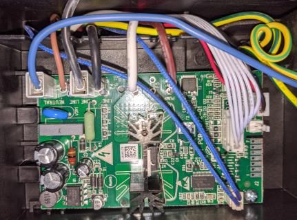
hole was made by drilling the hole and then cutting into the desired shape by using
the fret saw.

The three different sizes (100x80, 80x80, 40x40 2 ) of plywood were made and
fasten on to the briefcase. Each plywood was jointed onto the briefcase with two
screws. The control board was glued on to the 100x80 plywood by glue gun. The
thermoblock was fastened onto the 80x80 plywood with one screw. The knob
parts for switching the steaming function was fastened on to the 40x40 plywood by
two screws.

The grouphead which was extracted from the original coffee machine was fitted
with the grouphead holder. Then, the grouphead was fixed on to the grouphead
hole on the briefcase by four sets of bolt and nut.

 Figure 7.4, Steamwand Controller, Control Board, IEC C13

The thermoblock was fastened on to the plywood by screw. The pump holder was
tightened on to the briefcase by using four-screw. Then, the pump was mounted
on to the holder. A part holding a water tank was extracted from the original body
by sawing and fasten onto the briefcase by using the glue gun and screws. IEC
female connector was fixed onto the briefcase with two screws.

 Figure 7.5, Inside the Prototype

 29
All the electric wires and water tubes were connected by following the original way
from the De’Longhi espresso machine. For the IEC connector, the power cables
including plus, minus and ground were soldered on to the IEC female connector
with the correct match.

7.1.1 Testing and Discussion

The result of the prototype was compared with the original espresso machine.
Based on the targeting specifications, the weight and the number of parts had been
successfully decreased. The weigh had been reduced from 4.2kg to 4.0kg, and the
Number of total parts has reduced from 75 to 58. The size of the machine has
reduced, and the shape of the device becomes simple. Therefore, the espresso
machine became more convenient to carry and manufactured.

Before manufacturing the prototype, there was some concern with using additive
manufacturing. The tolerance of the grouphead cover for adequately fitting on to
the grouphead hole was concerned due to the limitation of dimensional accuracy.
FDM has weak strength comparing to other AM process. Thus, there was also a
concern that the strength of the result is not enough to bear the vibration or
applied force on the parts. However, the actual result was strong enough to bear
the force applied by the screw.

The holder on the briefcase was convenient and strong enough to bear the weight
of the device. Thus, replacing the strap to holder was reasonable decision. There
was an issue with the electrical parts enclose because the original water tank was
not sealed. This issue was planned to be improved in the final design.

The espresso machine worked well. It showed the same performance compared to
the original product. However, there were still more parts that need to be replaced
by the opensource hardware. In addition, the university students from the
workplace gave a feedback that the machine looks like a bomb. Therefore,
referring to those result and feedback, the final design was structured.

7.2 Final Design
Based on the experience, which was obtained from the prototyping, the final
design was planned. Unfortunately, the final design could not be manufactured
because of the university facilities shutdown due to the COVID-19. Nevertheless,
the final design was planned. In this section, the IEC connector was reselected, the
briefcase was replaced by a laser-cut acrylic case, the water tank was redesigned.

 30
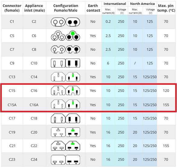
IEC connector
From the prototyping, the IEC C13/C14 was installed for safety issues. However, the
IEC connector was chosen without any research about the difference between
each type. It was just installed due to the recommendation by the technicians. The
further research about IEC connector was done lately. Through this research, the
problem that IEC C13/C14 was not suitable for the espresso machine was
recognised.

IEC stands for International Electrotechnical Commission. Based on their
agreement, a lot of electrical components have been standardised. One of the
standard rules is IEC 60320, and it specifically represents the power supply
connector for household or its related devices. IEC 60320 has several different
types, and they are composing a couple by female and male type connectors. Each
connector has different durability for current, voltage and pin temperature. Those
differences are listed in Table 7.2. Apart from C15/C16 and C15A/C16A, all the other
connector shows 70 degrees of maximum pin temperature. However, for the
espresso machine, the heated water reaches up to more than 90 degree Celsius.
This indicates that the C13/C14 connector cannot bear the water temperature of
the espresso machine. Therefore, the C15/C16 or C15A/C16A type must be used for
this project. Besides, the C15/C16 connector is commonly used for an electric
kettle. Thus, it will also be suitable for the espresso machine [42].
Table 7.2, IEC 60320 [42]

 31
Redesigning a Housing

There was a feedback from other students while working inside the workplace.
Two students said that the product looks like a bomb because of the black colour
briefcase. There were some changes made in appearance of the final design.
Moreover, the briefcase was only supplied by the Irish online shop, which is not
internationally reachable. Thus, the briefcase was redesigned to be
manufacturable at home instead of purchasing.
Table 7.3, Final Design Concept Development

 1st prototype Option 1 Option 2

Housing Briefcase Laser-cut acrylic 3D printed housing

Water tank design Original parts from the Plastic bottle using a bladder water tank
 espresso machine check valve

For replacing the briefcase design, the new design was planned to use laser-cutting
or 3D printing method. The laser-cutting was chosen for manufacturing the new
housing. This decision was made by comparing the benefits of each method by the
QFD method, as shown in Table 7.4.

As Figure 7.6 shows, the housing was designed by Fusion360. The connecting parts
were designed with zigzag pattern to increase the contacting areas between
components to improve the strength of the bond. The estimated mass of the
machine case was 2,035 g which is 410g lower than the briefcase. The screw holes
were not drawn on the initial CAD file because of the concern of the unperfect
location matching between holes and components. The screw holes were planned
to be added on the CAD files after manufacturing and measuring the exact location
of the holes. 900 x 600 x 5 3 acrylic sheet needs to be cut by a laser-cutting
machine. Each part was planned to be adhesive by plastic weld glue to prevent
whitening of the plastic sheet by other types of glue.

 Figure 7.6, Computer Aid Design of the Acrylic Housing

 32
Redesigning a Water Tank

For the water tank, the prototype used the original parts from the De’Longhi
machine. Unlike other components, the housing cannot be purchased individually
from the online parts store. Therefore, the water tank was redesigned with using
parts that are easy to purchase or obtain from other resources.

There were two ideas. One was using a disposable plastic bottle with a check valve
to sustain the pressure inside the bottle. This was important to sustain the pump
function. The other idea was using a bladder water bag, which is shown in Figure
7.7, This idea can sustain the pressure inside by shrinking the structure. These two
main designs were evaluated in Table 7.4 with QFD method. As a result, the Bladder
water tank design was chosen.

 Figure 7.7, Bottle & Check valve [43, 44], Bladder Water Bag [45]

Table 7.4, Final Design Concept Evaluation by QFD

 Bottle & check valve

 Bladder water tank
 Laser Cut acrylic

 Original parts
 3D printed
 Briefcase

 Weighted
 ↓Requirements Score

 Performance 0

 1 Extracting enough amount of coffee 0
 2 Lightweight 126 1 3 4
 3 Compact 135 3 3 3 1 3 4
 4 Comfortable to carry 133 3 3 3 1 3 3
 Safety 0
 5 No sharp parts 0 4 4 5

 6 Electrical components enclose 90 1 4 4
 7 Dust and dirty prevention 24
 Accessibility 0
 8 Easy to build/ Simple Design 147 2 3 3 1 2 4

 9 Possible to buy parts in store. 81 2 4 4 1 3 3

 10 Parts available by CAD files 16 5 5

 11 Less number of components 142 3 4 3 2 3 4
 Inexpensive 0
 12 Low production cost 44 2 4 3

 938 1774 2393 2207 996 2505 3202

 33
7.3 Final Design Evaluation
The final design was evaluated based on the specifications and requirements which
were set at the initial step of the project process.

As shown in Table 7.5, the performance of the final design outstands the prototype
apart from the cost perspective. The cost has increase about £20. However, the
size, weight, accessibility of parts and electrical parts enclose have improved a lot.
The size and weight have been reduced because of redesigning the housing with
Acrylic. This has enhanced the portability of the espresso machine. Even though
the total part number had not decreased dramatically, the accessibility of the parts
has improved due to changing the water storage components. Therefore, the final
design can be evaluated as a good design according to these improvements.
Table 7.5, Evaluating Products based on Specification

 Original Machine Prototype Final Design

 Number of parts 75 58 57

 Size 500 x 350 x 120 3 440 x 323 x 102 3 385 x 320 x 88 3

 Weight 4.2kg 4.0kg 3.6kg

 Ratio of accessibility parts - 90% 100%

 Production Cost £180 £205.68 £226.78

 Electrical parts enclosed 100% 70% 100%

Table 7.6, Bill of Materials

 Prototype Final Design

 No. Part description Materials No. Part description Materials

 Original Parts

 1 Large two-cup STAINLESS STILL 1 Large two-cup STAINLESS STILL
 filter filter

 2 SUMP STAINLESS STILL, ABS 2 SUMP STAINLESS STILL,
 ABS

 3 FROTHER STAINLESS STILL, ABS 3 FROTHER STAINLESS STILL,
 ABS

 4 KNOB ABS 4 KNOB ABS

 5 MICROSWITCH 5 MICROSWITCH

 6 TAP PLASTIC 6 TAP PLASTIC

 7 WATER TANK TRANSPARENT -

 34
You can also read