Owners Parts Service Tuning - Cobra Moto
←
→
Page content transcription
If your browser does not render page correctly, please read the page content below
Owners Parts Service Tuning
For parts orders contact your local dealer

   To locate your closest Cobra dealer
                log on to
       www.cobramotorcycle.com
                  or call
             (517) 437 9100

    If you need technical assistance
      contact your local dealer or call
 the Cobra Technical Support Hotline at
            +1(517) 437 9100

               Cobra MOTO, LLC
                 240 Uran Road
               Hillsdale, MI 49242

                       2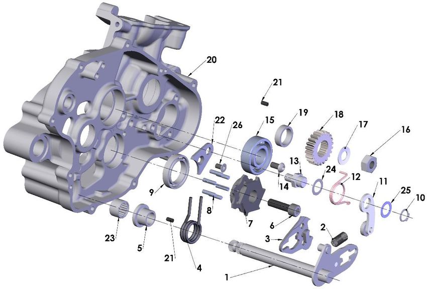
DISCLAIMER OF WARRANTY

This motorcycle is sold “as is” with all faults, obvious or not. There are no warranties
expressed or implied, including any warranty of merchantability and warranty of fitness for
any particular purpose.

                                  “WARNING”
THE COBRA CX65 IS A COMPETITION MODEL ONLY AND IS NOT MANUFACTURED
FOR, NOR SHOULD IT BE USED ON PUBLIC STREETS, ROADS OR HIGHWAYS.

THE USE OF THIS BIKE SHOULD BE LIMITED TO PARTICIPATION IN SANCTIONED
COMPETITION EVENTS UPON A CLOSED COURSE BY A SUFFICIENTLY SKILLED
RIDER AND SHOULD NOT BE USED FOR GENERAL OFF-ROAD RECREATIONAL
RIDING.

IMPROPER USE OF THIS MOTORCYCLE CAN CAUSE INJURY OR DEATH.

THIS BIKE IS INTENDED FOR EXPERIENCED RACERS ONLY AND NOT FOR
BEGINNERS.

IT IS YOUR RESPONSIBILITY AS THE OWNER OF THIS COBRA MOTORCYCLE OR
AS THE PARENT, OR LEGAL GUARDIAN OF THE OPERATOR, TO KEEP THIS
COBRA MOTORCYCLE IN PROPER OPERATING CONDITION.

THIS BIKE WAS DESIGNED FOR RIDERS THAT WEIGH LESS THAN 110 LBS WITH
FULL RIDING GEAR AND SHOULD NOT BE OPERATED BY RIDERS THAT WEIGH
MORE THAN THAT.

BE SURE THAT THE RIDER ALWAYS WEARS ADEQUATE SAFETY GEAR
EVERYTIME HE OR SHE RIDES THEIR COBRA MOTORCYCLE.

                        IMPORTANT SAFETY NOTICE

Failure to follow WARNING instructions could result in severe injury or death to
the machine operator, a bystander, or a person inspecting or repairing the
machine.

CAUTION:
A CAUTION indicates special precautions that must be taken to avoid damage to
the machine.

NOTE:
A NOTE provides key information to make procedures easier or clearer.
                                                                              MCC62021.2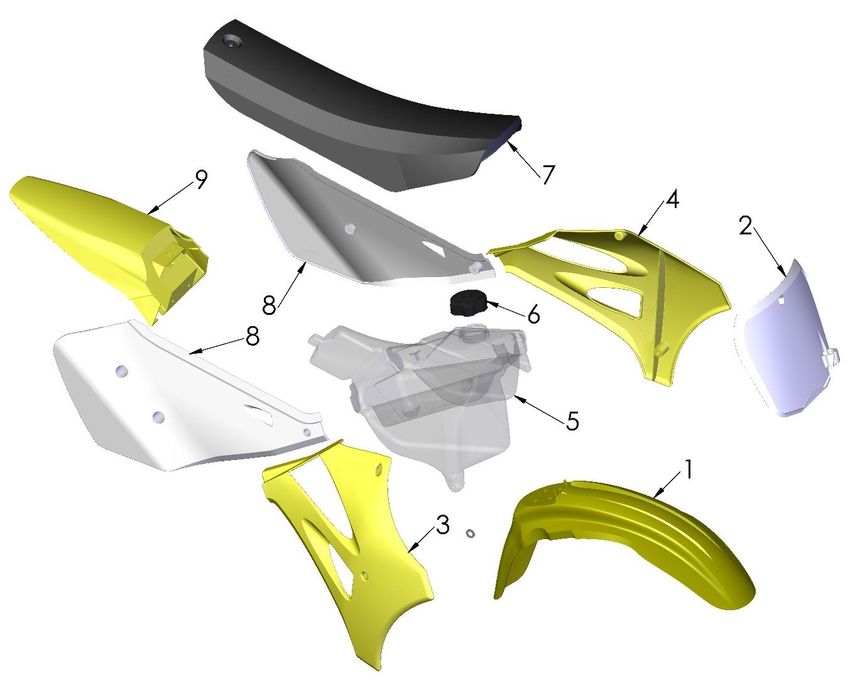
Table of Contents
GENERAL INFORMATION............................................................................................. 6
   SPECIFICATIONS - GENERAL .......................................................................................... 6
   OPTIONAL COMPONENTS ............................................................................................... 7
   SPECIFICATIONS - TORQUE VALUES ............................................................................... 8
   BREAK-IN PROCEDURE .................................................................................................. 9
   STARTING PROCEDURE ............................................................................................... 10

MAINTENANCE............................................................................................................ 11
   TIPS ........................................................................................................................... 11
   SCHEDULE .................................................................................................................. 11
   REPLACING TRANSMISSION / CLUTCH LUBRICANT ......................................................... 12
   CHAIN ADJUSTMENT .................................................................................................... 13
   LEVER ADJUSTMENT ................................................................................................... 14
   REAR BRAKE MAINTENANCE ........................................................................................ 14
   AIR FILTER CLEANING ................................................................................................. 16
   FORK MAINTENANCE ................................................................................................... 16
   FORK AIR BLEEDING ................................................................................................... 17
   FORK OIL REPLACEMENT ............................................................................................ 17
   IGNITION TIMING ......................................................................................................... 19
   CABLE TIES ................................................................................................................ 20

PARTS .......................................................................................................................... 21
   PARTS – AIR BOX & INLET SYSTEM .............................................................................. 21
   PARTS – BARS AND CONTROLS .................................................................................... 22
   PARTS - CARBURETOR ................................................................................................ 23
   PARTS – CLUTCH – MASTER CYLINDER ........................................................................ 24
   PARTS – COOLANT SYSTEM ......................................................................................... 25
   PARTS – ELECTRICAL SYSTEM ..................................................................................... 26
   PARTS – ENGINE CLUTCH ............................................................................................ 27
   PARTS – ENGINE – CLUTCH / KICK COVER .................................................................... 28
   PARTS – ENGINE – IGNITION SIDE ................................................................................ 29
   PARTS – ENGINE – KICK MECHANISM & WATER PUMP .................................................. 30
   PARTS – ENGINE – SHIFT MECHANISM ......................................................................... 31
   PARTS – ENGINE – TOP END ....................................................................................... 32
   PARTS – ENGINE – TRANSMISSION ............................................................................... 34
   PARTS – ENGINE – POWER VALVE ............................................................................... 36
   PARTS – EXHAUST SYSTEM ......................................................................................... 37
   PARTS – FORKS & TRIPLE CLAMPS .............................................................................. 38

                                                                 4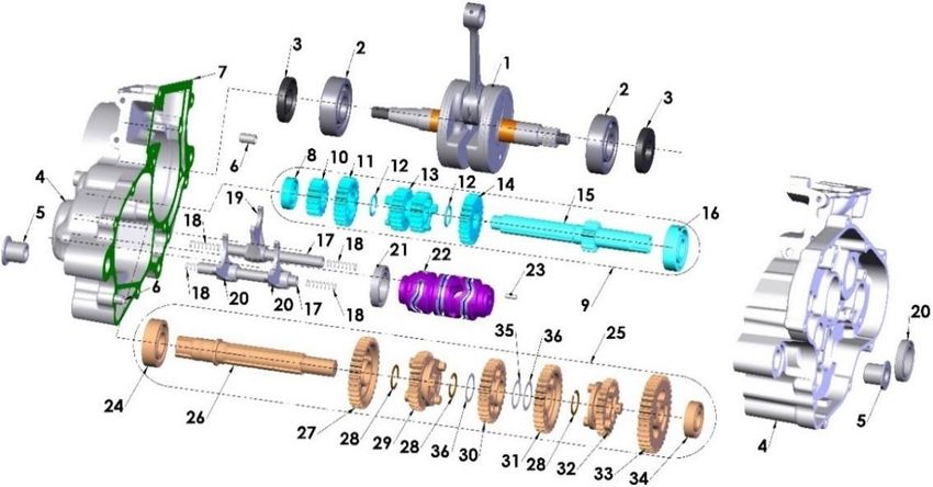
PARTS – FORK – LEG ASSEMBLY – BRAKE SIDE............................................................ 40
   PARTS – FORK – LEG ASSEMBLY – NON-BRAKE SIDE ................................................... 41
   PARTS – FRAME .......................................................................................................... 42
   PARTS – FRONT WHEEL .............................................................................................. 43
   PARTS – FRONT BRAKES – MASTER CYLINDER ............................................................. 44
   PARTS – FRONT BRAKES – CALIPER............................................................................. 45
   PARTS – PLASTIC BODYWORK & SEAT ......................................................................... 46
   PARTS – REAR BRAKE ................................................................................................. 48
   PARTS – REAR WHEEL ................................................................................................ 49
   PARTS – SHOCK EXTERNAL ......................................................................................... 50
   PARTS – SHOCK – INTERNAL ....................................................................................... 51
   PARTS – SWINGARM ASSEMBLY ................................................................................... 52

SERVICE ...................................................................................................................... 53
   ENGINE SERVICE ........................................................................................................ 53
     Base Gasket Selection .......................................................................................... 54
   POWER VALVE ............................................................................................................ 55
   EXHAUST .................................................................................................................... 57
   FUEL & AIR SYSTEM .................................................................................................... 57
   CARBURETOR: ............................................................................................................ 57
   REAR SHOCK .............................................................................................................. 58
   BRAKES...................................................................................................................... 59
     Rear Brakes .......................................................................................................... 59
     Front Brakes .......................................................................................................... 60
   FRONT WHEEL ............................................................................................................ 60
     Assembly ............................................................................................................... 60
   IGNITION ..................................................................................................................... 61

TUNING ........................................................................................................................ 62
   GEARING .................................................................................................................... 62
   SUSPENSION .............................................................................................................. 63
     Adjustment: ........................................................................................................... 63
     Front Fork Operation ............................................................................................. 63
     Fork Damping Adjustments ................................................................................... 64
     Rear Shock Adjustments ....................................................................................... 65
   CARBURETOR ............................................................................................................. 66

TROUBLESHOOTING .................................................................................................. 68

                                                                5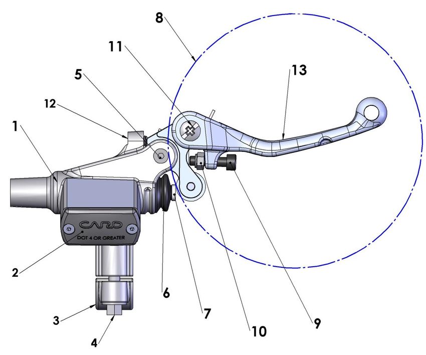
General Information
Specifications - General
             Items                                         CX65
Dimensions
 Wheelbase                         40.9” (1040mm)
 Wheel size                        12” (305mm) rear, 14” (356mm) front
 Seat height                       29.9” (760mm)
Engine
 Type                              2-stroke, single cylinder, reed valve
 Cooling system                    Liquid-cooled
 Coolant                           Spectro Year - Round Super Coolant
 Displacement                      64.9 cc
 Bore and stroke                   44.5 mm x 41.7 mm
 Ignition system                   Electronic, digital advance
 Spark plug                        Autolite 4063 or XS4063
    Gap                            0.024” – 0.026” (0.60 – 0.65 mm)
 Ignition timing                   Digital advance (set at “0” timing mark)
 Fuel type                         High octane pump gasoline
 Premix Oil type                   Spectro Platinum SX2
 Premix oil ratio after break-in   32:1
 Carburetion                       26 mm VM Mikuni
    Main Jet / Slow (Pilot) Jet    280 / 42.5
    Needle                         5l 14 - 4
        Needle clip position       4th slot from top of needle- stock position
    Float Height                   21.1 ± 1.0
Transmission                       6 speed
 Final drive ratio                 14/45
 Chain                             112 links 420
 Transmission / clutch oil type Spectro Golden SAE 80 Gear Lube
   Quantity                        530 ml (18.0oz)
Chassis
 Front tire                        60/100 – 14
 Rear tire                         80/100 – 12
 Front fork                        CARD 37mm USD, Fully adjustable
   Fork oil type                   SAE 5.0 WT
   Fork oil amount                 250 ml (8.5oz)
   Adjustments (turns out)         Compression 1 1/2, Rebound 5/8, Bottoming 1
 Rear shock (clicks out)           Compression Low 12, High 15, Rebound 16
                                   Race sag 87mm, Free sag 29mm

                                         6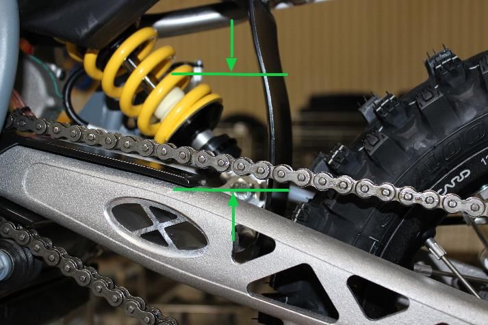
Optional Components
Weight of Rider    Fork Spring             Shock Spring
      (lb) 70 lb   0.24 kg/mm          38.5 N/mm (220 lb/in)
Less than
                   KCC63724              SCC60220P (red)
                   0.24 kg/mm           42 N/mm (240 lb/in)
   70 - 80 lb
                   KCC63724             SCC60240P (white)
                   0.26 kg/mm           45 N/mm (260 lb/in)
   80 - 90 lb
                   KCC63726          SCC60260PY stock (yellow)
                   0.28 kg/mm           49 N/mm (280 lb/in)
  90 - 100 lb                          SCC60280PG (gold)
                   KCC63728
                                             Ohlins
                                        53 N/mm     # lb/in)
                                                 (300
Greater than 100                         00281-44/50 L078
                                          SCC60300 (red)

                                 7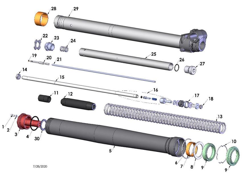
Specifications - Torque Values
                                    Torque Value               Note or
        Fastener                                                            Size & Remarks
                            ft-lb      in-lb      Nm           Loctite TM
Cylinder head nuts            9         110       12                        M6 x 1.0
Cylinder nuts                22         265       30                        M8 x 1.25**
Crankcase bolts               9         110       12                        M6 x 1.0
PV Cap Screws                 3          35        4                        M5 x 0.8
Exhaust Flange               4.5         53        6                        M6 x 1.0
Spark plug                  (SP)       (SP)      (SP)                       M14 x 1.25
Stator bolts                 2.1         25       2.8          243 blue     M5 X 0.8
Stator cover bolts           1.7         20       2.3                       M4 X 0.75
Clutch cover bolts           5.8         70       7.9                       M6 X 1.0
Clutch nut                   40         480       54           243 blue     M10 x 1.25
Crank drive nut              33         400       45           243 blue     M10 x 1.25
Front axle bolt              33         400       45                        M20 x 1.0
Front axle pinch bolt        8.8        106       12                        M6 X 1.0
Fork guard alum bolts         6         88           8        Moly lube     M6X1, ALUM
Front brake rotor            7.4       88.5         10                     M6 x 1.0
Engine mount bolts           22        265          30                     M8 X 1.25
Swingarm pivot               21        250          28                     M12 X 1.5
Intake manifold bolts        4.6        55          6.2                    M6 X 1.0
Rear axle                    21        250          28                     M14 X 1. 5
Rear sprocket                21        250          28                     M7 X 1.0
Rear brake rotor             7.4       88.5         10        243 blue     M6 x 1.0
Rear brake banjo bolts       11        132          15                     M8x1.25
Rear brake pad bolts          3         35           4       Retainer clip M5 x 0.8
Shock bolt                   35        420          47        243 blue     M10 x 1.5
Triple clamp bolt (top)       8         90          10                      M8 x 1.25
Steering stem pinch
                             9.5       115          13                      M8 x 1.25
bolt
Triple clamp bolts            6         72           8                      M6 x 1.0
(bottom)
Lever pivot bolts              2.1        25         2.8        243 blue     M5 x .8
Fork cap                       15        177          20
Fork Damper Nut                11        133          15
Ignition rotor nut             33        400          45        243 blue     M10 x 1.25
Spoke nipple – front           3.7        44           5
Spoke nipple - rear            4.5        53           6
   ** Use a ‘crows foot’ attachment oriented 90° to the torque wrench
   (SP) To apply the proper torque to the spark plug when inserting, one must first screw
   the spark plug in until the metal gasket ring causes resistance and then turn another 1/8
   to ¼ turn.

                                               8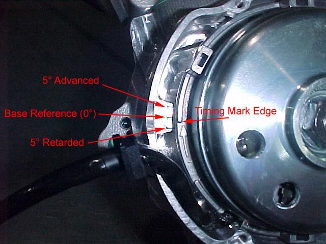
Break-In Procedure
Your Cobra CX65 is a close-tolerance high performance machine and break-in
time is very important for maximum life and performance. The CX65 can be ridden
hard after the first ½ hour break-in time.

Cobra recommends Spectro Platinum SX2 premix oil with high octane pump gas
mixed at 40:1.

CAUTION:
Failure to use proper fuel, oil, or fuel/oil mixture may result in premature engine
wear or damage to the machine.

Adhering to the following break-in schedule will result in long lasting high
performance machine.
• Start bike on stand
• First 5-minute period, operate the bike on the stand with a combination of idle
     and high RPM operation. (avoid prolonged high RPM but spin the rear
     wheel good at least once or twice per minute)
• Allow bike to cool
• Ride for 15 minutes, maximum (avoid prolonged high RPM operation and
     avoid abusing the clutch).
• Cool and inspect bike for loose fasteners.
• Check & retighten wheel spokes
• Next ½ hour of operation, avoid prolonged operation at Wide Open Throttle.
• After 1 hour of operation
     o    Check for loose bolts and nuts on the bike and retighten as necessary
          (proper toque values are listed under Specifications).
     o    Clean the carburetor bowl.
     o    Change the transmission / clutch lubricant.
• After 8 hours of operation
     o    Change the fork oil.
     o    Have a Certified Cobra Mechanic change the shock oil.
• Your bike is now ready for the highest level of competition!

                                        9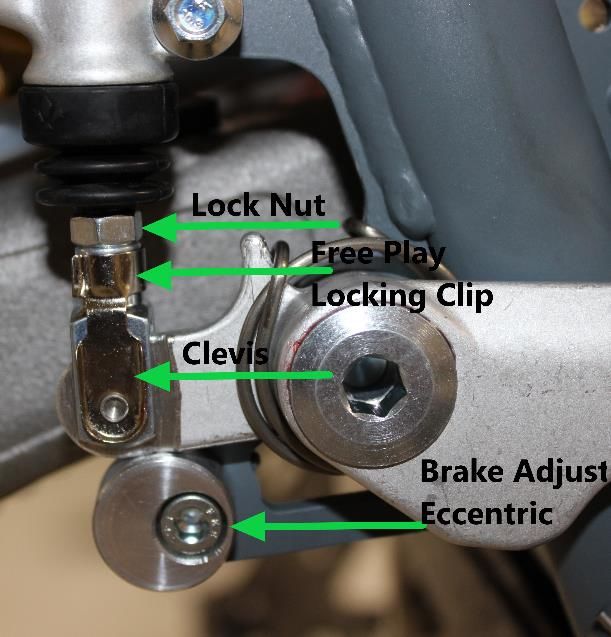
Starting Procedure
Before starting the machine inspect the following:
•    Check for proper tire pressure in both tires.
•    Observe the chain tension and adjust if necessary.
•    Observe the coolant level and fill if necessary.
•    Verify that the chain rollers and sliders do not have improper wear.
•    Verify that the handlebars are tight.
•    Check the throttle for smooth operation and sound closing.
•    Check for loose bolts and nuts, and re-torque as necessary.
•    Verify that the air filter is clean and properly saturated with oil.
•    Insure that the fuel tank contains an adequate volume of fuel / oil mixture to
     complete the distance required.
•    Turn the fuel on by rotating the fuel petcock lever to the vertically downward
     position.

CAUTION:
For best results from your Cobra Motorcycle use only the recommended fuels.
‘Race’ fuels can be used, however, they are not required with the stock engine,
and the engine will require addition attention to maintain proper jetting as
weather condition change throughout the day.

Always wear a helmet and other protective riding gear.

When your pre-ride inspection is complete the bike may be started. For a cold
engine follow this procedure.

1.   Place the motorcycle on a stand of sufficient strength that positions the
     motorcycle in a level upright position with the rear wheel off the ground.
2.   Engage the choke by pulling out on the choke button until it stops.
3.   Kick start the engine.
4.   Rev the engine in short spurts, turning the throttle no more than 1/4 open
     until the engine will run without the choke.
5.   Verify a functional engine shut-off switch by shutting off the engine.
6.   Restart the engine and proceed with riding when the engine is sufficiently
     warm (i.e. the side of the cylinder is warm to touch).

CAUTION:
Never rev an engine full throttle when it's cold or slightly warmed up. This may
lead to premature wear of engine components or complete cold seizure of the
engine.

CAUTION:
Cobra recommends that you tell your child to take it easy the first couple of
minutes in practice until the engine comes up to full operating temperature.

                                        10
Maintenance
It is important that you adhere to this maintenance schedule so as to promote the
longevity of your Cobra Motorcycle.
Tips
1. Cobra lubricants:
a. Spectro Golden SAE 80 Gear Lube is the recommended
transmission & clutch case lubricant.
b. Spectro Platinum SX2 oil is the recommended premix oil:
2. Fill your transmission only with the recommended amount of oil. Overfilling
may lead to premature seal failure.
3. The cylinder base gasket has been ‘fitted’ for your engine. See the service
section of this manual for instructions how to properly size a base gasket
during an engine rebuild.
4. Evaluate the bikes jetting only after it has been warmed up to race
temperatures.
5. A properly maintained machine is safer, faster, and more fun to ride.
6. New chains will stretch on first use. Never install a new chain prior to a
race. Always ‘break’ them in during practice.
7. Your Cobra Motorcycle has a 10-digit VIN (Vehicle Identification Number).
The first three digits indicate the model while the sixth and seventh
indicates the model year.
a. Example, CCXxx17xxx is a 2017 CX65.
Schedule
• Prior to each ride
o Check the air filter (clean and re-oil as necessary).
o Insure the smooth operation of the throttle cable (throttle soundly
‘clacks’ shut).
o Check for frayed strands of the throttle cable inside the throttle housing
and replace if necessary.
o Check for adequate tire pressures and adjust if necessary.
o Check all nuts and bolts for proper torque and re-torque if necessary.
o Check drive chain for
▪ Proper tension and adjust if necessary.
▪ Adequate lubrication and lubricate if necessary.
o Insure that the ignition stator and rotor are clean and dry.
o Check the frame for cracks in the metal or cracks in the paint that
might indicate that the metal has been stressed beyond its safe limits.
Replace or get properly re-welded as necessary.
o Check the spokes for tightness and adjust if necessary.
o Check the rims and hubs for signs of stress, like cracks around the rim,
spokes and hub.
o Equalize the pressure in the forks with atmosphere.
o Check for adequate brake operation and pad thickness
11• Every 2 hours of operation
o Replace the transmission oil.
o Check spoke tension
• Every 10 hours of operation
o Replace the fork oil.
o Have the shock oil replaced by a Certified Cobra Mechanic
• Every 15 hours
o Replace piston rings
▪ Inspect piston for wear and cracks.
o Clean the power valve (no adjustment necessary)
o Inspect the power valve cable.
CAUTION:
If you ever need to weld anything on the bike, disconnect the spark plug cap,
unplug the ignition, disconnect the kill switch, scrape the paint bare near the area
to be welded and put the ground clamp as close to the area to be welded as
possible.
Be sure the fuel tank and carburetor have been removed and safely located
away from the welding process.
The frame is a combination of HSLA steel and 4130 Chrome Moly and it is
important to weld it with the proper rod and heat settings set as light as possible.
Cobra recommends replacing the frame with a new one if the old one becomes
damaged. Use ER70S6 filler if welding on the frame.
Replacing Transmission / Clutch Lubricant
Tools needed:
• 18 oz, of Spectro Golden SAE 80 Gear Lube
• 8 mm Allen wrench
CAUTION:
General automotive motor oil has frictional modifiers
which will cause premature wear and failure of the
clutch.
Procedure:
1. Begin this procedure with a bike that has been
ridden more than 5 minutes but less than 10
minutes. It is desired to have the engine warm
enough so that the oil is ‘runny’ but not so hot that there is risk of being
burned by the engine or the oil.
Hot oil and hot components on the motorcycle may cause burns.
122. Lean the bike against something or set on stand with oil drain hole.
3. Using an 8mm Allen wrench, remove the oil drain bolt located on the right
side of the engine, on the clutch cover, near the brake lever (See Figure 1).
NOTE: You may need to adjust the brake pedal (up or down) to gain access to
the drain bolt.
4. After it has drained, reinstall the bolt being sure that the rubber gasket is in
place. Torque to 11 Nm (8 ft-lb).
5. Remove oil fill plug with an 8mm Allen wrench.
6. Carefully pour 16 oz (470 ml) of transmission oil into the oil fill opening.
7. Reinstall the oil fill plug making sure the rubber gasket is in place.
NOTE: Filling after an engine rebuild required additional transmission fluid. If the
engine is completely flushed of oil, refill with 18 oz (530ml).
Always capture and dispose of used oil properly (all auto parts stores accept
used oil). Dumping oil on the ground is illegal, inconsiderate, and can get you
disqualified from a race weekend quicker than cutting the track.
Chain adjustment
Tools required for chain adjustment
• 22 mm wrench or socket
• 2 - 11 mm open-end wrenches
1. Make sure that the rear wheel is aligned
properly.
2. For proper adjustment, the chain should
have 35 mm free movement just behind
the chain block with no load on the bike
(Figure 2) Figure 2
CAUTION: Sit on the bike and verify that the chain has
a minimum of 12mm (1/2”) free movement when the
chain is at its tightest point.
3. If the chain requires adjusting, loosen the axle
with a 22mm wrench, and loosen the jam nut with
an 11mm wrench. Tighten the chain by rotating
the adjustor bolts clockwise (CW) or loosen the
chain by rotating the adjustor bolts (CCW).
4. Put a rag between the sprocket and chain, and
roll the wheel backward to pull the chain adjustor
blocks tightly against the adjustor bolts (Figure 3).
Figure 3
135. Retighten the axle bolt to 25 ft-lb (34 Nm).
6. Retighten the adjustor jam nuts.
CAUTION:
Always check rear brake adjustment and free-play after adjusting the chain.
Lever Adjustment
Tools required for chain adjustment
• 4mm Hex Wrench
• 8mm Open End Wrench
For lever position adjustment use a 4mm
hex wrench and an 8mm open end wrench
to adjust the socket head cap screw
between the lever and the bars.
CAUTION:
The small set screw in the master cylinder housing controls freeplay/clearance
between the piston and the roller. Improper adjustment of this screw will promote
brake or clutch failure. This scew is preset at the factory. If it requires asjustment
over time (as the screw tip makes an indentation in the aluminum) set it so that
there is a minimal .001" (.001mm) clearance between the roller and the head of
the piston (see figure).
Rear Brake Maintenance
CAUTION:
Too little brake pedal free-play will allow the brake pads to drag causing the pads
to wear prematurely and possible engine component failures. Too much free-play
will not allow the rider to apply the brakes quickly.
1. Set pedal height/position first, then
2. Set pedal free play.
Brake pedal height can be adjusted with the bolt and eccentric located under the
rear of the brake pedal. The free-play is adjusted with the adjustable plunger on
the end of the brake pedal.
CAUTION:
Use only DOT 4 compatible brake fluid
14Setting rear brake pedal position:
1. Loosen the Cap Screw in the Eccentric (5mm Allen wrench).
2. Rotate the eccentric so that the lever is comfortably reachable in both:
a. Standing riding position, and
b. Sitting riding position.
3. Tighten Cap Screw (5 mm Allen
wrench).
CAUTION:
Adequate pedal free play is required so that the
brake pads do not drag on the rotor.
Make sure that the free play locking clip is
installed such that one must push forward,
toward the front of the bike, to remove.
Otherwise the clip is apt to come undone while
riding.
Figure 2b
To adjust freeplay (see figure 2b):
1. Loosen the lock nut (10mm).
2. Undo the free play locking clip from around the brake adjustor (plunger),
with your hand by pushing it forward.
3. Slide the pin of the locking free play locking clip from the brake lever
4. Adjust as needed by rotating the clevis on the end of the adjustor
(plunger).
NOTE: Turning the clevis Clockwise will lengthen the adjustor (plunger),
removing free play from the system, and turning the clevis Counter-Clockwise will
shorten the adjustor (plunger) adding free play to the system.
15Air Filter Cleaning
Tools recommended for air filter maintenance:
• 5 mm hex key (Allen)
• Foam filter oil
1. Removed seat with the 5mm hex key.
2. Unhook the air filter wire from its perch
3. Carefully remove the air filter and frame out the top
of the airbox making sure not to dislodge any dirt
into the intake tract.
4. Clean the filter in a nonflammable solvent to remove the filter oil.
Do not clean the air filter with gasoline or other highly volatile petroleum product.
Diesel fuel, mineral spirits, or kerosene would be preferred but caution should still
be taken.
5. Clean the filter in hot soapy water to remove all dirt
particles.
6. Allow it to dry thoroughly.
7. Saturate with filter oil and remove excess.
NOTE: It is very important to keep the air filter clean and
properly oiled with high quality water-resistant foam filter
oil. Apply oil consistently because varied amounts of oil
will affect carburetor jetting.
8. Reinstall the filter assembly by pushing it down and
forward into the airbox making sure the lip of the filter
cage is properly seated into its receptacle (figure 5). Figure 5
Reinstall the air filter cap and holding wire.
CAUTION:
Double check to insure that the filter is pushed in tight at the bottom
NOTE: Make sure you change or clean your filter after each moto. We
recommend carrying multiple filters in your toolbox, one for each practice session
and moto.
Fork Maintenance
Cobra strongly recommends that a professional service technician conduct all
internal maintenance other than changing springs and oil. This will help to ensure
safe and consistent operation.
16For routine maintenance, the chart below provides suggested service intervals
for common procedures:
Each Ride 10 hours 20 hours As Needed
Bleed excess air X
Change Oil X
Change
X
Seal/Swiper
Change Bushings X
Fork Air Bleeding
Tools required
• 3mm hex key (Allen wrench)
During normal operation, both fork legs will build up air pressure. This pressure
acts as an additional spring so it must be bled on a regular basis to maintain
consistent suspension operation. Before each ride, loosen the socket head cap
screw located at the front of each fork cap far enough so that any excess
pressure in the leg is relieved. After excess air is bled off, retighten the screw to 5
in-lb. Be careful not to lose or damage the sealing ring that is located under the
head of each bleed screw.
Fork Oil Replacement
Tools required
• 37mm Fork Cap Tool (MCMUTL37)
• 22mm closed-end wrench or socket
• 14mm open-end wrench
• Drift punch (12mm OD x 300mm long (1/2” x 12”))
• 5 & 6 mm hex key (Allen wrench)
• Mallet
• 5 wt. Spectro fork oil
Disassembly procedure
1. Remove the front wheel.
a. Loosen the brake-side axle pinch bolts (5mm hex key)
b. Carefully remove the brake side axle cap using a closed-end wrench to
protect the cap from damage. (22mm wrench)
c. Loosen the non-brake side axle pinch bolts (5mm hex key)
17d. Using the drift punch (a long 3/8 socket extension will also work),
remove the axle from the fork lugs by placing the punch inside the
hollow axle and tapping lightly on the exposed end with the mallet.
e. Carefully slide with wheel downward out of the brake caliper.
2. Remove the brake caliper from the fork leg (6mm hex key).
3. Loosen the fork caps (Cobra 37mm Fork Cap Tool).
4. Remove the fork legs from the triple clamps (5mm hex key).
5. One leg at a time:
a. Remove the fork cap from the fork tube.
b. Lower the fork tube to expose the fork spring.
c. Pull the fork spring down from the fork cap to expose the damper rod
lock nut. Secure this nut using a 14mm wrench.
d. With the 14mm wrench on the damper rod nut, use the 37mm fork cap
wrench to free the fork cap from the damper rod.
e. Remove the 14mm wrench and allow the damper rod to fall into the
cartridge tube.
f. Remove the fork spring.
g. Invert the fork to allow the oil to drain. Pump the damper rod assembly
several times to help any excess oil trapped in the cartridge to drain.
Assembly procedure
1. Completely collapse the outer fork tube onto the stanchion tube.
2. Pump the damper rod up and down slowly to help the assembly fill with oil.
3. Install the fork spring.
4. Use a flexible retrieving tool to pull the damper rod up through the fork spring
and thread the damper rod into the fork cap.
CAUTION:
Ensure that the fork cap is completely threaded onto the damper rod before it
makes contact with the lock nut.
5. Pull the fork spring down from the cap and torque the damper rod lock nut to
15 N-m (11ft-lb) with a 14mm wrench.
CAUTION:
The damper rod is hollow and will break if the nut is over tightened.
6. Ensure that the fork cap O-ring is in good condition, Use the 37mm fork cap
wrench to secure the fork cap to the fork outer tube. Torque the fork cap to 20
Nm (15 ft-lb).
7. Pump the fork leg several times to verify that it operates smoothly.
8. Install each leg back into the triple clamp. Torque each pinch bolt to 11N-m (8
ft-lb) making sure both legs are set to the same height in the clamps.
9. Reinstall the brake caliper.
10. Reinstall the front wheel.
1. Install axle through non-brake side fork lug and wheel hub
182. Slide wheel spacer over axle taking care to ensure that the internal
O-ring is in place.
3. Continue sliding axle through brake-side lug and reinstall axle cap
(6 ft-lb, 8 Nm)
4. Lightly torque all four axle pinch bolts
5. Drop the bike onto the ground, engage the front brake, and push up
and down on the handlebars several times to ensure that the front
forks and the front wheel are properly aligned with each other.
6. Apply final torque to all four axle pinch bolts (7.4 ft-lb, 10 Nm)
Ignition Timing
The ignition timing value for the CX65 is 0° retarded from the standard base
reference (0°). This can be verified by removing the ignition cover and looking as
shown in the figure below.
The center mark on the cases is the standard base reference timing mark (0°),
and the other two large marks are 5° advanced and retarded. The small timing
marks between 0 & 5° is 2.5°.
To change the timing, one must remove the flywheel with Cobra 65 flywheel
puller # MCMUTL05. After the flywheel has been removed, the timing can be
adjusted by loosening the stator bolts and rotating the stator to the desired
position.
19Cable Ties
There is one location where we have used reusable frame mount cable ties this
year on the CX65.
To disconnect these cable ties, use a screw driver as shown and push down on
the short tab. The tab will be hidden from view by the cable tie strap.
20Parts
Parts – Air Box & Inlet System
Air Box & Inlet
REF # PART # DESCRIPTION
1 RCC60007 AIRBOX
2 TCC60008 MUD FLAP
TCC60125 BRACKET - MUDFLAP
3 HCSP0004 SCREW – PLASCREW
4 MCKGHO03 CLAMP, AIR BOOT TO AIR BOX
5 RCC60002 AIR FILTER
6 RCC60003 AIR FILTER CAGE
7 RCC60004 AIR FILTER WIRE
8 RCC60014 AIR BOOT, CARB TO AIRBOX
9 RCC60006 AIR FILTER CAP
10 ECC60006 REED ASSEMBLY
11 ECC60007 INLET MANIFOLD
12 HCBC0625 M6x25mm SOCKET HEAD CAP SCREW
HCWF0601 M6 FLAT WASHER
13 MCC60003 CLAMP, MANIFOLD TO CARB
14 ZCC60021 GASKET REED
15 RCR60026 CARBURETOR 26mm MIKUNI
16 MCMUCL04 HOSE CLAMP 8mm
17 FCMU0026 FUEL LINE
18 TCC60125 MUD FLAP BRACKET
18 ECC60014 REED PETALS – REPLACEMENT
21Parts – Bars and Controls
Bars and Controls
REF # PART # DESCRIPTION
1 FAC60023 HANDLEBARS – PROTAPER CX65
2 TCC60035 GRIPS – PROTAPER (SET OF TWO)
3 FCMU0066 THROTTLE ASSEMBLY
FCMU0042 TUBE – THROTTLE
4 FCPW0004 CABLE COVER
5 FCMU0021 THROTTLE COVER
6 RAC60001 THROTTLE CABLE
7 CCC60022 MASTER CYLINDER ASSEMBLY – MAGURA – W LEVER
8 FCMU0033 KILL SWITCH ASSEMBLY
9 TKMU0404 BAR MOUNT KIT, SHORT (1 REQ’D) STANDARD
9A TKMU0403 BAR MOUNT KIT, TALL (1 REQ’D)
10 HCBC1035 M10X35mm SOCKET HEAD CAP SCREW (2 REQ’D)
11 HCNL1001 M10 LOCK NUT
12 HCBC0806 M8 X 30 SCOCKET HEAD CAP SCREW (4 REQ’D)
13A CCC60034 LEVER – CLUTCH – MAGURA
13B CKC60004 LEVER ASSY – BRAKE - CARD
14 BAC60010 MASTER CYLINDER ASSEMBLY - BRAKE - WITH LEVER
15 HCBC0812 M8 X 12 SHCS - LOW PROFILE (2 REQ’D)
MCMU0001 PAD – CROSS BAR
ACCESSORY BKC60015 REBUILD KIT – MASTER CYLINDER - BRAKE - ZL
ACCESSORY CCC60038 REBUILD KIT – CLUTCH MASTER CYLINDER - MAGURA
22Parts - Carburetor
Carburetor
REF. # PART # DESCRIPTION
1 RCR60026 CARBURETOR 26MM MIKUNI
2 RCC60017 FLOAT BOWL CHAMBER
4 RCMU0271 NEEDLE VALVE & SEAT ASSY
6 SEE BELOW MAIN JET
9 RCEX0026 NEEDLE JET STOCK 5L14
10 SEE BELOW PILOT JET
11 RCC60013 GASKET, FLOAT BOWL
15 RCEX0016 SPRING IDLE ADJUST SCREW
16 RCEX0015 IDLE ADJUST SCREW
17 ZCDCOR01 O’RING BOWL PLUG
18 RCEX0012 FLOAT BOWL SCREW
20 RCC60025 SLIDE
21 RCC60016 SLIDE STUFFER
22 RCMU0277 CLIP – NEEDLE
24 RCEX0005 ADJUSTER
25 RCEX0006 LOCK NUT
27 RCC60026 CHOKE ASSY
33 RCEX0013 AIR ADJUSTING SCREW
34 RCEX0014 SPRING – AIR ADJUST SCREW
RCMU0415 CABLE ADJUSTER CAP (RUBBER)
NOT
RCC60021 AIR SCREW O-RING
SHOWN
RCC60020 AIR SCREW WASHER
PILOT JET MAIN JET
30 RCEX0030 190 RCMU0190
32.5 RCEX0032 195 RCMU0195
35 RCEX0035 200 RCMU0200
37.5 RCEX0037 205 RCMU0205
40 RCEX0040 210 RCMU0210
42.5 RCEX0042 215 RCMU0215
45 RCEX0045 220 RCMU0220
47.5 RCEX0047 230 RCMU0230
50 RCEX0050 240 RCMU0240
52.5 RCEX0052 250 RCMU1250
55 RCEX0055 260 RCMU1260
57.5 RCEX0057 270 RCMU1270
60 RCEX0060 280 RCMU1280
290 RCMU1290
300 RCMU1300
310 RCMU1310
23Parts – Clutch – Master Cylinder
Clutch – Master Cylinder
REF# PART # DESCRIPTION
1 CCC60022 MASTER CYLINDER – CLUTCH – MAGURA
2 CCC60033 CLAMP W/PIN – CLUTCH MASTER CYLINDER
4 CCC60039 COVER – CLUTCH LEVER PIVOT - MAGURA
5 CCC60034 LEVER – MAGURA CLUTCH
6 CCC60035 SCREW & NUT – CLUTCH LEVER – MAGURA
8 CCC60037 COVER – CLUTCH RESERVOIR – MAGURA MINERAL OIL
9 CCC60036 PUSH ROD & BELLOWS - CLUTCH LEVER - MAGURA
10 CCC60038 REBUILD KIT – CLUTCH MASTER CYLINDER 9.5
11 BCMU0017 FERRULE – COMPRESSION FITTING
12 BCMU0020 FITTING – THREADED CLUTCH LINE END
13 BCMU0021 COVER – FOR SLEEVE NUT
14 CCC60041 LINE – CLUTCH - REPLACEMENT KIT – FORGED COVER
(LINE & 2 FERRULES)
24Parts – Coolant System
Coolant System
REF # PART # DESCRIPTION
1 FCC60060 RADIATOR W/CAP - CX65
2 FCMU0052 CAP – 1.3 BAR
3 MCMUCL05 HOSE CLAMP 11-20 UNIVERSAL
4 FCKG0214 HOSE – OVERFLOW
5 FCDC0009 RADIATOR LOUVER-CX65
6 HCPP0001 PUSH PIN – REMOVABLE
7 HCCN0000 5mm EXTRUDED "U" NUT
8 ECC60034 HOSE RADIATOR UPPER
9 MCMUCL07 CLAMP – HOSE - RADIATOR MEDIUM (4 REQ’D)
10 ECC60192 HOSE – RADIATOR BOTTOM
12 MCMUGR03 GROMMET RADIATOR (2 REQ’D)
13 HCWF1478 6mm WASHER 22mm OD BLK ZINC (2 REQ’D)
14 HCBF0620 M6X20mm FLANGED HEX - 8mm HEAD (2 REQ’D)
15 HCBH0805 M8 X 12mm HEX HEAD BOLT
16 HCWC0000 WASHER – COPPER
ACCESSORY ECR60020 HOSE SET SILICONE - RED
ACCESSORY ECR60021 HOSE SET SILICONE - BLUE
TOOL MCMUTL16 TOOL – RAD CAP REMOVALParts – Electrical System
Electrical System
REF # PART # DESCRIPTION
1 ICC60014 STATOR – POWER VALVE CX65
2 HCBT0516 M5X16mm TORX HEAD SCREW (3 REQ’D)
3 HCWF0501 5mm FLAT WASHER (3 REQ’D)
4 ICC60007 ROTOR OUTER STYLE CX65
5 ICMU0012 WOODRUFF KEY (NOT SHOWN)
6 HCWF0010 10mm FLAT WASHER
7 HCNS1001 M10 NUT
8 ICC60017 CDI UNIT – POWER VALVE CX65
9 ICMU0035 MOUNT – CDI
10 ICC60005 COIL DIGITAL 65
11 HCBC0516 M5X16mm SOCKET HEAD CAP SCREW – COIL MOUNTING (2 REQ’D)
12 HCWF0501 5mm WASHER – COIL MOUNTING (2 REQ’D)
13 HCCN0000 5mm EXTRUDED “U” NUT – COIL MOUNTING (2 REQ’D)
14 ECMU0033I SPARK PLUG
15 FCMU0033 KILL SWITCH ASSEMBLY
16 ECC60166 COVER – IGNITION
17 HCBC0402 M4X35mm SOCKET HEAD CAP SCREW – COVER MOUNTING (3 REQ’D)
NOT SHOWN FCMU0030 COVER – KILL SWITCH SCREW
ACCESSORY ICMU0016 SPARK PLUG CAP 5K Ω
ACCESSORY MCKGGR00 GROMMET WIRE PROTECTION (2 PLACES)
TOOLS MCMUTL05 PULLER – FLYWHEEL
TOOLS MCMUTL19 HARNESS – DIAGNOSTIC BREAKOUT
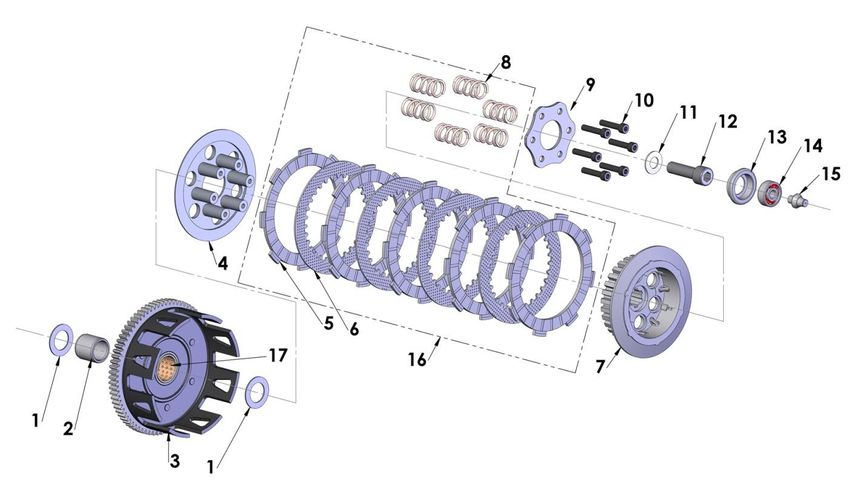
26Parts – Engine Clutch
Clutch Components
REF. # PART # DESCRIPTION
1 ECDC0063 CLUTCH WASHER (2 REQ’D)
2 ECDC0064 CLUTCH BUSHING – INNER / STEEL
3 EAEX0003 CLUTCH BASKET ASSEMBLY (INCLUDES ECDC0167)
4 ECDC0066 CLUTCH PRESSURE PLATE
5 ECDC0068 CLUTCH DISC-FRICTION – (5 REQ’D)
6 ECDC0067 CLUTCH DISC-STEEL – (4 REQ’D)
7 ECDC0069 CLUTCH HUB
8 ECDC0070 SPRING, CLUTCH – (6 REQ’D)
9 ECDC0071 PLATE, CLUTCH SPRING
10 HCBC0525 M5X25mm SOCKET HEAD CAP SCREW (6 REQ’D)
11 ECDC0030 SPRING WASHER – CLUTCH
12 HCBF1030 M10X30mm FLANGE HEAD BOLT
13 ECDC0019 CLUTCH BEARING SEAT
14 ECDC0018 BEARING, CLUTCH THROW OUT
15 ECC60190 PUSH ROD – CLUTCH 2015
16 CKMU0001 CLUTCH KIT INCLUDING – SPRINGS, STEELS AND FIBERS
17 ECDC0167 CLUTCH BUSHING – OUTER / BRONZE (REPLACEMENT)
ACCESSORY CKC60002 CLUTCH BASKET REPLACEMENT KIT
27Parts – Engine – Clutch / Kick Cover
Clutch / Kick Cover Components
REF. # PART # DESCRIPTION
1 ECC60178 COVER – CLUTCH
2 ZCC60016 GASKET – CLUTCHCOVER
3 HCBC0602 M6X20mm SOCKET HEAD CAP SCREW (12 TOTAL REQ'D)
(7 REQ’D FOR CLUTCH COVER, 5 REQ'D FOR CLUTCH CAP)
4 HCBC0625 M6X25mm SOCKET HEAD CAP SCREW (2 REQ’D)
5 EAMU0011 LEVER ASSEMBLY – KICKSTARTER
6 ECMU0250 WASHER – KICK LEVER
7 HCFH0616 M6X16mm FLAT HEAD CAP SCREW
8 ECDC0078 SEAL – KICKSTARTER
9 ECMU0168 OIL FILL PLUG, ALUMINUM
10 ZCMUB014 O-RING – OIL FILL PLUG
11 ECC60179 CAP – CLUTCH - W/SLAVE CYLINDER
12 ZCC60013 O-RING – CLUTCH CAP
13 CCC60005 PISTON – CLUTCH SLAVE CYLINDER
14 CCEX0009 BALL – CLUTCH ENGAGEMENT
15 CCC60007 BELLOWS – CLUTCH SLAVE
16 CCC60006 SPRING – SLAVE RETURN
17 ZCMUOR35 O-RING – SLAVE PISTON – MINERAL OIL
18 BCMU0017 FERRULE – COMPRESSION FITTING
19 BCMU0020 FITTING – THREADED CLUTCH LINE END
20 BCMU0021 COVER – RUBBER CLUTCH LINE END
21 CCC60040 LINE – CLUTCH REPLACEMENT
22 BCMU0018 FITTING – BLEED, CLUTCH LINE
23 CCC60030 CLAMP – CLUTCH LINE
24 BCC60034 CAP - BLEED SCREW
ACCESSORY EKMU0002 PIVOT SPRING, BALL AND SET SCREW KIT – KICK STARTER
28Parts – Engine – Ignition Side
Ignition Side Engine Components
REF. # PART # DESCRIPTION
1 ECC60166 IGNITION COVER
2 HCBC0402 M4X35mm SOCKET HEAD CAP SCREW (3 REQ’D)
3 HCNS1001 M10 NUT
4 HCWF0010 10mm FLAT WASHER
5 ICC60007 ROTOR PVL OUTER STYLE
6 ICC60014 STATOR PVL DIGITAL – POWER VALVE CX65
7 HCBT0516 M5X16mm BUTTON HEAD TORX (3 REQ’D)
8 HCWF0501 5mm WASHER FLAT (3 REQ’D)
9 ECDC0024 SEAL, CRANKSHAFT
11 EKC62015 ENGINE CASE SET W/B&S CX65 – 2015 AND NEWER
12 HCBH0602 M6X25mm HEX HEAD BOLT
13 ECR60015 SHIFTER LEVER – ALUMINUM
14 ECDC0026 SEAL, SHIFTER
15 ECMU0020 BEARING, SHIFTER SHAFT
16 ECKGSR03 SNAP RING – OUTPUT - COBRA
17 PCKG00xx xx DENOTES TEETH – RANGE OF TEETH (13-16)
18 ECDC0009 SPACER, SPROCKET
19 ZCMUOR21 O-RING, SPROCKET SPACER
20 ECDC0025 SEAL, OUTPUT
29Parts – Engine – Kick Mechanism & Water Pump
Kick Mechanism
REF. # PART # DESCRIPTION
1 EKC62015 CRANKCASE – SET WITH BEARINGS & SEALS
2 ECDC0033 GEAR, KICKSTART
3 ECDC0035 SNAP RING, EXTERNAL 12mm
4 ECC60203 SHAFT, KICK STARTER – THREADED
5 ECC60201 GEAR – KICK RAMP - NO ARM
6 ECDC0042 SPRING, KICKSTART RAMP
7 ECDC0043 WASHER, KICKSTART BACKUP
8 ECDC0036 SNAP RING, EXTERNAL 16mm - SPRING RET.
9 ECC60067 SPRING – KICK RETURN CX65
10 ECC60202 SPACER – KICK SPRING CENTERING - 2015
11 ECDC0032 GEAR, KICK START IDLE
12 ECDC0037 SNAP RING, EXTERNAL 15mm
13 ECMU0174 HOLDER – SPRING 20MM
14 HCFH0616 M6 X 16 FLAT HEAD SCREW
15 HCBB0403 M4 X 8 BUTTON HEAD
16 ECKG0073 IMPELLER – WATERPUMP
17 ECC60173 SHAFT – WATERPUMP
18 ECDC0051 PIN – DOWEL
19 ECC60175 SEAL – WATERPUMP
20 ECC60174 BEARING – WATERPUMP
21 ECC60176 SNAP RING – 8MM SHAFT
22 ECC60177 HOUSING – WATERPUMP
23 ECC60172 GEAR – WATERPMP DRIVE
24 HCBC0601 M6 X 16 SOCKET HEAD CAP SCREW (3 REQ'D)
25 ECMU0233 FITTING, VENT HOSE
26 ECMU0534 VENT HOSE
27 ZCMUOR07 O’RING – WATER PUMP
28 ECC60200 RAMP W STOP - KICK MECHANISM
30Parts – Engine – Shift Mechanism
Shifting Components
REF # PART # DESCRIPTION
1 EAC60017 SHAFT – SHIFTER W/ PIVOT PLATE
2 ECDC0055 SPRING – SHIFTER PLATES
3 EAC60018 PLATE – SHIFT SLIDING
4 ECC60124 SPRING – SHIFTER SHAFT CENTERING
5 ECC60146 BUSHING – SPRING CENTERING
6 HCBC0806 M8X30mm SOCKET HEAD CAP SCREW (BLACK OXIDE)
7 ECC60189 CASSETTE – SHIFT (W/O PINS)
8 ECDC0051 DOWEL – SHIFT CASSETTE (6 & 1 REQ’D)
9 ECDC0022 BEARING – SHIFT DRUM
10 ECDC0035 CLIP – ARM RETAINER
11 ECMU0545 ARM ASSY – SHIFT FOLLOWER
12 ECMU0546 SPRING – SHIFT FOLLOWER ARM
13 ECC60096 PIVOT – SHIFT ARM
14 HCBB1612 M6X12mm BUTTON HEAD BLACK OXIDE
15 ECMU0016 BEARING – PRIMARY SHAFT CLUTCH SIDE
16 HCNS1001 NUT – M10 X 1.25
17 ECDC0030 BELLEVILLE – LOCK WASHER - 10MM
18 ECDC0073 GEAR – CRANK DRIVE
19 ECC60198 SPACER – CRANK DRIVE GEAR
20 EKC62015 CRANKCASE – SET WITH BEARINGS & SEALS
21 ECDC0053 DOWEL – CLUTCH COVER POSITION (2 REQ’D)
22 ECC60095 PLATE – BEARING RETAINER
23 ECMU0020 BEARING – SHIFTER SHAFT
24 ECC60119 SHIM WASHER
(NOTE MEASURE SHIM TO ORDER CORRECT SIZE)
25 ECC60152 SHIM 0.2mm THICK
25 ECC60153 SHIM 0.3mm THICK
26 HCFH0512 M5 X 12mm FLAT HEAD SCREW
NOT SHOWN ECC60028 COLLAR – SWINGARM PIVOT
31Parts – Engine – Top End
32Engine – Top End
REF # PART # DESCRIPTION
1 ECC60457 CYLINDER KIT PV CX65 (INCLUDES PISTON KIT & CYLINDER)
2 ZCC60302 BASE GASKET 0.2mm THICK
2 ZCC60303 BASE GASKET 0.3mm THICK
2 ZCC60304 BASE GASKET 0.4mm THICK
2 ZCC60305 BASE GASKET 0.5mm THICK
2 ZCC60306 BASE GASKET 0.6mm THICK
2 ZCC60307 BASE GASKET 0.7mm THICK
2 ZCC60308 BASE GASKET 0.8mm THICK
3 ECC60208x PISTON KIT (x DENOTES PISTON SIZE A,B, or C)
ECC60208WP WRIST PIN – PISTON – 44.5MM CAST
4 ECC60222 SNAP RING FOR PISTON (2 REQ’D)
5 ECC60221 PISTON RINGS 44.5mm (2 PER SET)
6 ECDC0061 BEARING, WRIST PIN
7 ECC60109 STUD, CYLINDER 8mm (4 REQ’D)
8 HCNF0801 M8 FLANGE NUT (4 REQ’D)
9 ECC60107 STUD, CYLINDER 6mm (5 REQ’D)
10 ZCC60009 O-RING – GASKET LARGE PV HEAD OUTER
11 ZCMUOR05 O-RING CYLINDER HEAD MEDIUM - YELLOW
12 ECC60207 CYLINDER HEAD INSERT
13 ZCMUOR23 O-RING CYLINDER HEAD SMALL
14 ZCMUOR03 O-RING CYLINDER STUD - YELLOW (5 REQ’D)
15 ECC60149 CYLINDER HEAD OUTER
16 HCNF0601 M6 FLANGE NUT (5 REQ’D)
17 ZCMUOR07 O-RING, EXHAUST FLANGE TO CYLINDER
18 ECMU0262 FLANGE – EXHAUST
19 HCBC0601 M6X16mm SOCKET HEAD CAP SCREW (2 REQ’D)
20 ZCMOTE11 O-RINGS – PIPE TO FLANGE (2 REQ’D)
21 ZCMUOR11 O-RING – PIPE to FLANGE (1 REQ’D)
NOT ZKMUOR13 O-RING KIT – TOP END – CX65 PV
SHOWN EAC62017 COMPLETE ENGINE
33Parts – Engine – Transmission
34Transmission
REF # PART # DESCRIPTION
1 ECC60219 CRANKSHAFT CX65
2 ECR60007 BEARING – CRANKSHAFT – IGNITION SIDE
3 ECDC0024 SEAL – CRANKSHAFT (2 REQ'D)
ACCESSORY EKEX0001 ROD KIT
4 EKC62015 CASE SET – ENGINE W/B&S CX65
5 ECC60028 BUSHING - ENGINE / SWINGARM PIVOT CX65
6 ECWX0025 HOLLOW DOWEL - 8.4 x 14 x 7
Case Screws - Short HCBC0603 M6X30mm SOCKET HEAD CAP SCREW (11 REQ’D)
Case Screws - Long HCBC0604 M6X35mm SHCS (2 REQ’D) - thru the 2 hollow dowels
7 ZCC60014 GASKET – CENTER CASE
8 ECKG0031 BEARING – PRIMARY SHAFT IGNITION SIDE
9 EAC60041 PRIMARY SHAFT SUB-ASSY
10 ECC60306 GEAR – 2ND PRIMARY, 16T- INVOLUTE 3 DOG ROUND
11 ECDC0005 GEAR – 5TH PRIMARY, 23T-3 DOG ROUND
12 ECDC0003 SNAP RING - EXTERNAL 17mm (2 REQ’D)
GEAR – 3RD/ 4TH PRIMARY, 18/21T-INVOLUTE 3 DOG
13 ECC60304
ROUND
14 ECDC0002 GEAR – 6TH PRIMARY 24T – 3 DOG ROUND
SHAFT – TRANSMISSION PRIMARY (1ST GEAR), 13T -
15 ECC60301
INVOLUTE
16 ECMU0016 BEARING – PRIMARY SHAFT CLUTCH SIDE
17 ECC60070 ROD – SHIFT FORK (2 REQ’D)
18 ECC60071 SPRING - SHIFT ROD CENTERING (4 REQ’D)
19 ECDC0048 FORK – INPUT - SHIFT
20 ECDC0049 FORK – OUTPUT - SHIFT (2 REQ’D)
21 ECDC0022 BEARING - SHIFT DRUM (2 REQ'D)
22 ECC60186 DRUM – SHIFT
23 ECDC0051 PIN – DOWEL - SHIFT DRUM TO CASSETTE
24 ECKGBR01 BEARING - OUTPUT IGNITION SIDE
25 EAC60042 OUTPUT SHAFT SUB-ASSY
SHAFT – TRANSMISSION OUTPUT – INVOLUTE 4 DOG
26 ECDC0307
SQUARE
27 ECC60114 GEAR – 2ND OUTPUT, 34T – 4 DOG SQUARE
28 ECDC0017 SHAP RING - EXTERNAL 18mm (3 REQ’D)
29 ECC60323 GEAR – 5TH, OUTPUT, 28T – INVOLUTE 4LD
30 ECC60111 GEAR – 4TH OUTPUT, 30T – 4 DOG SQUARE
31 ECC60110 GEAR – 3RD OUTPUT, 31T – 4 DOG SQUARE
32 ECC60325 GEAR – 6TH OUTPUT, 26T – INVOLUTE 4LD
33 ECC60116 GEAR – 1ST OUTPUT, 37T – 4 DOG SQUARE
34 ECDC0021 BEARING – OUTPUTSHAFT CLUTCH SIDE
35 ECC60160 SHIM – TRANSMISSION .2mm THK
36 ECC60161 SHIM – TRANSMISSION .5mm THK (2 REQ’D)
ACCESSORY ECMU0040 SHIM – TRANSMISSION 0.030” (0.8mm) THICK
ACCESSORY ECMU0040T SHIM – TRANSMISSION 0.015” (0.4 mm) THIN
EAC62021 COMPLETE ENGINE
35Parts – Engine – Power Valve
Engine – Power Valve
REF # PART # DESCRIPTION
1 EAC60019 VALVE ASSY – PV - WITH LINK AND PLUNGER
2 ZCC60017 O'RING – PV COVER
3 ECC60217 SPRING – PV RETURN
4 ECC60089 COVER – PV
5 EAC60021 SOLENOID ASSY - PV
6 MCMUCL04 CLAMP – VENT HOSE
7 ECC60133 VENT HOSE
8 HCBC0501 M5X12mm SOCKET HEAD CAP SCREW (2 REQ’D)
9 MCMUCL07 CLAMP – BOOT TO COVER
10 ZCMUOR08 O-RING
11 HCBB0506 M5x 6 BUTTON HEAD CAP SCREW
12 ECC60220 SPRING – PV FACE MOUNT
13 FCC60071 SOLENOID CLAMP - PV
TOOL MCMUTL19 HARNESS – DIAGNOSTIC BREAKOUT
36Parts – Exhaust System
Exhaust System
REF # PART # DESCRIPTION
1 XCC62017 EXPANSION CHAMBER – HGS
2 XCMU0033 ISOLATION MOUNT
6mm CLIP NUT- PLASTIC/PIPE MNT (1 REQ’D FOR PIPE & 2
3 HCHA0003
REQ’D FOR SILENCER)
4 HCBF0616 M6X16mm FLANGE HEAD BOLT (2 REQ’D)
5 ZCMOTE11 O-RING – EXHAUST (2 REQ’D)
6 XCMU0005 SPRING – PIPE – SHORT
7 XCKG0009 SLEEVE – PIPE TO SILENCER
8 XAC62017 SILENCER – COBRA
9 MCMUGR03 GROMMET FOR RADIATOR (2 REQ’D)
10 TCKG0001 SPACER GENERAL ½DIA 13.2 LG (2 REQ’D)
11 TCC60016 SPACER TOP HAT (2 REQ’D)
12 HCBF0635 M6X35mm FLANGE HEX-8mm HEAD
ACCESSORY XCMU0026 SILENCER PACKING KIT
37Parts – Forks & Triple Clamps
38Forks & Triple Clamps
REF # PART # DESCRIPTION
1 KAC62013 FORK COMPLETE, BRAKE & NON-BRAKE SIDE
2 KCC60014 FORK GUARDS – PAIR (3 BOLT STYLE)
3 HCSP0610 BOLT - FORK GUARD - 6MM ALUMINUM (6 REQ'D)
4 HCBC0612 M6X12mm SOCKET HEAD CAP SCREW (2 REQ'D)
5 BCC60015 CLAMP – BRAKE LINE
6 HCNS0601 M6 NUT (2 REQ'D)
7 FAC60024 TRIPLE CLAMP BOTTOM ASS’Y (CLAMP & STEERING STEM)
8 FCC60079 TOP TRIPLE CLAMP
9 FCMU0073 BOLT – STEERING STEM
10 FCMU079 DUST COVER (1 REQ’D)
11 FCMU0044 O-RING (1 REQ’D)
12 FCC60081 SEAL RING - ORING - BOTTOM TRIP CLAMP
13 FCMU0004 BEARING – STEERING HEAD (2 REQ’D)
14 HCBC0625 M6X25mm SOCKET HEAD CAP SCREW (8 REQ’D)
15 HCBF0616 M6X16 FLANGE HEAD SCREW (4 REQ’D) FENDER MOUNT
16 HCBC0601 M6X16mm SOCKET HEAD CAP SCREW (4 REQ'D) AXLE
17 HCBC0806 M8X30mm SHCS – STEERING STEM PINCH BOLT
18 FCMU0011 RACE – STEERING HEAD BEARINGS
19 HCBF0612 M6X12 FLANGE HEAD SCREW – NUBER PLATE MOUNT
20 TCC60021 SPACER – FENDER MOUNT
ACCESSORY FKMU0008 KIT – STEERING STEM BEARINGS, RACES AND SEALS-2019
39Parts – Fork – Leg Assembly – Brake Side
Fork – Leg Assembly – Brake Side
REF # PART # DESCRIPTION
1 HCBC0408 M4X8mm SOCKET HEAD CAP SCREW (BLEED SCREW)
2 ZCKG0001 GASKET BLEED SCREW
3 KCC60044L FORK CAP
4 ZCC60011 O-RING FORK CAP
5 KCC60037 FORK OUTER TUBE
6 KCC60043 FORK OUTER WEAR RING CLIP
7 KCC60041 FORK GUIDE RING BOTTOM
8 KCC60047 FORK SEAL SPACER
9 KCC60039 FORK SEAL & SWIPER KIT - 37mm - CX65
10 KCC60066 FORK SEAL RETAINER RING CLIP
11 KCC60067 FORK BUMPER
12 KCC60064 FORK SPRING GUIDE
13 KCC63726 FORK SPRING .26 KG/MM (SINGLE)
13 KCC63724 FORK SPRING .24 KG/MM (SINGLE)
13 KCC63728 FORK SPRING .28 KG/MM (SINGLE)
14 HCNJ3824 3/8-24 JAM NUT CLASS 8
15 KCC60068 FORK SPRING GUIDE RETAINER RING CLIP
16 KAC60003 FORK DAMPER ROD ASSEMBLY
17 KCCS0018 FORK MID VALVE SEAL
18 HCNJ0601 M6 JAM NUT
19 BCKG0033 O-RING 2mm ID
20 KCC60052 FORK ADJUSTMENT SCREW TOP
21 KCC60049 FORK REBOUND ADJUSTMENT SCREW PIN
22 KCC60042 FORK SPRING PERCH
23 KCMU0013 FORK CARTRIDGE CAP W BUSHING
24 KCKG0050 FORK TOP OUT SPRING
25 KCKG0019 FORK CARTRIDGE TUBE
26 KCMU0021 O-RING FORK BASE VALVE PISTON
27 ZCKGB017 O-RING FORK BOTTOM PLUG
28 KCC60069 FORK BOTTOM PLUG
29 KCC60048 FORK ADJUSTMENT SCREW BOTTOM
30 ZCMUOR03 O-RING
31 KCC60065 FORK ADJUSTMENT SCREW BOTTOM RING CLIP
32 KCC60036 FORK GUIDE RING TOP
33 KAC60001 FORK LOWER BRAKE SIDE (NOT SOLD SEPARATELY)
34 KCC60053 FORK SPRING PAD 37MM
40Parts – Fork – Leg Assembly – Non-Brake Side
Fork – Leg Assembly – Non-Brake Side
REF # PART # DESCRIPTION
1 HCBC0408 M4X8mm SOCKET HEAD CAP SCREW (BLEED SCREW)
2 ZCKG0001 GASKET BLEED SCREW
3 KCC60044R FORK CAP
4 ZCC60011 O-RING FORK CAP
5 KCC60037 FORK OUTER TUBE
6 KCC60043 FORK OUTER WEAR RING CLIP
7 KCC60041 FORK GUIDE RING BOTTOM
8 KCC60047 FORK SEAL SPACER
9 KKC60039 FORK SEAL & SWIPER KIT – 37mm - CX65
10 KCC60066 FORK SEAL RETAINER RING CLIP
11 KCC60067 FORK BUMPER
12 KCC60064 FORK SPRING GUIDE
13 KCC63726 FORK SPRING .26 KG/MM (SINGLE)
13 KCC63724 FORK SPRING .24 KG/MM (SINGLE)
13 KCC63728 FORK SPRING .28 KG/MM (SINGLE)
14 HCNL3824 3/8-24 JAM NUT CLASS 8
15 KCC60068 FORK SPRING GUIDE RETAINER RING CLIP
16 KAC60003 FORK DAMPER ROD ASSEMBLY
17 KCCS0018 FORK MID VALVE SEAL
18 HCNJ0006 M6 JAM NUT
19 BCKG0033 O-RING 2mm ID
20 KCC60052 FORK ADJUSTMENT SCREW TOP
21 KCC60049 FORK REBOUND ADJUSTMENT SCREW PIN
22 KCC60042 FORK SPRING PERCH
23 KCMU0013 FORK CARTRIDGE CAP W BUSHING
24 KCKG0050 FORK TOP OUT SPRING
25 KCC60056 FORK CARTRIDGE TUBE – SMART
26 ZCKGB017 O-RING FORK BOTTOM PLUG
27 KCC60057 FORK BOTTOM PLUG – SHORT
28 KCC60036 FORK GUIDE RING TOP
29 KAC60002 FORK LOWER NON-BRAKE SIDE (NOT SOLD SEPARATELY)
30 KCC60053 FORK SPRING PAD 37MM
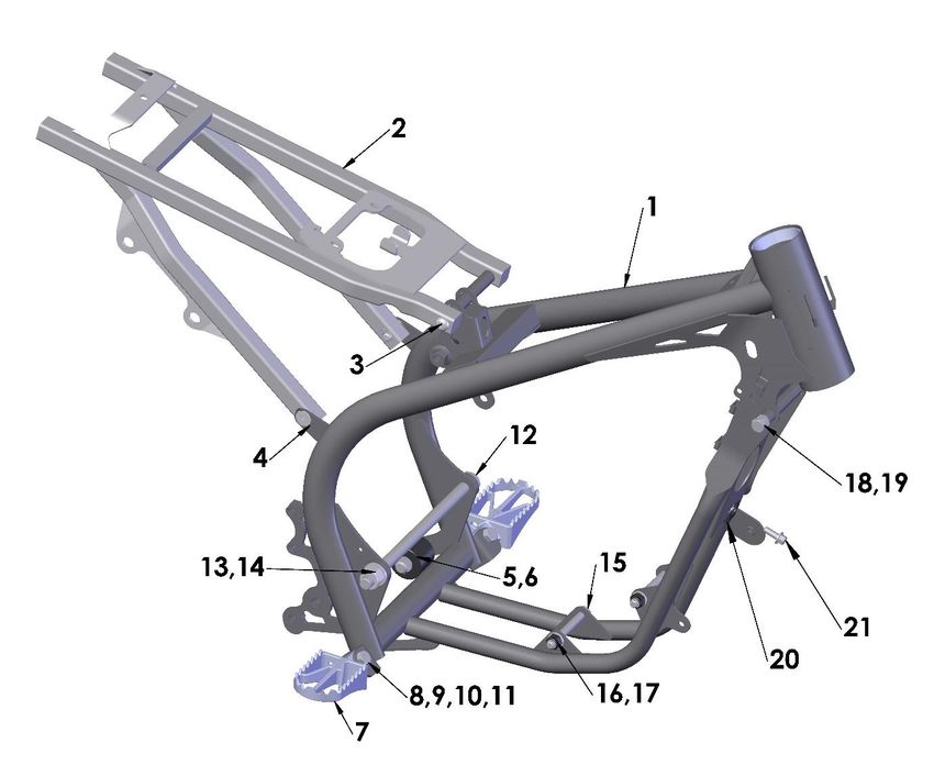
41Parts – Frame
Frame
REF # PART # DESCRIPTION
1 FAC62019G FRAME WELDED ASSEMBLY
2 FAC60016 SUBFRAME CX65
3 HCBB0835 8X35MM BUTTON HEAD SCREW (2 REQ’D) – TOP MOUNT
4 HCFH0825 8X25MM FLAT HEAD CAP SCREW – (2 REQ’D) – BOTTOM MOUNT
5 FCC60020 CHAIN ROLLER WITH BOLT, BEARINGS & SEALS
6 BCDC0153 WASHER
7 TCMU0139 FOOTPEG SET ULTRA WIDE CX65 WITH SPRINGS
8 TCC60012 SPRING – FOOTPEG - ULTRA WIDE 07 (2 REQ’D)
9 FCMU0031 CLEVIS PIN - FOOTPEG
10 HCWF0801 8mm FLAT WASHER
11 HCCP0008 COTTER PIN 1/8 X 3/4
12 GCC60020 SWINGARM PIVOT BOLT - TI
13 HCWF1202 12MM FLAT WASHER
14 HCNL1201 12MM LOCKNUT
15 HCBH0865 8X65MM HEX HEAD – FRONT ENGINE MOUNTS (2 REQ’D)
16 HCWF0801 8MM FLAT WASHER – FRONT ENGINE MOUNTS (4 REQ’D)
17 HCNL0801 8MM LOCKNUT – FRONT ENGINE MOUNTS (2 REQ’D)
18 HCBH0807 8X20MM HEX HEAD – STEERING STOP (2 REQ’D)
19 HCNS0801 8MM NUT – STEERING STOP (2 REQ’D)
20 HCHA0003 6mm CLIP NUT
21 HCBF0616 M6 x 16 FLANGE HEAD BOLT
NOT SHOWN MCMUZT28 ZIP TIE – REUSABLE
42Parts – Front Wheel
Front Wheel
REF# PART # DESCRIPTION
1 WAC6F018 WHEEL 14” FRONT WITH BEARINGS & SEALS (NO TIRE, OR TUBE), BLACK
2 WCC60122 HUB FOR CX65 – FRONT
3 WCMU1418BLK 14” RIM, BLACK
4 WKC6F018 SPOKE W ALUMINUM NIPPLE-FRONT WHEEL-65 (28 REQ’D)
5 WCDCTU14 TUBE – 60/100-14 FRONT
6 WCC6F014D32 TIRE - FRONT- 60/100-14 - DUNLOP MX3S
7 WCC60024 PLUG – AXLE - NON BRAKE SIDE (SMALER ONE)
8 WCC60021 AXLE FRONT STEEL
9 WCC60029 SEAL BEARING NON-BRAKE SIDE FRONT HUB
10 WCC60027 BEARING, WHEEL-SEALED (2 REQ’D)
11 WCC60030 SPACER WHEEL BEARING FRONT
12 WCC60026 SEAL BEARING BRAKE SIDE FRONT HUB
13 ZCMUOR22 O’RING – SPACER - FRONT AXLE
14 WCC60025 WHEEL SPACER FRONT LEFT
15 WCC60023 PLUG – AXLE - BRAKE SIDE (LARGER ONE)
16 ZCKGB017 O’RING – AXLE CAP
17 BCC60100 BRAKE ROTOR - FRONT
18 HCBF1612 M6X12mm FLANGE HEAD – LOW PROFILE (4 REQ’D)
19 WCMU0110 RIM LOCK – 1.4/1.6
20 WCDC0008 RIM LOCK SPACER
21 HCWF0801 8mm FLAT WASHER
22 HCNS0801 M8 NUT
23 WAC6F118 FRONT HUB ASSEMBLY WITH BEARINGS, SEALS, AND SPACER
TOOL MCMUTL17 WRENCH – SPOKE
43Parts – Front Brakes – Master Cylinder
Front Brakes
REF# PART # DESCRIPTION
BAC60017 ASSY – FRONT BRAKE SYSTEM COMPLETE - FRONT CX65
1 BAC60016 ASSEMBLY - BRAKE MASTER CYLINDER (M/C) W LEVER ASSY
2 BKC60008 CAP & BLADDER KIT ZL150
(CAP, BLADDER & (2) M3-0.5 X 6mm LONG PHILLIPS SCREW)
3 BCC60058 CLAMP – M/C ZL150
4 HCBF1625 M6-1.0 X 25mm LONG FLANGE HEAD BOLT
5 BCMU0060 PIVOT BOLT – PIVOT BLOCK TO MASTER CYLINDER HOUSING
(BOLT & CLIP)
6 BCC60017 BOOT – PISTON END COVER
7 BKC60015 REBUILD KIT – MASTER CYLINDER ZL150
(PISTON, SEALS, SPRING, CLIIP & RETAINING WASHER)
8 CKC60004 LEVER ASSEMBLY - CLUTCH / BRAKE - BRAKEAWAY ROLLER
(LEVER ON PIVOT BLOCK W ROLLER & ADJUSTMENT SCREW W
NUT)
9 HCBC0502 M5 X 20 SOCKET HEAD CAP SCREW - LEVER POSITION ADJUSTMENT
10 HCNL0501 5MM LOCKNUT
11 CKC60005 PIVOT BOLT KIT – LEVER TO PIVOT BLOCK
(MALE AND FEMALE BOLTS)
12 HCSS0601 SET SCREW – PRESET
13 CCC60015 LEVER ONLY – CLUTCH OR BRAKE
ACCESSORY BAMU0005 LEVER ASSEMBLY - SHORTY
NOT SHOWN BCMU0116 BOOT – PIVOT COVER
NOT SHOWN CCC60026 SPRING – LEVER RETURN
NOT SHOWN CCC60025 SPACER – SPRING CENTERING
NOT SHOWN BCC60054 LINE – FRONT CX65 ZL150
44Parts – Front Brakes – Caliper
Front Brakes
REF# PART # DESCRIPTION
1 BAC60008 ASSY COMPLETE – FRONT CX65 (M/C-LINE-CALIPER) ZL150
2 BAC60009 CALIPER ASSY – CX65 ZL150
3 BKC60003 CALIPER FASTENER KIT ZL150
PAD PIN - ZL150
CLIP - PIN ZL150
2 - M6X32mm LONG ZL150
4 BKC60002 SEAL KIT – CALIPER ZL150
1 - CALIPER CENTER SEAL ZL150
4 - SEAL BRAKE PISTON ZL150
5 BCC60068 PISTON – CALIPER ZL150 (4 REQUIRED)
6 BCC60050 PAD SET ZL150
7 BCC60051 SPRING – PAD ZL150
8 BCC60033 BLEED SCREW & CAP KIT
NOT SHOWN BCC60054 LINE FRONT CX65 ZL150
45You can also read