Installation and Operation Manual Underground Blast Resistant Bomb/Fallout Shelter - for American Safe Room's
←
→
Page content transcription
If your browser does not render page correctly, please read the page content below
Installation and Operation Manual
       for American Safe Room’s
  Underground Blast Resistant
     Bomb/Fallout Shelter

                             Revision: F.1 — May 2, 2007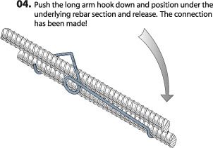
Underground Blast Resistant Fallout Shelter
                                                                                     Revision: F.1 — May 2, 2007

Table of Contents
Forward ................................................................................................................... 5
Contact information ...................................................................................................... 6
Description — general discussion ................................................................................... 7
Description — principals of a protected space .................................................................. 8
Description — components of a protected space .............................................................. 9
Description — components of a protected space, continued............................................. 10
Description — verifying that you have a true protected space .......................................... 10
Description — entry and exit ....................................................................................... 11
Description — options ................................................................................................ 12
Description — major components ................................................................................. 13
Choosing the location ................................................................................................. 14
Excavation ................................................................................................................ 15
Building the foundation — overview .............................................................................. 16
Building the foundation — form construction ................................................................. 17
Building the foundation — form dimensions ................................................................... 18
Building the foundation — laying the rebar .................................................................... 19
Building the foundation — laying the rebar, continued ..................................................... 20
Building the foundation — pouring the concrete ............................................................. 21
Constructing the walls — types of concrete blocks .......................................................... 22
Constructing the walls — the types of courses ............................................................... 23
Constructing the walls — horizontal rebar reinforcement ................................................. 24
Constructing the walls — preparation and laying a test run .............................................. 25
Constructing the walls — laying the courses .................................................................. 26
Constructing the walls — critical points ......................................................................... 27
Constructing the walls — rebar reinforcement ................................................................ 28
Trusses — locations ................................................................................................... 29
Trusses — setting and centering .................................................................................. 30
Ceiling form boards — installing the long perimeter form boards ....................................... 31
Ceiling form boards — installing the short perimeter form boards ..................................... 32
For detailed angle bracket dimensions consult the detailed Parts Drawings Manual .............. 32
Ceiling form boards — bottom form board locations ....................................................... 33
Ceiling form boards — bottom form board installation ..................................................... 34
Ceiling form boards — cutting them out of the plywood panels ........................................ 35
Ventilation system — description .................................................................................. 36
Ventilation system ducts — overview ............................................................................ 37
Ventilation system — installing the intake and outflow ducts ............................................ 38
Riser structure — overview .......................................................................................... 39
Riser structure — block lay-up overview text ................................................................. 40
Riser Structure — block lay-up overview figures ............................................................. 41
Riser Structure — block lay-up course maps .................................................................. 42
Rebar — naming conventions ....................................................................................... 43
Rebar dimensions — foundation reinforcement ............................................................... 43
Rebar dimensions — horizontal wall reinforcement .......................................................... 44
Rebar dimensions — ceiling reinforcement ..................................................................... 45
Rebar dimensions — riser reinforcement ........................................................................ 46

                                                      NOTICE
                              Copyright ©2006-2007, Leonard M. Henrikson
                          All rights reserved. No portion of this manual shall be
                      copied, transferred, or sold without express written consent.
Underground Blast Resistant Fallout Shelter
Revision: F.1 — May 2, 2007
Table of Contents — continued
Note: see page 4 for a “visual” Table of Contents that shows an isometric view of the shelter with the
major assemblies listed by section letter.
Rebar splinting — perpendicular installation ................................................................... 47
Rebar splinting — parallel installation ............................................................................. 48
Rebar installation — wall and ceiling .............................................................................. 49
Rebar installation — wall and ceiling .............................................................................. 50
Rebar installation — ceiling .......................................................................................... 51
Rebar installation — ceiling .......................................................................................... 52
Rebar installation — ceiling, continued ........................................................................... 53
Rebar installation — ceiling, continued ........................................................................... 54
Rebar installation — riser ............................................................................................ 55
Rebar installation — riser, continued ............................................................................. 56
Ingress/egress options — blast hatch ........................................................................... 57
Ingress/egress options — blast door ............................................................................ 58
Ingress/egress options — blast door, continued ............................................................. 59
Ingress/egress options — ladder installation .................................................................. 60
Ingress/egress options — ladder installation, continued .................................................. 61
For construction dimensions consult the detailed............................................................ 61
Parts Drawings Manual ................................................................................................ 61
Ceiling — pouring the concrete ..................................................................................... 62
Sealing the walls and ceiling ......................................................................................... 63
Optional equipment — electrical connection kit ............................................................... 64
Optional equipment — plumbing kit .............................................................................. 65
Optional equipment — plumbing kit, continued ............................................................... 66
Optional equipment — plumbing kit, continued ............................................................... 67
Load calculations - trusses .......................................................................................... 68
Load calculations - ceiling forms ................................................................................... 69
Load calculations - ceiling forms, continued ................................................................... 70
Load calculations - ceiling ............................................................................................ 71
NOTICE
Copyright ©2006-2007, Leonard M. Henrikson
All rights reserved. No portion of this manual shall be
copied, transferred, or sold without express written consent.Underground Blast Resistant Fallout Shelter
Revision: F.1 — May 2, 2007
Table of Contents — assemblies
The letters called out below correspond with the respective section in this manual:
L
N
L
L
O
M
J
I
K
H
H
G
K
NOTICE
Copyright ©2006 Leonard M. Henrikson
All rights reserved. No portion of this manual shall be
copied, transferred, or sold without express written consent.Underground Blast Resistant Fallout Shelter
Revision: F.1 — May 2, 2007
Forward
This manual is furnished as an information source to our customers. It is NOT to be confused with
the “free bomb shelter plans” offers that permeate the internet. This entire kit has been engineered
from “below” the ground on up to be a safe refuge in case of nearby catastrophic events such as
conventional or nuclear detonations or warfare chemical or biological releases.
The design principals used to develop this kit include economy of price and labor as well as the
“human nature” element that has been documented when civil social order breaks down.
The American Safe Room Blast Resistant Bomb/Fallout Shelter System facilitates a simple mechanism
to construct a true steel-reinforced concrete underground bunker. Every known (documented)
underground bunker that is constructed by people and governments who seem to have unlimited
resources use steel-reinforced concrete as a building system. Nobody with unlimited resources buries
a culvert and calls it a bunker.
This underground shelter designed to keep you alive during a variety of real-life emergencies. Imagine
having a nearby safe place to retreat to in case of terrorist attacks, home invasion robberies, social
unrest, or natural disasters. If the roads are clogged and you cannot evacuate, where will you seek
shelter?
You may purchase all of the individual kit systems necessary to construct the bunker or you may pick
and choose which parts to buy and which parts to make yourself.
The Detailed Parts Drawings Manual (a separate document from this one) has all of the
manufacturing drawings for the components of the entire structural system and is available from us
for a reasonable, refundable price. Please understand that all of these parts require multiple
operations in order to make the complete part and that all of these parts must mate with (exactly fit)
with the other parts to create a shelter that will withstand a nearby detonation.
The Detailed Parts Drawings Manual includes:
• Steel trusses (cut to length and holes made for the rebar)
• Steel riser trusses (special trusses to support the riser)
• Riser bearing plates (smaller trusses that support the riser)
• Truss end brackets (the parts that ensure the trusses are positioned)
• Rebar lengths and formed shapes (exact dimensions for all the rebar)
• Ladder assembly and brackets (complete manufacturing drawings)
• Steel ventilation intake and exhaust piping and connections
The material in this manual is copyrighted and may not be reproduced either in drawing format or in
actual parts without the expressed permission of American Safe Room.Underground Blast Resistant Fallout Shelter
Revision: F.1 — May 2, 2007
Contact information
American Safe Room, Inc.
PO Box 255
868 Murdock Drive
Oakland, OR 97462
Telephone: 541-459-1806
FAX: 503-212-6695
E-mail: info@mailasr.com
Websites: www.AmericanBombShelter.com
www.AmericanSafeRoom.com
www.AmericanIsolationRoom.com
American Safe Room is owned, operated, and located in
the United States of America.
Section
A
Page 6Underground Blast Resistant Fallout Shelter
Revision: F.1 — May 2, 2007
Description — general discussion
The purpose of the American Safe Room Underground Blast Resistant Fallout Shelter is to provide
an underground protected space that is safe, economical, and discrete to construct. A properly
constructed, tested, and supplied underground shelter can sustain the occupants through a variety
of potential hazards. These include conventional and nuclear detonations, warfare gas events,
biological toxin releases, industrial accidents, natural disasters, and other serious social occasions
that may cause people around you to behave irrationally.
Previously, the cost of a true underground steel-reinforced concrete shelter has been so
prohibitive that only wealthy individuals, corporations, and governments have been able to afford
them. Almost all of the underground blast-resistant shelters that have been documented have been
built out of steel-reinforced concrete.
It is for this reason that American Safe Room has designed an affordable underground shelter that
can be purchased and installed without the intrusiveness of neighbors knowing that you are
prepared for the worst. Prefabricated underground shelters cannot be explained as a wine cellar,
basement, or other common underground locations. This comprehensive kit can be installed in the
most discrete manner that gives you plausible deniablility that you are now equipped with a true
underground bomb shelter.
This user-friendly kit ships motor freight (on pallets by a trucking line) with all of the major
components necessary to construct the most cost efficient below ground shelter possible. We can
do this because we put our resources into the design and development instead of economy of
construction. By purchasing the bulky, heavy, and easily obtainable items locally, you save on
shipping costs, you can shop around for the best prices, and you have the option to defray the
cost of the entire structure and installation over several different purchases from several different
vendors over the course of the installation.
The American Safe Room Underground Blast Resistant Fallout Shelter can be purchased as a
complete system or you may choose from the different components to upgrade an existing fallout
shelter or underground location.
The width of the shelter is fixed at 10 feet wide, but the length of 21-feet, 4-inches may be
modified longer or shorter in increments of 32-inches.
CAUTION Be sure to procure your permits first, before ordering your shelter kit.
CAUTION Do not substitute any of the materials listed in this manual.
CAUTION Read and understand every page of this manual and the related manuals before
beginning this project. This manual is presented in the order of construction, but
there are many sections that require you to understand what is going to happen
in a subsequent section before completing the previous section. No section can
be assumed to be in isolation of the other sections.
Section
B
Page 7Underground Blast Resistant Fallout Shelter
Revision: F.1 — May 2, 2007
Description — principals of a protected space
While this shelter is designed to protect the occupants from the kinetic effects (projectiles and
debris) of a nearby detonation, a discussion of the nature of air filtration and ventilation in sealed
shelters is pertinent to the understanding of this critical aspect of protection.
The inside of a shelter is described as a “protected space.” This term is used to describe any
enclosure that denies airborne toxins from entering into that space. In order to protect the
occupants, you must control the flow of air through this space. The most efficient means of doing
this is with positive pressure (overpressure — or “pressurized” air). In other words, the air inside
the protected space is at a slightly higher pressure than normal atmosphere, preventing the
migration of toxins into the protected space even if it is not sealed completely. If there is a crack or
a small hole in the protected space, the positive pressured and filtered (safe and breathable) air
inside will flow outward, instead of toxin laden air flowing inwards. Both static and mobile military
protected spaces (command/control centers and vehicles such as tanks) all rely upon this principal.
The air that is introduced into your protected space needs to be safe, breathable air that is filtered
from nuclear, biological, and chemical toxins. This air must be pressurized as it is introduced
into the shelter until a preset positive pressure (overpressure) is achieved inside the shelter. This is
a function of the fan (blower) inside the Safe Cell and the overpressure relief valve working together
to control the pressure inside the shelter.
How well the protected space is sealed, and how the air is drawn in, filtered, pressurized, and then
expelled must be engineered as a complete system. Air acts as a fluid — taking the path of least
resistance in the constant attempt to equalize it’s pressure. This pressure forces the air into your
shelter — bringing with it whatever toxins it contains.
The significance of treating your protected space as a complete system and not just a
collection of separate components thrown together cannot be overstated.
Air inlet Air outlet
Figure B-1
Blast Hand Blast valve
valve pump
Overpressure
relief valve
Wall
bracket
Inlet Section
hose Safe Cell
NBC filtration/ventilation system
B
Page 8Underground Blast Resistant Fallout Shelter
Revision: F.1 — May 2, 2007
Description — components of a protected space
All of the components that American Safe Room designs are built to work together in order to
achieve and maintain a true protected space. Please see Figures B-1 and B-2 that shows all of these
components in their proper place.
Inlet and outlet ventilation pipes
These are heavy duty steel pipes designed to be either poured in place or added to an existing
underground shelter. They have a 180 degree bend at the top in order to keep rain, debris, and
fallout from entering the pipes.
Automatic double-acting blast valves
These are designed to let low pressure air pass through them in order to allow the Safe Cell to draw
air in and the overpressure relief valve to let air out. Their internal valves are in a central, neutral
position and can slam shut either way — double acting. In the event of a nearby detonation, the
initial wave of extremely high (which can be well beyond hurricane strength) air pressure will
automatically close the valve — keeping this deadly air pressure and the toxins that it contains
from entering your protected space. Then, as the air is blown outward from the center of the
detonation, a secondary wave of vacuum (negative air pressure) will follow. The blast valves will
automatically close again — ensuring that your protected space does not become a vacuum
chamber — a vessel with negative (less than ambient) air pressure. If this happens, as the outside
pressure returns to normal, the air (and whatever it contains) will be sucked into your shelter. These
two conditions of extremely high pressure and vacuum, happen very rapidly — in a matter of
seconds. As the air pressure returns to normal, the internal valves return to their central, neutral
position allowing the relatively low pressures of filtered air from the Safe Cell to pass through them
— achieving true ventilation. Blast valves must be used in pairs — protecting one ventilation pipe,
but not the other is not protection. Pressurized air and vacuum does not care which port it enters
and either condition caused by a nearby detonation could be lethal. These blast valves are heavy
steel units designed with the Israeli standard hole pattern on the mounting flange.
Consult the ASR-48/100N Manual for more information
Blast resistent steel inlet Blast resistent steel outlet
ventilation pipe ventilation pipe
Pipe form
Pipe form
for reinforcement concrete
for reinforcement concrete
Blast valve
Hand Bellows
Blast valve
Overpressure valve
12 VDC
battery
Section
110/220 VAC power cord
Connection hose Safe Cell ventilation/filtration system
B
Page 9
Figure B-2Underground Blast Resistant Fallout Shelter
Revision: F.1 — May 2, 2007
Description — components of a protected space, continued
The filtration/ventilation system — the Safe Cell
This component consists of an internal blower (fan) and three different types of filters: a pre-filter
assembly (gross and fine), a nuclear-grade (individually DOP tested) HEPA filter, and a warfare gas
grade carbon adsorber. It also has an internal automatic switching power supply that will trickle-
charge a user-supplied 12 VDC battery while running on 110-220 VAC. In the event of a power
outage, this power supply will automatically revert to the battery and keep the blower running —
maintaining an overpressure. When the AC power is restored, it will automatically revert back to the
AC power and recharge the battery. A normal (automotive type) battery will keep the Safe Cell
operating from 16 to 24 hours and a deep cycle (marine type) battery will last longer — enough to
give you the peace of mind to go to sleep knowing that overpressure will be maintained in your
protected space in the event of a power failure.
The secondary backup system — the optional emergency manual air pump
In the event of a long term power outage, even a huge bank of batteries will not suffice to power a
blower that is powerful enough to maintain positive pressure in your protected space for very long.
The manual air pump installs onto the top of the Safe Cell in about 5 seconds and you can then begin
pumping — drawing air into your shelter and displacing (removing) the carbon dioxide that is
exhaled by the occupants. A person cannot maintain an overpressure by manual power — no
matter what type of motion is used, but the real danger in a sealed space is carbon dioxide
buildup. We know from submarine, mine, and avalanche disasters that humans will succumb to
carbon dioxide poisoning long before oxygen depravation when constrained in an enclosed, airtight
space.
The overpressure relief valve
This valve meters out the positive pressure air in the same way that a relief valve on a pressure
cooker works. It is calibrated to only release air at a certain pressure so that positive pressure is first
created and then maintained in your protected space. Since this is the air outflow port of the
protected space, it should be on the opposite side of the shelter in order to ensure that the safe,
breathable air introduced by the Safe Cell is circulated throughout the shelter.
Description — verifying that you have a true protected space
Test kit
The optional test kit provides a means to verify that all of the components of your protected space
are working properly. It consists of a differential manometer — which is an instrument that takes two
different readings of air pressure. One reading is for the your protected space and another reading is
for an adjacent space (outside). It displays the difference of pressures on a scale — like a
thermometer. This instrument is used by temporarily routing a flexible tube through a small opening
to the adjacent space, turning on your Safe Cell, waiting a short time until the overpressure is
created, and then reading the display of the difference in pressures between your shelter and the
adjacent space. Another component of this kit are smoke punks — smoke generating devices. They
are used by holding them near any likely places inside your protected space that would leak — such
as around the hatch or door, the blast valve mounting flanges, or electrical conduit or plumbing
fittings. If the smoke either rises straight up or is blown outward due to positive air pressure in your
protected space, you have proven that air is not being drawn inward. If the smoke is blown inward,
you have proven that there is not enough positive pressure inside your protected space and the area
where you tested is not sealed properly.
Differential pressure monitor
For ongoing, real-time data regarding the difference in air pressure between your Section
protected space and the adjacent space (outside), we offer an optional differential
pressure gauge. This device works similar to the differential manometer in the test
kit described above, but it has a dial gauge and is permanently mounted in the
B
Page 10
hatch or door of your shelter.Underground Blast Resistant Fallout Shelter
Revision: F.1 — May 2, 2007
Description — entry and exit
There are some options to consider when deciding where and how to position and construct the
ingress/egress (enter/exit) points of the shelter.
Since this is designed to be an underground shelter, most options will include what we call a “riser.”
That is a shaft designed to convey occupants to and from the shelter up to the surface. It is
constructed from concrete blocks, steel reinforcements, and a poured concrete filler. In this shaft,
you can have a top opening blast hatch, a side opening blast door, or both. The risers can be built
to any “block” height increment — around 8-inches (8, 16, 24, etc.). You may opt to have more than
one riser for redundancy, but remember, all risers must be built over special roof trusses that we call
“riser trusses.” These are made to withstand the added weight of the riser and the direct pressure on
the riser from the wave of high pressure air that radiates from a nearby detonation. See Section L —
riser construction for more information.
Both the hatches and doors are manufactured by American Safe Room and engineered to withstand
a 50 PSI (pounds per square inch) blast. They feature a lockout mechanism that prohibits
unauthorized entry into your shelter when you are not inside and the handle (opening mechanism)
can be easily removed and taken into the shelter with you to deter people from trying to defeat the
door and enter your shelter while you are inside. They are designed to have the least
advantageous purchase points possible for leverage devices (crowbars) and pulling devices (tow
ropes and winches). In other words, if someone were to maliciously desire access to your shelter
while you were inside of it, they would find it difficult to locate places on the hatches or doors to gain
a purchase to force them open. See Section N — ingress/egress options for more information on
the hatch and door options.
Both types of doors are fabricated from steel and are purposely constructed as hollow forms. They
are pre-hung on a frame with mounting flanges. The heavy-duty mounting fasteners are included.
Once the hatch or door is mounted in place, concrete is poured into the cavity of the door by the
installer. This internal concrete does several very important things: it makes it nearly impossible for an
acetylene cutting torch to burn it’s way through the door, it adds mass that will help to block
radiation, it structurally supports the steel skin of the door to add strength, and it makes the door
relatively light when mounting on the riser — because the concrete is poured after the door is
mounted.
Another aspect to consider is how to get the occupants down into the shelter. You can use our
ladder system, construct a stair system, or in the near future, we will offer our own integrated stair
system as an option. Also coming soon is a powered lift (electrical dumbwaiter) that will use our
existing ladder as the rails to allow you to raise and lower heavy items (not designed or rated for
people) into and out of your shelter. There are many heavy items — such as water (8 pounds per
gallon), buckets of grain, or pets that are difficult to convey (up or down) a ladder. See Section N —
ingress/egress options for more information on the ladder.
Also, as an option, the door may be mounted in the side wall of the shelter. This can be useful if the
access to your shelter is through a basement or other existing underground locations. But you must
allow for the door opening when building the shelter walls.
Section
B
Page 11Underground Blast Resistant Fallout Shelter
Revision: F.1 — May 2, 2007
Description — options
There are many options that you may have with your underground blast resistant shelter. Here are
a few of them:
The length may be changed (decreased or increased) in 32-inch increments. This dimension is
determined by the block spacing. Please contact American Safe Room to find out more information
about length options. See Section A for our contact information.
The risers structure may be any block height increment — about 8 inches. And you may have
more than one riser for redundancy of an ingress and egress point. The riser can have a top
mounted, horizontally oriented hatch or a side mounted, vertically oriented door, or both. Please
note that the risers must be located on top of the riser trusses — these are constructed of heavier,
stronger wide flange beams in order to take the added mass of the riser — and, more importantly
the pressure pushing down from a blast wave directly on top of the riser. See Section L for
information on how the riser is construction and see Section N for information on hatch, door,
and ladder options.
You may opt for either an ASR-48-NBC Safe Cell or an ASR-100N-NBC Safe Cell. The ASR-48-NBC
puts out 48 cubic meters of safe, breathable air per hour and the ASR-100N-NBC puts out 100
cubic meters of safe, breathable air per hour. The anticipated number of occupants is the major
consideration point, but shelter size is also an issue.
You may opt to handle human waste (sewage) internally with a chemical toilet and not plumb your
shelter into your existing septic system. See Section R for the optional plumbing connection kit.
You may opt to have only internal battery power inside your shelter or run electrical wires through
conduit into your shelter. We strongly advise against any type of generator inside the shelter.
Carbon monoxide is not something that can be removed by filtration. You can route the exhaust
out of the shelter, but even the smallest leak of this exhaust can become dangerous. Remember,
you will be in an enclosed space, underground, and possibly without the benefit of relying upon an
organized rescue effort if you succumb to carbon monoxide (or carbon dioxide) poisoning. See
Section Q for the optional electrical connection kit.
Our product line has been installed on heavy equipment moving radioactive earth at a former nuclear
plant, in bomb shelters, military vehicles, first responder hazardous waste clean up tents, safe
rooms, and in our own homes. We can guide you through the selection process. Please see the
contact information in Section A.
Section
B
Page 12Underground Blast Resistant Fallout Shelter
Revision: F.1 — May 2, 2007
Description — major components
This description legend is for Figure B-1 and B-2
A ...... Blast resistant hatch and ladder
B ...... Concrete filled blast door
C ...... Reinforced 10-inch concrete ceiling
D ...... 10-inch I-beam roof trusses
E ...... Steel reinforced concrete filled
8-inch block wall.
F ....... Blast resistant heavy steel A
ventilation ducts:
intake and exhaust
G ...... Blast valves on intake and exhaust
H ...... Full NBC positive pressure
filtration
unit with hand and battery backup
B
C
D
F
E
G
H
Section
Figure B-1
B
Page 13Underground Blast Resistant Fallout Shelter
Revision: F.1 — May 2, 2007
Choosing the location
Careful forethought and planning must be given before an underground structure is started.
1. ..... The structure or its foundation may not be lower than the high water table.
2. ..... The location should have sufficient slope to allow for surface water drainage.
3. ..... The allowable compaction ratio of the soil at the footing should not be less than a 10,000
pounds per square foot — otherwise a thicker footing may be required.
4. ..... Procure all required local building permits.
5. ..... With fully or partially buried shelters make sure that you have sufficient space and access for
needed construction equipment for excavating and lowering the pallets of loaded block into the
finished excavation.
Do not attempt to construct your under ground shelter below the high water table,
CAUTION Be sure to consult with a local soil expert or drill appropriate test holes beforehand.
Section
E
Page 14Underground Blast Resistant Fallout Shelter
Revision: F.1 — May 2, 2007
Excavation
For shelters and bunkers that are to be constructed underground it will be necessary to excavate an
opening with at least 24 inches of clearance on each side of the wall in order to have the room to
construct the shelter walls.
The appropriate slope of the walls of the excavated holes must be maintained in order to prevent
sliding of the soil to the bottom of the hole. This angle of this slope is dependant upon the soil type.
The depth of the excavation must include the following variables:
1 ...... thickness of the foundation
2 ...... height of the wall
3 ...... thickness of the ceiling
4 ...... thickness of the over cover
The excavation dimensions shown in figure F-1 below are typical for the standard underground
shelter described in this manual with an overhead backfill (earth covering) of 20-inches above the
typical ceiling depth of 10-inches.
Figure F-1
Section
F
Page 15Underground Blast Resistant Fallout Shelter
Revision: F.1 — May 2, 2007
Building the foundation — overview
The foundation is constructed at the bottom of the excavation from steel reinforced concrete.
The foundation drawings shown in figures G-1 through G-6 are typical for all the optional equipment
shown in this manual.
The foundation concrete thickness of 7.1/2-inch is based on a minimum concrete strength of 4,000
pounds per square inch (PSI) placed on an undisturbed or re-compacted soil having a minimum
allowable load of 10,000 per square foot.
If either of these conditions can not be met a thicker foundation slab may be required, consult your
local building department for direction.
Failure to read, understand, and follow the simple “foundational” requirements
CAUTION above may result in a catastrophic failure of your underground shelter. It may sink
farther into the ground, buckle, and/or cave in. Use the appropriate concrete,
pour it as shown in this manual, and know the dirt you are laying it on.
Figure G-1
Section
G
Page 16Underground Blast Resistant Fallout Shelter
Revision: F.1 — May 2, 2007
Building the foundation — form construction
Materials needed:
G-1 ... 2 x 8 inch boards for the side forms
G-2 ... 2 x 4 x 16 inch long support stakes
G-3 ... 2 x 2 x 12 inch long backup stakes
G-4 ... brace boards
G-2
G-2
G-1
G-3
G-4 G-4
G-3 G-1
Figure G-2 G-2
Stakes every 18-inches with back-ups every 4-feet
Section
G
Page 17Underground Blast Resistant Fallout Shelter
Revision: F.1 — May 2, 2007
Building the foundation — form dimensions
The inside dimensions of the form will be 22-feet long by 10-feet, 8-inches wide by 7.1/2-inches
high.
Start by laying out a plumb line, and insure the square by taking a diagonal measure at all four
corners on the long axis. All four corners should read the same: 24-feet, 5.3/8-inches.
Using the same procedure recheck the actual wooden form for being square after it’s construction —
but before the concrete pour.
Figure G-3
Section
G
Page 18Underground Blast Resistant Fallout Shelter
Revision: F.1 — May 2, 2007
Building the foundation — laying the rebar
Place 1/2-inch (number-4) rebar, as per figure F-4 through figure F-6
RB-1 .......... 10 pieces latitudinal run, 120-inches in length
RB-2 .......... 12 pieces longitudinal run, 120-inches in length
RB-3 .......... 30 pieces corner bend, 11.3/4-inches x 21-inches
Figure G-4
RB-3
RB-2 RB-1
RB-3
Figure G-5 Section
G
Page 19Underground Blast Resistant Fallout Shelter
Revision: F.1 — May 2, 2007
Building the foundation — laying the rebar, continued
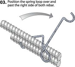
Tie all rebar intersection connections as shown in the rebar tying part of Section M of this manual.
RB-3 RB-1 RB-2
Figure G-6
Section
G
Page 20Underground Blast Resistant Fallout Shelter
Revision: F.1 — May 2, 2007
Building the foundation — pouring the concrete
This section discusses concerns of both of the concrete pours.
Concrete ordering specification
Minimum 4,000 psi strength, 3/4-inch minus aggregate, and a 5-inch to 6-inch slump.
Pouring sequence
The concrete floor is poured finished and allowed several days curing time before commencement of
the wall and ceiling construction. Then the walls and the are constructed, the ceiling trusses laid, the
ceiling forms constructed, the riser assembly is constructed, and the second concrete pour is done.
Before ordering concrete
Make sure that the worksite is clean and free of obstacles and that sufficient space and workroom
exists before ordering in equipment. Truck turnaround area may be a issue with some sites.
Round up when ordering concrete to ensure that you have enough to complete the fill.
Ensure that the concrete supplier is aware of the pour elevations of the shelter — the trucks that
pour the concrete need to have the capability of accurately pouring concrete below ground level. The
minimum depth that the concrete will be poured is 10 feet, 6 inches.
Minimum concrete quantities
Note quantities below are the minimum for the standard shelter design as described in this manual, if
you have modified the shelter design be sure to modify your concrete requirement accordingly.
The standard block wall cavities and ceiling are poured as a single unit.
Each 10-foot section of 8-foot high wall will require 0.95 cubic yards of concrete.
The total wall including the standard riser is approximately 70 linear feet, requiring 6.65 cubic yards of
concrete.
The ceiling of 10-foot x 21.5-foot x .875-foot (10.1/2-inches) requires 6.9 cubic yards of concrete.
Total minimum concrete requirement is 13.6 cubic yards of 4,000 PSI high strength concrete.
Floor: 5.5 cubic yards.
Walls and Ceiling: 13.6 cubic yards.
Total concrete: 19.1 cubic yards
See Section O — pouring the ceiling and walls before proceeding with this step. The two concrete
pours become integral and both Section G and O should be read and read and understood before
proceeding.
Section
G
Page 21Underground Blast Resistant Fallout Shelter
Revision: F.1 — May 2, 2007
Constructing the walls — types of concrete blocks
There are 7 types of concrete blocks used in the wall and riser assembly. The bond bridge blocks
have a channel cast into the top of them that allows a section of rebar to be bonded horizontally into
the wall.
For complete dimensions of these parts,
consult the Detailed Parts Drawings Manual available at: www.AmericanBombShelter.com
Figure H-1
Standard Figure H-4
concrete block Half bond
bridge block
Figure H-2
Figure H-5
Straight bond
Half end cap
bridge block
bond bridge
block
Figure H-3
Left hand Figure H-6
corner bond Right hand
bridge block corner bond
bridge block
Figure H-8 Figure H-7
Standard half End cap bond
block bridge block
Section
Standard concrete block 8-in x 8-in x 16-in.
H
Page 22Underground Blast Resistant Fallout Shelter
Revision: F.1 — May 2, 2007
Constructing the walls — the types of courses
A “course” is an industry term referring to a single layer of concrete blocks.
The wall assembly will consist of 11 courses of 45 blocks each for a total of 495 blocks.
Courses 1, 4, 7, and 10 are lateral bond courses using 8-inch x 8-inch x 16-inch bond bridge blocks
and 1/2-inch (number-4) rebar — see figures H-2, H-3, H-4, H-5, H-6, H-7, and H-10. This gives a
horizontal steel reinforcement on every third course.
Courses 2, 3, 5, 6, 8, 9, and 11 are standard 8-inch x 8-inch x 16-inch block — see figure H-1.
11
10
8 and 9
7
5 and 6
4
2 and 3
1
Figure H-9
Section
H
Page 23Underground Blast Resistant Fallout Shelter
Revision: F.1 — May 2, 2007
Constructing the walls — horizontal rebar reinforcement
This page is an overview of a typical course that have the horizontal rebar reinforcement laid into a
the bond bridge blocks.
The total 1/2-inch (number 4) rebar requirements for all four lateral bridge bond courses are:
RB-4 .......... corner bridge — 16 pieces, each 9.3/4 inches x 9.3/4 inches
RB-5 .......... end bridge — 8 pieces, 112 inches
RB-6 .......... side bridge — 16 pieces, 120 inches
H-3
RB-5
RB-4
RB-6 H-3
H-6
H-2
Figure H-10
H-6
H-3
H-2
Section
Figure H-11
H
Page 24Underground Blast Resistant Fallout Shelter
Revision: F.1 — May 2, 2007
Constructing the walls — preparation and laying a test run
Before starting to lay the blocks, drive stakes into the ground and build a form at each corner. These
stakes and forms can be made from scrap pieces of wood used on the job — see figure G-9 below.
Locate the exact corner by stretching lines from one corner form to the other as illustrated. The exact
corner will be the point at which the two lines cross.
Drop a plumb bob or laser down from each line, both at the corner point where the lines cross and at
positions about 2-feet out in each direction.
Determine the exact number of blocks required for the first course by laying out a course of block on
the dry concrete — see figure H-10. Do not use mortar for this test run — you are merely
determining the number of blocks required for the job.
Be sure to use the corner blocks where needed, and cut blocks as required.
Use pieces of 3/8-inch plywood as a spacer to fill in the mortar joint between each block. This is the
thickness of the mortar when applied.
Total mortar required for a 3/8-thick mortar bond is 37.1/2-cubic feet. Refer to the directions on the
mortar packaging to determine the number of bags of mortar needed and the set time for the mortar.
After this test run, remove the blocks and prepare for the actual laying of the first course.
Figure H-12 Figure H-13
Section
H
Page 25Underground Blast Resistant Fallout Shelter
Revision: F.1 — May 2, 2007
Constructing the walls — laying the courses
Drop plumb bobs down from the corner string and at positions
about 3' out from the corner. Mark the location of the corner
block on the footing base.
Spread the mortar out about 1" deep and 8" wide in the marked
area (see image). Extend this mortar out for a distance of about
three or four blocks in one direction.
Put a furrow in the center of the mortar with a trowel. This
furrow will force the mortar to the edge of the block when it is
laid (see image).
Set the corner block first. Be sure you are using the correct Figure H-14
block (finished end). Check the starting corner block, both
horizontally and vertically, and take time to get it positioned
correctly. All other blocks will align with this starter block, so it’s
very important to set it exactly. Follow this same procedure as
you reach the other corners, laying the first course out about
two or three blocks in each direction. Tie a line between two
bricks and stretch it between the two corner blocks on the first
course
Figure H-15
Section
H
Page 26Underground Blast Resistant Fallout Shelter
Revision: F.1 — May 2, 2007
Constructing the walls — critical points
Continue to lay the base mortar on the footing as the course
continues. Apply mortar to the ends of the blocks with a trowel
and place the block in position (see image above).
Keep all mortar joints at about 3/8". If necessary to make
spacing adjustments, fill some mortar joints 1/2" to 3/4".
If you must cut a block to fill a course, use a masonry chisel as
illustrated here. Draw a line on both sides of the block where
the cut is to be made. Strike the chisel with a bricklayer’s
hammer. You will soon learn to make such cuts easily.
Figure H-16
After you’ve laid four or five blocks, use a long mason’s level or
some type of straightedge to check the alignment of the blocks
(see image). Check both the tops of the blocks and the outside
edge for correct alignment. Tap the blocks into position to make
any alignment corrections while the mortar is still wet. Never
attempt to move a block after the concrete begins to set. Build
up the corners first. Always keep the corners about a block or
two higher than other runs until you finish the job. Keep the
guidelines between the corners at all times. They will help you
keep the blocks level at all points in each course. Be careful not
to knock the lines out of alignment.
Always keep the guidelines tight. If one side gets bumped out of
position, take a minute to level it. Use a trowel to cut away any
surplus mortar. Throw the surplus mortar back onto the
mortarboard. Keep turning the mortar with your trowel
throughout the project so small portions will not harden.
Figure H-17
Section
H
Page 27Underground Blast Resistant Fallout Shelter
Revision: F.1 — May 2, 2007
Constructing the walls — rebar reinforcement
Use a piece of 3/4" plywood or the bed of a wheelbarrow as a
mortarboard. Always wet the board or the wheelbarrow bed
before placing the mortar in it. Never mix more mortar than you
can use in about an hour and a half or two hours. On a hot day,
keep the mortar covered with a piece of plastic to hold in
moisture. Use as much water as the mortar will take and still
remain elastic. Continue to stagger the blocks-working from the
corners-and build the wall to the desired height. Take time to
level each course. Use a level that is at least 4-feet long. Lay all
blocks with the thicker end of the face shell up. Keep a leveling
string at the top of each course on each run of block. Measure
both the length and the height of the wall after every two or
three runs. Also, hold your level diagonally along the block
corners to check for accuracy (see image). If the blocks are
being laid accurately, the corners will strike evenly along a level
held in this position. Figure H-18
After all the blocks are laid and while the mortar can still be
pressed with the fingers, take a jointer and finish the mortar
joints to the appearance desired. Keep the jointer wet during
this part of the job.
You may need to add reinforcing rods to walls built extremely
high or in areas where ground pressures may vary.
Lay 1/4-inch reinforcing rods as illustrated, with the ends
overlapped 2-inches to 3-inches. Mortar can be placed directly
over the rods.
Figure H-19
Figure H-20
Section
H
Page 28Underground Blast Resistant Fallout Shelter
Revision: F.1 — May 2, 2007
Trusses — locations
I-2
I-1
I-3
Figure I-1
Place center and assemble the riser truss pair (I-1) and the riser bearing plates (I-2) as per figure
I-1, use the provided bolts located in the mounting holes of the riser trusses.
Place the remaining five standard trusses (I-3) as shown in figure I-1.
All trusses are centered on there longitudinal axis as shown
For complete dimensions of these parts,
consult the Detailed Parts Drawings Manual available at: www.AmericanBombShelter.com
Section
I
Page 29Underground Blast Resistant Fallout Shelter
Revision: F.1 — May 2, 2007
Trusses — setting and centering
truss
wall
Figure I-2
Side (elevation) view — all trusses are located on 32” centers
column truss
Figure I-3
Top (plan) view — all truss centers fall between the vertical columns in the block
form board
board bracket
Figure I-4 wall
truss/wall centering bracket
End view — all trusses are centered on their long axis as shown above
For complete dimensions of these parts,
consult the Detailed Parts Drawings Manual available at: www.AmericanBombShelter.com
Section
I
Page 30Underground Blast Resistant Fallout Shelter
Revision: F.1 — May 2, 2007
Ceiling form boards — installing the long perimeter form boards
There are three types of form boards used to form up the ceiling: the perimeter walls (long boards),
perimeter ends (short boards), and the ceiling form boards (plywood.
The perimeter wall form boards serve two functions, first to secure the trusses from movement along
the long axis of the shelter and secondly to provide the perimeter form for the poured concrete
ceiling.
You will need the following for the perimeter forms of the ceiling:
2 each 2-inch x 12-inch x 12-foot long boards
2 each 2-inch x 12-inch x 10-foot long boards
It is critical that the distance between the truss centers on both ends of the
CAUTION trusses is correct as per figures I-4 and J-3.
Using the fasteners provided with your truss kit:
1. ..... Install all board brackets to the ends of the centered trusses as shown in fig. I-4, and J-3 but
do not yet tighten the board bracket securely to the truss.
2. ..... Set the long form boards on top of the wall and against the face of the board brackets as
shown in figure J-3.
3. ..... Using the board brackets as a template, mark and drill the 3/8-inch holes for the perimeter
long form board bolts, and fasten the long form boards to the brackets.
4. ..... Adjust the long perimeter form boards so that the outside face of the board is flush with the
outside face of the wall, and tighten the board bracket truss bolts, as per figure J-3.
Form board
Section
Figure J-1
J
Page 31Underground Blast Resistant Fallout Shelter
Revision: F.1 — May 2, 2007
Ceiling form boards — installing the short perimeter form boards
1. ..... Install the two short form boards over the end walls with the outside face of the board flush
with the outside face of the wall just as the long form boards.
2. ..... Use the corner board brackets as a drill template and fasten the corners with the provided
bolts.
For detailed angle bracket dimensions consult the detailed
Parts Drawings Manual
angle bracket nut
washer
corner board bracket
washer
angle bracket bolt
short form board
long form boards
connection plate
Figure J-2
long form boards
truss
board bracket/truss bolts
perimeter form
board bolts
truss/wall centering brackets
Figure J-3
Section
J
Page 32Underground Blast Resistant Fallout Shelter
Revision: F.1 — May 2, 2007
Ceiling form boards — bottom form board locations
Ceiling form boards
Figure J-4
Ceiling form board location chart
See figure J-6 and J-7 for Figure J-5
installation and cutting guide
Section
For complete dimensions of these parts,
consult the Detailed Parts Drawings Manual available at:
www.AmericanBombShelter.com J
Page 33Underground Blast Resistant Fallout Shelter
Revision: F.1 — May 2, 2007
Ceiling form boards — bottom form board installation
The bottom form boards are constructed from 1.125 (one and an eighth inches) CDX plywood.
It individually cut into 25 pieces of exact size to nest between the truss beams while at the same time
being captured by the bottom flange of the beams.
The finished cut pieces are rotated into place from the top side of the trusses — see below.
See fig. J-5 for location map and fig. J-7 for material and cutting schedule.
You will need 6-sheets of 4-feet x 8-feet x 1-inch CDX plywood.
The true truss center dimensions may vary. Measure all cutting dimensions against
CAUTION the actual truss center dimensions before cutting — be sure to measure both
ends of the truss as the trusses may not be exactly parallel.
For ease in assembly and a secure fit the cut material should always be
2.5/8-inches to 2.11/16-inches wider than the inside flange distance.
Ceiling form board
Truss
Truss
Rotating installation technique
Figure J-6
Section
J
Page 34Underground Blast Resistant Fallout Shelter
Revision: F.1 — May 2, 2007
Ceiling form boards — cutting them out of the plywood panels
Cutting schedule for the bottom plywood form sections. All panels are 1.125-inch CDX plywood.
Because these panels will hold the uncured (wet) concrete until it cures (hardens)
CAUTION it is strongly recommended that no substitutions be made for the specified
material — if these panels fail, you will literally have tons of wet, curing (soon to be
hard) concrete sitting on the floor of your shelter.
3 sheets required
1 sheet required
1 sheet required
1 sheet required
Figure J-7
Section
For complete dimensions of these parts,
consult the Detailed Parts Drawings Manual available at:
www.AmericanBombShelter.com J
Page 35Underground Blast Resistant Fallout Shelter
Revision: F.1 — May 2, 2007
Ventilation system — description
The shelter ventilation system is in an easy to install kit form and addresses all four of the critical
requirements below.
1. ..... Sufficient air supply for the number of sheltered occupants
2. ..... A proper filtration system to insure scrubbing of nuclear, biological, and chemical contaminates.
3. ..... Explosion resistant blast valves over the intake and exhaust ventilation ducts to protect both
the filtration equipment and the occupants from high pressure blast waves.
4. ..... A regulating overpressure valve over the exhaust blast valve to insure a positive air pressure
inside the shelter is maintained, as well as a regulated outflow to insure true air throughput.
The ventilation pipes are poured in place. They must be positioned before the
CAUTION concrete pour of the ceiling.
The ASR-100N-NBC and ASR-48-NBC Safe Cell filtration units not only provide excellent protection
from an NBC event, but can also be purchased with an optional manual hand pump and an automatic
battery backup system in case of electrical line failure. See the appropriate manual for the installation
and operation of these filters.
Section
K
Page 36Underground Blast Resistant Fallout Shelter
Revision: F.1 — May 2, 2007
Ventilation system ducts — overview
Exhaust
Intake
Figure K-1
Ventilation-pipe
16-inch diameter
form tube (culvert)
Ceiling Mounting bolt
form Board
Flanged hex nut
Blast valve
Figure K-2
Mounting bolt Figure K-3
Overpressure relief valve
pattern and Detail of duct
dimensions system
Section
K
Page 37Underground Blast Resistant Fallout Shelter
Revision: F.1 — May 2, 2007
Ventilation system — installing the intake and outflow ducts
Note figure K-4 and K-5 below are for reference only and show the ventilation duct and blast valve
assembly as they will appear after the concrete has been poured.
Install the ventilation ducts through the ceiling at opposite corners as shown figure K-1.
Cut or drill a 4.1/2-inch diameter center hole and 10 each 5/8-inch diameter bolt holes on a 10.3/3-
inch hole circle in the ceiling form board — use the blast valve or ventilation pipe base as a template,
see figure K-2.
Assemble the components, sandwiching the ceiling form board as shown in figure K-3
Note that only the exhaust vent blast valve has an overpressure relief valve fitted, figure K-5
For complete dimensions of these parts,
consult the Detailed Parts Drawings Manual available at: www.AmericanBombShelter.com
Ventilation-pipe
Blast collar
Ground surface
Concrete
Perimeter form
board
Ceiling Wall
form board
Blast valve
Overpressure valve
Figure K-4 Figure K-5
Intake detail Exhaust detail
Section
K
Page 38You can also read