Simulation of Face/Hairstyle Swapping in Photographs with Skin Texture Synthesis
←
→
Page content transcription
If your browser does not render page correctly, please read the page content below
Simulation of Face/Hairstyle Swapping in Photographs
                  with Skin Texture Synthesis

                                                 Jia-Kai Chou and Chuan-Kai Yang
                                               Department of Information Management
                                         National Taiwan University of Science and Technology
                                                     No. 43, Sec. 4, Keelung Road
                                                       Taipei, 106, Taiwan, ROC
                                 A9409004@mail.ntust.edu.tw,ckyang@cs.ntust.edu.tw

ABSTRACT                                                                   Keywords
The modern trend of diversification and personalization has encour-        Active Shape Model, Skin Texture Synthesis, Hairstyle Extraction
aged people to boldly express their differentiation and uniqueness
in many aspects, and one of the noticeable evidences is the wide va-
riety of hairstyles that we could observe today. Given the needs for
                                                                           1.    INTRODUCTION
hairstyle customization, approaches or systems, ranging from 2D to         We have come to an era, this diversification and personalization
3D, or from automatic to manual, have been proposed or developed           age, where everyone dares to pursue his/her life style that is not
to digitally facilitate the choice of hairstyles. However, nearly all      necessarily align with others. In this regard, hairstyle is one of
existing approaches suffer from providing realistic hairstyle synthe-      the many manifestations that one may use to demonstrate his/her
sis results. By assuming the inputs to be 2D photos, the vividness         own characteristic or uniqueness. Furthermore, Perrett et al. [24]
of a hairstyle re-synthesis result relies heavily on the removal of the    pointed out that different shapes of faces lead to different attrac-
original hairstyle, because the co-existence of the original hairstyle     tiveness, and in the meanwhile it is also well known that hairstyle
and the newly re-synthesized hairstyle may lead to serious artifact        is a very useful tool for illusively altering one’s outlook. As a re-
on human perception. We resolve this issue by extending the ac-            sult, this trend has called for a variety of hairstyles to satisfy at least
tive shape model to more precisely extract the entire facial contour,      the following needs. First, it is not easy to foresee what one will
which can then be used to trim away the hair from the input photo.         look like before the making of a target hairstyle is completed, thus
After hair removal, the facial skin of the revealed forehead needs to      rendering the functionality of “previewing without making a real
be recovered. Since the skin texture is non-stationary and there is        haircut” very attractive. Second, the preview mechanism would
little information left, the traditional texture synthesis and image in-   also be very beneficial and efficient for hair-cutters to quickly gain
painting approaches do not fit to solve this problem. Our proposed         much experience on finding the suitable matches between faces and
method yields a more desired facial skin patch by first interpolating      hairstyles. Third, it would be valuable to preserve existing repre-
a base skin patch, and followed by a non-stationary texture synthe-        sentative hairstyles for stimulating new designs in the future.
sis. In this paper, we also would like to reduce the user assistance
during such a process as much as possible. We have devised a new           Currently, there are solutions proposed for the aforementioned needs,
and friendly facial contour and hairstyle adjusting mechanism that         and the involved approaches could be either 2D or 3D. However,
make it extremely easy to manipulate and fit a desired hairstyle onto      most of them fail to provide realistic results due to the follow-
a face. In addition, our system is also equipped with the function-        ing reasons. First, a new hairstyle may not necessarily occlude
ality of extracting the hairstyle from a given photo, which makes          the original one, thus making an unnatural coexistence of both
our work more complete. Moreover, by extracting the face from              hairstyles. Figure 1 shows some examples, where the original im-
the input photo, our system allows users to exchange faces as well.        ages, the selected hairstyles, the results generated from websites
In the end of this paper, our re-synthesized results are shown, com-       and some possibly more desired results are demonstrated, respec-
parisons are made, and user studies are conducted as well to further       tively. A straightforward approach is to remove the original hair
demonstrate the usefulness of our system.                                  before putting on the new one. However, the difficulty really lies in
                                                                           the proper dealing with the resulting empty regions from where the
                                                                           original hair gets removed. Note that to be able to accommodate a
Categories and Subject Descriptors                                         face to all possible hairstyles, we have to not only recover the upper
I.3.4 [Computer Graphics]: Graphics Utilities; I.4.8 [Image Pro-           facial contour containing the forehead, but also “inpaint a new skin
cessing And Computer Vision]: Scene Analysis                               patch” onto the newly revealed forehead region. To our knowledge,
                                                                           there exists little research efforts on synthesizing human facial skin
                                                                           patches after the removal of hair or facial features. Mohammed et
                                                                           al. [19] have recently proposed to solve a similar issue; however,
                                                                           their approach mainly focuses on generating novel facial images,
                                                                           instead of recovering the revealed facial regions. Second, the va-
                                                                           riety of shapes of facial contours and hairstyles have made the re-
                                                                           synthesis of a new hairstyle onto a given face very challenging. For
                                                                           example, a hairstyle that is vertically lengthy may not go well with
                                                                           a chubby face. As a consequence, in practice we have to scale the
                                                                           hairstyle along each dimension accordingly to match more closely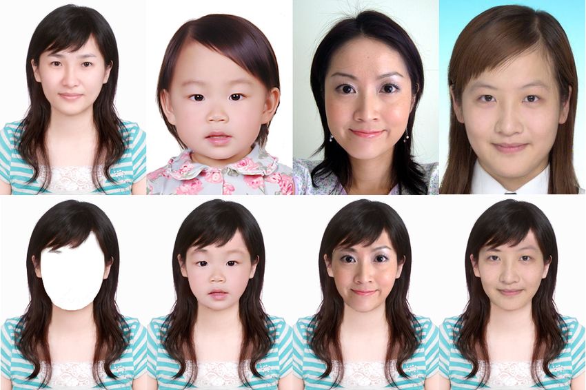
(a) Original images.          (b) Selected hairstyles.          (c) Website results.            (d) Our results.

Figure 1: Comparisons of our system with websites on hairstyle re-synthesis. The results are arranged in rows and the websites to be
compared with are http://thehairstyler.com, http://f.hair-demo.jp and http://hairtry.jp, respectively. Note
that the last 2 websites transform input images into 3D models, so the results may look a little bit different from the original images.
with the input face. However, previous approaches rarely offer a         Face detection plays a critical role in this work for finding the facial
flexible adjusting scheme that is both user-friendly and efficient for   contour, as well as for extracting the hairstyle from an input image.
the purpose of manipulation.                                             Hsu et al. [15], Yang et al. [35], and Kjeldsen et al. [16] introduced
                                                                         face detection methods that are based on skin color detection. Sev-
By assuming inputs to be 2D photos, our work successfully ad-            eral classic face detection algorithms have adopted machine learn-
dresses the aforementioned issues to achieve the desired function-       ing methods [31] [26] [25]. However, in this paper, recovering the
ality of hairstyle extraction and re-synthesis while striking a good     facial contour is more crucial than detecting the position of a hu-
balance between the involved user assistance and desirable con-          man face. Cootes et al. proposed the ASM method to extract an
vincing results. Generally speaking, the contributions of this paper     object contour from an input image [8]. Their algorithm first col-
can be summarized as the following. First, we adopt the existing         lects the information from many contours drawn explicitly by peo-
active shape model or ASM for short, to extract the facial con-          ple, finds out the rules or principles of object shapes based on the
tour from a given input photo. However, as ASM is not readily            gathered statistics, and finally derives object outlooks under differ-
applicable for detecting the upper facial contour, we further ex-        ent viewing angles or deformations. They later extended ASM to
tend its capability by fitting the missing facial contour portion with   focus particularly on the contour extraction of human faces and the
curves in concord with ASM’s extracted part. Second, we present          identification of facial features [7]. It is worth mentioning that, due
a novel skin texture synthesis scheme that could seamlessly fill in      to the obstruction of hair, normally ASM only extracts the lower
the missing skin details once the forehead region gets exposed after     facial contour, that is, the portion of facial contour that is lower
hair removal. Because the skin texture is non-stationary, traditional    than the eyebrows. As a consequence, new techniques are needed
texture synthesis method cannot be readily adopted. And due to           to recover the upper facial contour, which is especially needed in
the lack of information in the revealed forehead region after hair       this work.
removal, the approaches that simulate skin color/texture by com-
posing different skin channels and inpainting algorithms are also        A significant part of this paper is on the synthesis of forehead skin
undesirable. Our proposed method first generates an interpolated         after hair removal. For this purpose, there are two types of ap-
skin patch, and then we apply non-stationary texture synthesis to        proaches that could be adopted, image inpainting and texture syn-
obtain a skin patch based on the interpolated skin patch and the         thesis. In terms of image inpainting, Bertalmio et al. [2] used the
texture information from the input human face. Therefore, a more         information of the known region to impose boundary conditions
realistic and desired result can be derived. Third, we strive to au-     and derive the area to be inpainted by solving partial differential
tomate the whole process of hairstyle re-synthesis, including the        equations, or PDEs for short. Oliveira et al. [22] sped up the in-
identification of the entire facial contour, the recovery of revealed    painting process through image convolutions, while at the same
forehead region and the manipulation of fitting a hairstyle onto a       time providing results with comparable image quality. Pertain-
given face. In addition, fine-tuning the automated results is also       ing to texture synthesis, Efros et al. [12] employed a pixel-based
possible, while we have proposed a flexible, intuitive and efficient     method, that is, every pixel in the target texture is selected from the
adjusting scheme, so that the effort of user assistance could be re-     pixel in the source texture that bears the most similar neighboring
duced. Finally, our work also offers a much desired functionality        pixels. Wei et al. [34] later improved the texture synthesis perfor-
to perform the hair extraction from a photo, and the inclusion of        mance through a vector quantization scheme. By making use of
such functionality not only completes our proposed framework, but        a patch-based method, Efros et al. [11] synthesizing textures via
also opens up the possibility of a database construction for various     overlapped patches, where the transition among multiple patches
hairstyles. Results and user studies of our work are demonstrated        are smoothed by a graph-cut algorithm. There are also some ap-
to prove the effectiveness of our approaches.                            proaches that intrinsically combine both traits of image inpainting
                                                                         and texture synthesis, such as those methods proposed by Drori et
The rest of the paper is organized as the following. Section 2 re-       al. [10] for image completion and Sun et al. [29] for image com-
views previous literature related to this work. Section 3 describes      pletion with structure propagation. More specifically, Tsumura et
our proposed algorithms on recovering a facial contour, synthesiz-       al. proposed a skin synthesis scheme by decomposing a skin into
ing the forehead skin texture, extracting a hairstyle, and editing a     three channels: Melanin, Hemoglobin, and lighting, and a partic-
hairstyle. Section 4 demonstrates the generated results of our work.     ular skin type could be derived by a weighted sum of the three
Section 5 discusses the effectiveness of our proposed system with        channels [30]. Doi et al. applied a similar weighted scheme, which
some statistical analysis and user studies. Section 6 concludes this     is, however, mainly targeted for the synthesis of hand skin [9]. We
paper, addresses some potential limitations, and envisions possible      have to point out that, image inpainting techniques cannot be read-
future directions.                                                       ily applied to solve our problem, i.e., the forehead skin synthesis,
                                                                         as they are mainly designed for the situations where the area to be
                                                                         inpainted are locally small. On the other hand, texture synthesis
                                                                         methods cannot be easily adopted either, as the skin texture be-
2. RELATED WORK
                                                                         haves quite differently from local and stationary textures that have
There exist previous works related to this paper. Perhaps the most
                                                                         been properly dealt with. Moreover, the approaches in [30] and [9]
similar one is the patent by Blancato [4], where many similar func-
                                                                         synthesize a skin texture as a whole and therefore are not suitable
tionalities were proposed, except that nearly most of them need
                                                                         for the cases where a partial skin synthesis is required, unless the
manual assistance. Two interesting papers that can be viewed as
                                                                         corresponding channel weighting factors can be inversely and effi-
“indirectly” related to our work are the ones proposed by Blanz et
                                                                         ciently discovered at the run time. Recently Mohammed et al. [19]
al. [5] and Bitouk et al. [3]. Their work could exchange faces in two
                                                                         successfully tackled this issue in a different way. They collected a
images, and as a result two hairstyles get exchanged as well. How-
                                                                         certain amount of facial images to learn a probabilistic model. By
ever, strictly speaking, they achieve the purpose through swapping
                                                                         adapting a non-stationary image quilting method, the system could
facial features but not the entire faces. In this work, we propose a
                                                                         generate novel facial images which are not identical to any others
scheme that allows a user to change his/her face or hairstyle in a
                                                                         in the training data, together with the functionality to edit facial
user-friendly fashion.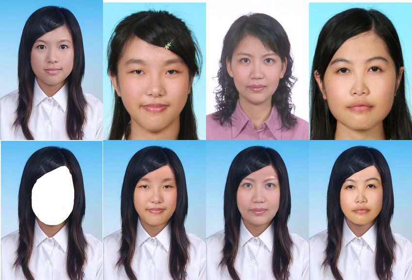
Figure 2: System overview of this work.

images. Though the second functionality is more related to what         by the user or automatically by our system.
is desired in this paper, the involved setup is nonetheless not very
trivial.                                                                The details of the involved steps will be covered in the following
                                                                        sub-sections. Section 3.2 shows how we identify the entire facial
Regarding hair extraction, in general it could be done through mat-     contour by extending the ASM algorithm. Section 3.3 describes
ting, including blue screen matting by Smith et al. [27], Baysian       the process of skin patch generation, so that the revealed forehead
matting by Chuang et al. [6], Poisson matting by Sun et al. [28],       region after hair removal can be recovered. Section 3.4 details
intelligent scissor by Mortensen et al. [20], soft scissor by Wang et   our algorithm to extract the hairstyle from a input image. Section
al. [32], and so on. However, to be able to apply these techniques,     3.5 demonstrates the abilities of our system to match an arbitrary
either special environment setup is mandatory, such as in [27], or      hairstyle onto an arbitrary face automatically as well as a flexible
an initial contour must be drawn, as in the rest of these methods.      and efficient adjusting mechanism to fine-tune the results if needed.
Instead, our approach requires much less user guidance for hair ex-     Section 3.6 discusses the replacement of partially/completely oc-
traction, and resorts to a more automatic segmentation approach         cluded ears with intact but somehow fake ears, while it oftentimes
that makes use of the color information from both hair and skin.        yields much more convincing results.

3. HAIR EXTRACTION AND RE-SYNTHESIS 3.2 Facial Contour Extraction
3.1 System Overview                 A facial contour consists of two parts, i.e., the lower contour, as
Figure 2 demonstrates our system overview. At first a 2D photo          shown in Figure 3(a), and the upper contour, as shown in Fig-
is given as the input, and the associated facial contour is detected,   ure 3(b). For detecting the lower contour, we simply apply ASM [7],
while in the mean time the corresponding hairstyle is extracted as      whose code can be downloaded from [1]. Figure 4 demonstrates
well. The detected facial contour is used to remove hair to obtain      the ASM process. Note that ASM not only extracts the lower con-
a 2D head without hair, termed bare head hereafter. The extracted       tour, but also other facial features as well, such as eyes and mouth,
hairstyle and bare head are added into the database. There are two      etc. The identification of these facial features is helpful to our skin
modes that a user can choose. First, the hair-less mode, where          texture synthesis process, which will be described later.
he/she can select a desired hairstyle from the database to be com-
posited with his/her bare head. The second mode is face-less mode,      As our task is to synthesize the revealed forehead skin after hair
where his/her face is removed and replaced by a selected face from      removal, it becomes necessary that we first recover the upper fa-
the database. Note that during the composition process, the selected    cial contour. In the initial state, as shown in Figure 5(a), let M ,
hair/head can be adjusted in terms of size and positions manually       N correspond to the left and right topmost pixels of the lower con-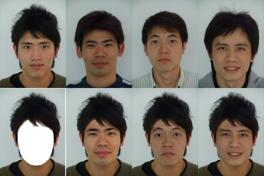
straint that the vertical position of J must not be lower than that of
                                                                         I or K, and if so, the vertical position of J is elevated to be the
                                                                         higher vertical position of I and K. On the other hand, assuming
                                                                         that both the vertical positions of I and K are lower than that of J,
                                                                         we move point I and K upwardly one pixel at a time. After each
                                                                         movement, we check whether the tangent directions of arc A and
                                                                         arc B at I (similarly arc B and arc C at K) align with each other
                                                                         or not, under the constraint that their vertical positions cannot be
                                                                         higher than that of J. The final result is shown in Figure 5(c). And
                                                                         the combined complete facial contour is shown in Figure 5(d).

           (a) Lower contour.          (b) Upper contour.

Figure 3: (a) The lower facial contour detected by ASM. (b)
The upper facial contour extracted by our proposed approach.

                                                                                               (a)                     (b)

                 (a)                             (b)

Figure 4: The ASM process. (a) The original image. (b) The
                                                                                               (c)                     (d)
resulting image after ASM applies.

tour as shown in Figure 3(a), and according to the ASM algorithm,        Figure 5: (a) The initial state of the upper facial contour detec-
normally these two pixels are vertically between the eyes and eye-       tion. (b) Refined upper facial contour concerning the revealed
brows. We next determine O and P such that M O = P N =                   skin pixels on the forehead region of the input image. (c) The
1
  M N , and thus OP = 12 M N . Note that the horizontal positions        final result after smoothing the connecting points I and K. (d)
4
of I and K are the same as O and P , respectively. The vertical          The entire facial contour detected by our system.
positions of I and J are set to be above the right eyebrow and the
left eyebrow, through the help of ASM. According to [21], a human        There are two technical issues worth mentioning. First, the con-
face could be divided vertically into 3 distinct thirds, which are the   tour extraction process may not be always accurate. When ASM
hairline to the eyebrows, the eyebrows to the base of nose and the       does not do a perfect job, user assistance may be required to ad-
base of nose to the bottom of the chin, respectively. We refer J as      just the detected lower facial contour. As can be seen from the
the hairline of a human face. Thus, we can then derive J’s vertical      previous contour detection process, the main purpose of the lower
position accordingly. And J’s horizontal position is determined as       facial contour detection is for the extraction of facial contour, and
the midpoint between O and P . By making use of the position of          in particular, the determination of the positions of M and N , and
O, and treating M O and OI as the minor radius and major radius          thus the derivation of other crucial points and curves. Second, the
of an ellipse, a quarter arc on the circumference of the ellipse, de-    upper facial contour does not need to be very accurate, as in most
noted by A, could be derived, and so could arc C. On the other           of the situations the forehead of an input photo is blocked by hair
hand, arc B represents a half arc on the circumference of the el-        anyway. Therefore as long as the shape of the proposed contour
lipse that is determined by I, J and K. That is, the minor radius        looks reasonable, it should not cause any serious problems. Most
and major radius of this ellipse are 12 IK, and the distance between     importantly, even in the case where a head without or with little
                                                                         hair is encountered, our proposed algorithm can still perform its job
J and the line segment IK, respectively. So the initial setup for the
                                                                         satisfactorily. In our implementation, an adjustment mechanism is
upper facial contour has been done, as shown in Figure 5(a). We
                                                                         provided to let the user to fine-tune the final result of the detected
now move I and K upwardly to finish the process of upper facial
                                                                         facial contour. As shown in Figure 6(b), the original detected fa-
contour detection. For I, we start from every pixel lying on arc
                                                                         cial contour does not fit the person’s face very well. In this case, the
A, and we search upwardly until meeting the first non-skin pixel.
                                                                         user can adjust the facial contour by simply dragging any of the fea-
Then the vertical position of I is set to be the highest vertical po-
                                                                         ture points ( blue rectangles) to a more proper position, so that the
sition found. The vertical position of K is determine in the same
                                                                         adjusted facial contour might be desirable to the user. An adjusted
fashion but starts with arc C. However, as shown in Figure 5(b),
                                                                         and potentially more desired result can be seen in Figure 6(c).
as I and K are discovered independently, it is not necessary that
the three arcs join smoothly at the connecting points I and K. We
resolve this by the following procedures. We first enforce the con-      3.3     Skin Synthesis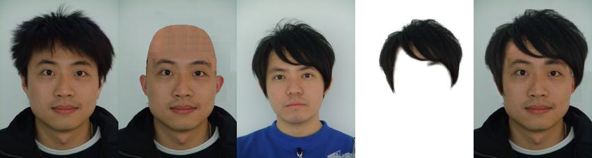
just mentioned. Figure 7(e) and Figure 7(f) demonstrate the result-
                                                                          ing bare head images without and with the aforementioned texture
                                                                          synthesis process, respectively.

          (a)                      (b)                     (c)

Figure 6: (a) The original image. (b) Facial contour detected
by our system. (c) Facial contour fine-tuned by the user.
                                                                                (a) Skin texture to extract.        (b) Skin base color.

Once a complete facial contour is extracted, the next step is to syn-
thesize a patch of skin texture on the resulting hole region after hair
removal. Due to the normally very limited available information,
as oftentimes other skin portions may be blocked by hair, we first          (c) Linearly interpolated skin.    (d) Texture synthesized skin.
make a seemingly bold assumption that the forehead skin texture
is very similar to the skin portion below the eyes and above the
mouth, as can also be observed from the regions marked in red in
Figure 7(a). And through the help of ASM, the search for such
a rectangular area could be easily accomplished without difficulty.
However, as region B includes the nose, thus resulting a lighting
situation that may be different with other regions, such as regions
A and C. To resolve this, we artificially regenerate the skin tex-
ture in region B as follows. First, we convert all the colors from
the RGB color system into the CIELAB color system, so that a
more decorrelated chrominance and luminance distribution could
                                                                            (e) Without texture synthesis.      (f) With texture synthesis.
be obtained. Note that the CIELAB color system consists of L,
a and b channels, where L is related to luminance and a, b are re-        Figure 7: Our skin synthesis process. (a) The skin texture,
garded as the information for chrominance. Second, we calculate           marked in red, that is to be extracted and used to synthesize
the average a and b values for the pixels in regions A and C. These       the forehead skin. (b) The base color used for skin synthesis.
averaged a and b values are combined to derive the base color for         (c) The linearly-interpolated skin. (d) The texture synthesized
ensuing skin synthesis, as shown in Figure 7(b). Note that for dis-       skin based on (c). (e) The resulting head with hair removal
playing purpose, the L channel for the color shown in Figure 7(b)         and forehead skin recovered without texture synthesis. (f) The
is temporarily set to be the highest L value in regions A and C, as       resulting head with hair removal and forehead skin recovered
this skin color will eventually be replaced by the final synthesized      with texture synthesis.
skin color in the next step. The base skin color serves as the basic
chrominance value for all the skin pixels to be synthesized within
these three regions, and the L values, or the luminance values, for       3.4      Hairstyle Extraction
these pixels are then linearly and horizontally interpolated between      We perform hairstyle extraction by making the following assump-
the pixels on the (one pixel wide) brightest column in region B, and      tions. First, the background color is simple, and should not interfere
the pixels in regions A and C. Here the brightest column means the        with the detection of skin, hair and clothes. Second, there should
column containing the brightest pixel, where the nose tip usually re-     be enough hair for the purpose of detection, and there should be
sides. Third, divided by the brightest column in region B, the area       presumably some hair above the head. Third, the hair color should
to the left of the brightest column is linearly interpolated using the    be distinguishable from the color of the clothes. If all these re-
rightmost column of region A, while the area to the right is linearly     quirements are satisfied, we proceed with the hairstyle extraction
interpolated with the leftmost column of region C. To smooth the          by dividing an input image into four segmented regions, including
potentially inconsistent transition on the brightest column, and also     skin, hair, background, and clothes by the following process. First,
to counteract the effect of excessive lighting for originally being the   we define the polygon to represent the facial shape by using the set
nose region, we further apply the technique of Poisson image edit-        of points from the 0th to the 14th derived from ASM, as shown in
ing [23] around this region, and the result is shown in Figure 7(c).      Figure 4(b). Within the facial shape, we discard the pixels within
For each pixel within region A, B, and C, once all its three channel      the facial feature boundaries detected by ASM. For the remaining
CIELAB values are determined, its color representation could be           pixels, as the non-black area shown in Figure 8, we calculate their
converted back to the RGB color system. Finally, by making ref-           statistical mean to obtain an average skin color estimation. Sec-
erence to region A and C in Figure 7(a), and using the region of          ond, we calculate the average pixel color from the pixels in the
the linearly interpolated result in Figure 7(c) as the base texture,      topmost row on the image and treat it as the initial background
we perform the final texture synthesis process to derive the result       color. Third, by finding the average color from the pixels in the
shown in Figure 7(d). Note that to avoid odd transition between the       area immediately above arc B in Figure 5(c), we could roughly get
synthesized forehead and the lower known facial region, Poisson           the hair color. Fourth, we compute the pixels in the last row, and
image editing is again adopted during the texture synthesis process       their average is used to derive the base color for the clothes. Fi-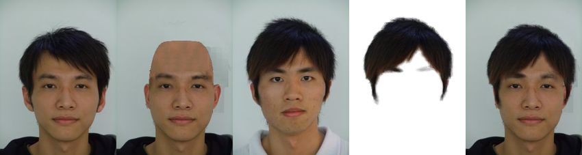
nally, once all four average colors are defined, we then use the four
colors as the initial seeds and apply the K-means approach [18] to
iteratively cluster the input image into the final four segmentations,
as shown in Figure 9(b). Note that, the main purpose of applying
the K-means algorithm is to distinguish the color distribution of the
hairstyle from others, so that we could make sure that no non-hair
pixel is mis-classified into the hair cluster.

                                                                               (a) Original image.        (b) The color segmentation result.

Figure 8: The mask for calculating the skin color distribution.
                                                                            (c) The generated trimap.          (d) The extracted hairstyle.
Next, for the ensuing matting purpose, we generate a trimap by
the following process based on the aforementioned segmentation                          Figure 9: The hair extraction process.
result. First, we find the connected component that intersects with
arc B in Figure 5(c) through a very efficient run-based two-scan
labeling algorithm proposed by He et al. [14]. Second, we per-
form the erosion operations borrowed from morphology [13] on
the component, where the involved mask is a 11 × 11 mask, to
derive the white region shown in Figure 9(c). Note that, the sizes
of most of the images in our database are 240 pixels in width and
320 pixels in height. Therefore, the size of the morphology mask
should be adjusted depending on the size of the input image. Third,
we perform another morphology operation, the dilation operation
with the same mask also on the largest component to obtain the                       (a) Original hairstyle.    (b) Scaled hairstyle.
gray region shown in Figure 9(c). Note that due the properties of
these two operations, the gray region must contain the white one,         Figure 10: (a) The original hairstyle with initial control points.
which for demonstration purpose is drawn on top the gray region.          (b) The scaled hairstyle with control points moved.
Forth, by subtracting the white region from the gray one, we could
then generate a trimap to be sent to a matting process to extract
the hairstyle, as shown in Figure 9(d). Here for matting we resort        For manual matching, our interface is shown in Figure 10(a). As
to Levin et al.’s closed-form matting [17] as it performs quite well      can be seen in this figure, there are five control points, marked in
and its implementation source code is available. Note that, for the       blue, to scale a given hairstyle. The lower right control point is a
ensuing operations, in addition to extracting the desired hairstyle       global scaler, that is, its movement will cause the hairstyle to scale
from an image, we also need to generate a bare head image from            uniformly with respect to the reference point. On the other hand,
the input photo. This is essentially the background recovery pro-         the upper and lower two control points will only affect the upper
cess, which is achieved by first removing the gray region from the        and lower vertical scales, respectively, and similarly for the left and
input image, then texture synthesizing the resulting holes, and fi-       right control points to scale horizontally, as shown in Figure 10(b).
nally pasting back the previously synthesized bare head as shown          Note that the result shown in Figure 10(b) cannot be easily achieved
in Figure 7(f).                                                           by merely using the global scaler.

3.5 Hairstyle Editing                                                     For automatic matching, the basic idea is to automatically scale a
All the previously mentioned processings are for the preparation of       given hairstyle properly so that there exists no holes between hair
the final stage, that is, the hairstyle re-synthesis. In other words, a   and head. To meet these desired requirements, we define an energy
user can freely select a desired hairstyle from the database and our      function as the following:
system could be used to match a selected hairstyle with a bare head,                                    E = Ehole                             (1)
obtained from previous steps. To allow maximal flexibility, our sys-
tem offers two matching modes, automatic and manual. However,             where Ehole represent the number of hole pixels that the hairstyle
for both modes, our system first tries to locate the reference points     intersects or generates. Here the number of hole pixels is counted
on the hairstyle, which are later used to aligned with M , J and N        by the number of facial contour pixels above the mouth that are
in Figure 5, so that the initial position of a given hairstyle can be     adjacent to a hole. These contour pixels are marked in red in Fig-
determined. In the case where the hair extraction is done by our          ure 11, where the green line denotes the lower bound of facial con-
system, the reference points’ location are already known. Notice          tour that we put into consideration. A hole can be detected by
that all the scaling operations mentioned hereafter are assumed to        checking if it is with the background color and gets enclosed by
be with respect to the reference points.                                  either skin or hair pixels. It is thus apparent that reducing these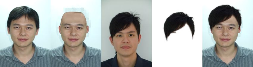
given face, we pick one pair of the manually extracted ears which
                                                                         have similar luminance value to the input face. For each pair of the
                                                                         manually extracted ears, we compute its distance to the input face
                                                                         in the L channel of the CIELAB color space as the following:
                                                                           Dear,f ace =    Z(f ace, lef t ear) + Z(f ace, right ear),
                                                                                                                   µx −µy       µy −µx
                                                                                             where Z(x, y) =         σy
                                                                                                                            +     σx
                                                                                                                                            (2)

                                                                         The symbol µ computes the mean values, in L channel, of the ex-
                                                                         tracted left ear , extracted right ear or the input face, while symbol
Figure 11: The searching range for detecting undesired holes.            σ refers to the standard deviation. Z(x, y) sums up the distance,
                                                                         similar to the Z-value or standard score in statistics, between the
                                                                         mean value of the extracted ear and the distribution of the input
                                                                         face, and the distance between the mean value of the input face
                                                                         and the distribution of the extracted ear. After a pair of ears with
                                                                         the most similar luminance, with respect to the input face, have
                                                                         been chosen, the possibility of inconsistency in luminance between
                                                                         the ears and the face still exists. Therefore, we make a luminance
                                                                         adjustment on every pixel of the selected ears by simply transform-
                                                                         ing the ears’ luminance distribution into the face’s. The following
                                                                         equation shows the adjustment on one pixel:
                     (a)                     (b)                                                                       σf ace
                                                                             earadjusted = (earoriginal − µear ) · (          ) + µf ace    (3)
                                                                                                                       σear
   Figure 12: (a) Automatic example. (b) Manual example.

numbers, or equivalently the energy term, could lead to a better
placement of the hairstyle.

With the energy function being defined, our system automatically
and iteratively adjust the hairstyle as follows. In each iteration, we
always check to see if any vertical or horizontal scaling operation
can lower the total energy, and if so, scaling operation should be
performed vertically or horizontally, depending on which scaling
operation can lower the total energy more. Once a scaling opera-
tion is performed, the current iteration ends, and the next iteration
starts. However, in the case where no scaling operation can lower
the total energy, we move the hairstyle as a whole, and this indi-                              (a) The original photo.
cates the mapping between the hairstyle’s reference point and J
(in Figure 5) on the bare head should be modified as well, and the
current iteration also finishes. Note that no matter for scaling or
translation, the probe for lower energy is simply a trial on a po-
sition’s four neighboring pixels: upper, lower, left, and right, and
the position/operation that could further minimize the total energy            (b) The extracted left ear.   (c) The extracted right ear.
is selected/performed. As shown in Figure 12, our automatic ad-
justing scheme can generate results that are comparable with the                      Figure 13: The ear extraction process.
ones that are done manually. For face swapping, the involved align-
ment becomes much easier as the corresponding ASM information            The final stage is to synthesis the ears onto the input face. To fa-
is available.                                                            cilitate the ensuing ear synthesis process, during our manual ear
                                                                         extraction process just mentioned, we also manually marked the
                                                                         two contacting positions that an ear connects to its original facial
3.6 Ear Synthesis                                                        contour. Figure 14 demonstrates an example of such an alignment
Through numerous experiments and user feedback, we have found            process. In Figure 14(a), the ears are to be aligned with a new facial
that the synthesized results often look weird if the ears are removed.   contour, where we mark the connecting portions of the ears in red,
Or, if the remaining ear pixels are preserved after hair removal, the    and the connecting portions are the lines connecting the aforemen-
fragmented ears could be a distraction, or even sometimes make           tioned contacting positions. On the other hand, the connecting por-
people taking more focus on the artifact near the ear region instead     tions on the new facial contour, marked blue in the same Figure, are
of the simulation result of swapping the hairstyle. Also, the users      determined by the following steps. First, according the bounding
said that it is more perceptually acceptable if the fragmented ears      boxes of an ear’s original facial contour and the new facial contour,
are replaced with suitable ones. However, it is evident that like hair   the ear is first scaled in width and height. Second, we adjust an ear’s
extraction, ear extraction is also not trivial especially when a long    position so that its boundingbox’s midpoint aligns vertically with
hairstyle is encountered. To cope with this, we manually extract         the boundingbox of the new facial contour. Third, we horizontally
the ears from some photos, as shown in Figure 13. And for any            move an ear until its bottommost point touches the facial contour,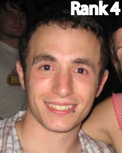
as shown in Figure 14(a), and this also determines the lower point tos’ faces, respectively. On the other hand, Figure 22(f) and Fig-
on one of the connecting portions on the facial contour. Fourth, the ure 22(g) show our hairstyle swapping results, while Figure 22(h)
upper point on the facial contour is decided by horizontally pro- and Figure 22(i) our face swapping results. As can be seen from
jecting the top of the ear’s boundingbox onto the facial contour. Fi- these figures, our face swapping and hairstyle swapping capabili-
nally, we calculate the angle between the two connecting portions, ties are more like dual operations to each other, and we believe such
approximated by lines and perform a rotation accordingly to finish pairing operations would be more useful for facial appearance alter-
the alignment process. Note that for the demonstration purpose, in ation. However, We also have to point out that, for the cases where
Figure 14(a) we in fact have intentionally rotated the original ex- the involved models contain complex or ambiguous backgrounds,
tracted ears from Figure 13(b) and Figure 13(c) to denote the cases the hairstyle extraction process may be semi-automatic, that is, user
where the formed angles between two connecting portions may not assistance may be required. For example, In Figure 22(a), the hair
be small. Nevertheless, after a proper alignment process, the de- and background are too similar to be automatically separated. Even
sired result can be achieved, as shown in Figure 14(b). In fact, though we manually generate the tri-map for the source image,
the synthesis results after attaching “fake” ears have often become some artifacts still exist in the extracted hairstyle result, thus mak-
much more convincing than they were before, as will be shown in ing the synthesized images less natural. It is especially obvious in
the Results Section. the background of Figure 22(g) and in the upper right region of the
left eyebrow in Figure 22(h), Also note that, in Figure 22(f) and
Figure 22(g) the words Rank 1 and Rank 4 are occluded by the hair
whereas they are not in Figure 22(d) and Figure 22(e). This is due
to fact the extracted hairstyle is from Figure 22(a) and it is pasted
onto the target photos to make part of the words of Rank 1 and Rank
4 invisible. Nevertheless, all the other hairstyle extraction results
presented in this paper are done automatically.
As a final note, currently we do not compare our work with Mo-
hammed et al.’s work [19] for the following two reasons. First, their
(a) Before ear alignment and (b) After ear alignment and work exchanges part of the facial features, while ours exchanges
luminance adjustment. luminance adjustment. the entire head. Second, their algorithm arbitrarily chooses sample
patches for the skin texture synthesis, so that the results may not be
Figure 14: The ear alignment process. controllable.
4. RESULTS 5. DISCUSSION
Our experiments are conducted on a machine with a Intel Core 2 As one of the most important contributions of this work is to re-
1.86GHz CPU and 3GByte memory, running on MS Windows XP. cover the skin of the revealed forehead region, so that the results
The involved programming language is Visual C++, and the Pois- might be more desirable after putting on new hairstyles. We wish
son equation is solved by MATLAB 7.0. In terms of timing, it to measure how this feature is being needed. In our current im-
usually takes 3 to 5 seconds to derive a bare head model, and the plementation, we synthesize a skin patch for replacing the entire
automatic hairstyle adjusting scheme requires less than 3 seconds forehead region no matter which pixels in the forehead region have
to converge on an average. been occluded by hair. After wearing on a newly selected hairstyle
for the input image, we can divide the forehead region into 3 parts.
As shown in the Introduction section by the Figure 1(c), failure to The first part consists of the pixels occluded by the new hairstyle.
remove the original hair may cause severely undesired effect. On Since these pixels do not affect the quality of the final result, we
the contrary, after proper hair removal, our system can provide a simply ignore them. The second part refers to the pixels that are
more pleasing result, as shown in Figure 1(d). considered hair pixels in the input image but are not covered by the
new hairstyle. We should definitely take special care on theses pix-
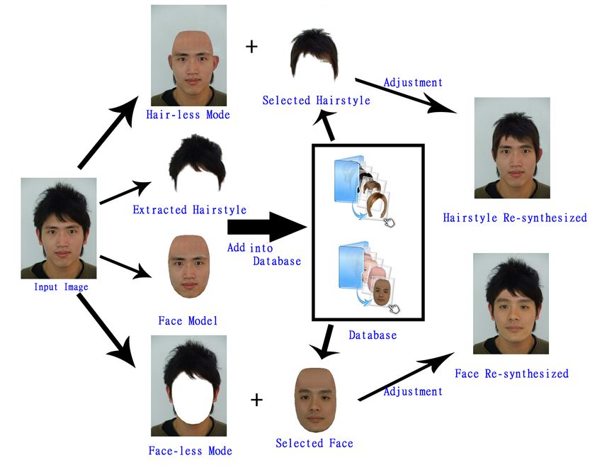
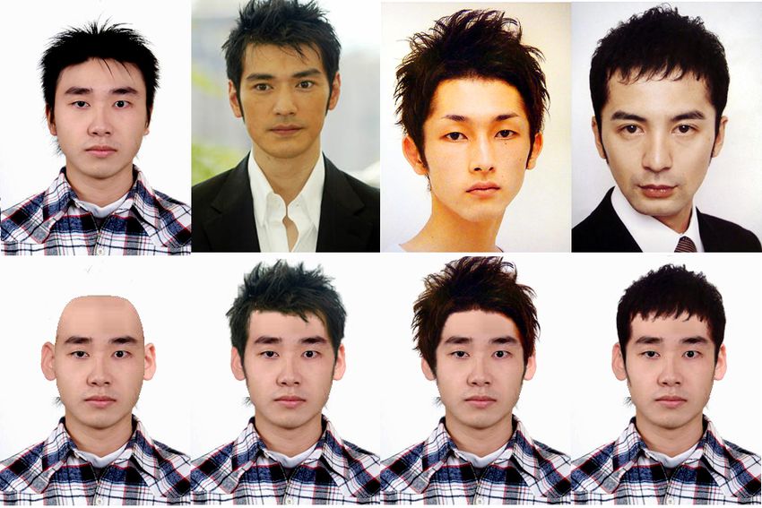
Figure 15, Figure 16, Figure 17, Figure 19, Figure 20 and Figure 21 els, or they may induce prominent artifact to the final result. Such
demonstrate the effectiveness of our system by testing many cases examples can be seen in the third column of Figure 1. Finally, the
on face and hairstyle swapping. Note that due to various original rest of the pixels are those who are considered skin pixels in the in-
skin colors or lighting conditions, the extracted hairstyle may not put image and are not occluded by either the original hair or the new
be very clean, as shown in Figure 19, thus leading to the undesired hairstyle. We then analyze the statistical data from (f), the automat-
color bleeding effects along the hair boundary. A more uniform or ically optimized results, and (g), the manually manipulated results,
controlled lighting setup would greatly help improve the results, as shown in Figure 15, Figure 16 and Figure 17. The collected num-
shown in Figure 15, Figure 16 and Figure 17. bers are listed in Table 1. To ease the discussion, we use symbol A
as the total number of revealed forehead pixels, which combines the
Moreover, as we have mentioned previously, unlike the work pro- pixels in the second part and the third part of the forehead region as
posed by Bitouk et al. [3], our results in Figure 20 and Figure 21 we have mentioned above, and symbol B for the number of pixels
demonstrate our unique capability of altering not only the facial in the second part of forehead region. Therefore B/A means the
features, but the entire facial contour as well, to achieve sometimes percentage of the hair pixels of the input image, which may induce
more desirable face-off results. To show more concrete examples, serious artifact if we do not take care of, in the revealed forehead
we try to compare our results with those from Bitouk et al.’s work in region. It is evident that the values of B and B/A could be referred
Figure 22. Figure 22(a), Figure 22(b) and Figure 22(c) are a source as how much the feature of recovering the forehead region is being
photo and two target photos from Bitouk et al.’s work [3], respec- needed. As can be seen in Table 1, the percentages of the neces-
tively, while Figure 22(d) and Figure 22(e) are their face swapping sarily recovered pixels in our examples range from 60% to 80%
results by replacing the source photo’s face with the target pho- and the number of the necessarily recovered pixels range from 300
(a)                            (b)                              (c)                           (d)                          (e)

             (f)                            (g)                              (h)                           (i)                          (j)

Figure 15: An example on changing one’s hairstyle into another with different algorithms. (a) Input image. (b) Bare head image
generated by our system. (c) The hairstyle model. (d) The hairstyle extracted from the model. (e) Initial state of resynthesizing the
hairstyle (d) onto the given face (a). (f) The re-synthesis result optimized by our system. (g) The re-synthesis result adjusted manually.
(h) The re-synthesis result without dealing with the fragmented ears. (i) The re-synthesis result by removing the fragmented ears.
(j) The re-synthesis result by just simply attach the new hairstyle onto the face without making any modifications on the forehead
region and the ears. Images (e) (g) will be used in our analysis and user studies in the Discussion Section.

to 600, which implies the recovery of the revealed region is pretty                column of each testing set, where we simply match the correspon-
much being needed. Furthermore, notice that, the result should has                 dences between the reference points of an extracted hairstyle and
been evaluated case by case. For example, if a man with a hairstyle,               the reference points of a input face, it takes more than 15 seconds
which covers almost the whole forehead region. And he would like                   in average for the users to make their adjustments. And after our
to get a haircut with a closely cropped hairstyle. In this situation,              proposed automation mechanism, it saves nearly half of the time
the functionality of recovering the revealed forehead region is def-               for adjustment in average. In the case of Figure 15, the improve-
initely desired, because we can hardly neglect the uncorrected hair                ment is even more significant, while half of the subjects thought
pixels after wearing on the new hairstyle.                                         that the final results yielded from our system need no further ad-
                                                                                   justment. An interesting phenomenon is also observed in this user
We have also conducted a user study to verify that our proposed                    study as well. Once a user decides to move a hairstyle’s position
method indeed reduces the user assistance during the hairstyle swap-               or to change a hairstyle’s size, there are oftentimes two notable
ping process. We invite 12 subjects to participate this study. And                 outcomes. First, a user may just try to probe for a better configura-
there are 3 testing sets, 6 images in total, in the user study, which are          tion for the hairstyle, but suddenly found that the original setup is
images (e) and (f) of Figure 15, Figure 16 and Figure 17. For each                 quite acceptable for him/her. Thus, he/she would stop the adjusting
testing set, image (e) refers to the image that the hairstyle is initially         process immediately. Such cases are the ones that the timings are
located by the reference points, while image (f) represents the auto-              under 5 seconds (included) in Table 2. Second, a user may end up
matic hairstyle re-synthesis result. We ask the participants to check              spending lots of time on fine-tuning, even though the change is not
the images to see whether he/she thought that the hairstyles are be-               easily perceivable. Sometimes, the fine-tuning process could take
ing positioned at the right place or not. He/she can use our system                up to more than 10 seconds.
to scale the hairstyles to the right scale or move to the right loca-
tion. And then, we record the elapsed seconds that the users take to               Knowing that recovering the revealed forehead region a being needed
adjust the results. Table 2 shows the records where zeros indicate                 feature and our proposed mechanism indeed reduces the user assis-
the cases where the adjustments are considered unnecessary. Ac-                    tances to some extent. We would like to further measure the qual-
cording to the user study, it is apparent that our proposed approach               ity of our simulated results, i.e. to compare our results with the
reduces user assistance in editing a hairstyle into an appropriate                 ones that do not take good care of the revealing hair pixels, and to
one. As the timings shown in Table 2, the numbers in the right                     evaluate the users’ acceptance level of our hairstyle re-synthesis re-
(a) (b) (c) (d) (e)
(f) (g) (h) (i) (j)
Figure 16: The second example on changing one’s hairstyle. The configuration is the same as Figure 15.
(a) (b) (c) (d) (e)
(f) (g) (h) (i) (j)
Figure 17: The third example on changing one’s hairstyle. The configuration is the same as Figure 15.Table 1: The statistical data for analyzing how much the feature of recovering the pixels in the forehead region is being needed.
Number of revealed forehead pixels Hair pixels in the input image but Percentage (%) of pixels that
after putting on new hairstyle. (A) are not covered by the new hairstyle. (B) may induce obvious artifact. (B/A)
Fig. 15(f) 688 522 76%
Fig. 15(g) 820 614 75%
Fig. 16(f) 418 319 76%
Fig. 16(g) 556 338 61%
Fig. 17(f) 475 381 80%
Fig. 17(g) 453 359 79%
Table 2: The timing results, measured in seconds, for the first user study. In each testing set, e.g. Figure 15, Figure 16 or Figure 17,
the left column records the adjusting times for (e), the cases of the automatically matched hairstyles, and the right column records
the adjusting times for (f), the cases of the initially located hairstyles. The numbers in the last row show the average adjusting time
for each testing set.
User Fig. 15(e)-auto Fig. 15(f)-manual Fig. 16(e)-auto Fig. 16(f)-manual Fig. 17(e)-auto Fig. 17(f)-manual
1 0 18 12 16 13 30
2 0 5 0 7 15 15
3 0 17 12 14 11 17
4 5 14 8 8 5 16
5 0 26 0 13 12 20
6 12 6 7 8 4 7
7 15 20 15 25 16 19
8 0 6 0 12 0 8
9 13 23 23 18 15 24
10 0 5 8 8 8 18
11 17 27 19 38 13 32
12 7 19 0 16 11 14
average 5.75 15.5 8.67 15.25 10.25 18.33
Figure 15 Figure 16 Figure 17
(g)
(h)
(i)
(j)
Figure 18: The collected scores of the acceptance levels that the users gave to the four different hairstyle re-synthesis results, while
higher scores can be referred as higher acceptance levels. Row (g) presents the scores given to the results with fake ears and syn-
thesized forehead. Row (h) presents the scores given to the results with synthesized forehead and preservation of the original but
fragmented ears. Row (i) presents the scores given to the results with synthesized forehead but removal of the ears. Row (j) presents
the scores given to the results without making any modifications to the original images.sults. As mentioned in Section 3.6, distractions may happen if the or even the eyes cannot be handled properly in this paper, as shown
regions near the ears are not handled properly. Hence, in this eval- in Figure 23(b). Third, if the background contains complex color
uation, we include four kinds of simulated results for each hairstyle patterns or the hair color is close to that of the clothes, segmentation
re-synthesis comparison, as shown from (g) to (j) in Figure 15, Fig- errors may occur, thus leading to erroneous results as can be seen
ure 16 and Figure 17. There are 46 subjects invited to provide their in Figure 23(c).
opinions, and three testing sets of images are demonstrated to each
participant. Each testing set contains an original image, a hairstyle In the future, in addition to addressing aforementioned limitations,
image that is to be exchanged and four hairstyle re-synthesis out- there are several directions that we want to pursue. First, more
comes, which are (g) the result with fake ears and synthesized fore- fine-grained hairstyle editing functionalities, other than just scaling
head, (h) the result with synthesized forehead and preservation of and translation, are desired. A good example of such is the ap-
the original but fragmented ears, (i) the result with synthesized proach proposed by Wang et al. [33], but it is mainly used in 3D
forehead but removal of the ears, and (j) the result without mak- cases. Second, we currently have not performed proper ear extrac-
ing any modifications to the original image. The four hairstyle re- tions but resort to a compromised version by combining results with
synthesis outcomes are shown to the participants in random orders. “fake” ears. The results look reasonably well but still not perfect.
And the following introductions are given: We have provided four Finally, the aesthetic factor may be put into concern. For example,
methods to achieve the goal of replacing one’s current hairstyle given a face, a system could automatically select a hairstyle from
with another in a single image. However, there exist different kinds the database that forms the best match, in terms of attractiveness.
of artifacts in each of them due to various reasons. We want to know
which of the artifact makes the least impact on distracting people 7. REFERENCES
from perceiving the result of a hairstyle replacement. Or, regarding [1] Active Shape Models with Stasm.
them as simulated hairstyle swapping results, how do the artifacts http://www.milbo.users.sonic.net/stasm/,
affect your imagination on the hairstyle exchanging results. Then, 2008.
the users are inquired to give every result a score of a seven-level
(seven-point) Likert scale, while lower points mean bigger distrac- [2] M. Bertalmio, G. Sapiro, V. Caselles, and C. Ballester. Image
tions or lower acceptance levels. The scorings are collected and Inpainting. In SIGGRAPH ’2000, 2000.
shown in Figure 18, as different colored bars represent different
scores that the users gave. It can be easily observed that the scor- [3] D. Bitouk, N. Kumar, S. Dhillon, P. Belhumeur, and S. K.
ings of our results, with fake ears and synthesized forehead, shown Nayar. Face Swapping: Automatically Replacing Faces in
in row (g), apparently outperform the others. In each testing set, its Photographs. ACM Transactions on Graphics (Also Proc. of
averaged rating is significantly higher than any of the others. And ACM SIGGRAPH ’2008), 27(3):1–8, 2008.
if we set 5 point as a dividing boundary, it has been given 5 point
or above by more than half of the participants in each testing set, [4] V. Blancato. Method and Apparatus for Displaying
while the results of the other three methods do not perform so well Hairstyles, 1988. US Patent 4731743.
under this standard. Moreover, we cannot comment that which of
the other three methods is better since their scoring distributions [5] V. Blanz, K. Scherbaum, T. Vetter, and H. Seidel.
are unstable through the three testing sets. For example, in the first Exchanging Faces in Images. In Eurographics ’2004, 2004.
testing set, i.e. Figure 15, (j) is considered having higher quality
[6] Y. Y. Chuang, B. Curless, D. H. Salesin, and R. Szeliski. A
than (h), but it turns out to be the opposite situation in the third
Bayesian Approach to Digital Matting. In In Proceedings of
testing set, i.e. Figure 17.
CVPR 2001, pages 264–271, 2001.
6. CONCLUSIONS AND FUTURE WORK [7] T. F. Cootes and C. J. Taylor. Statistical Models of
We have proposed methods to automatically perform hair removal, Appearance for Medical Image Analysis and Computer
hairstyle extraction, and face/hairstyle swapping for 2D images. Vision. In SPIE Medical Imaging, 2001.
Our system has its strengths on successfully fitting a reasonable
forehead shape and on re-synthesizing the skin texture for the re- [8] T. F. Cootes, C. J. Taylor, D. H. Cooper, and J. Graham.
vealed forehead after hair removal. A hairstyle extraction algorithm Active Shape Models - their Training and Application.
is developed, and a user-friendly head/hairstyle adjusting scheme Computer Vision and Image Understanding, 61(1):38–59,
is proposed to facilitate some possible manipulations for hairstyle 1995.
cloning. An automatic adjusting scheme is also introduced to fur-
[9] M. Doi and S. Tominaga. Image Analysis and Synthesis of
ther increase the efficiency for the cloning on different hairstyles.
Skin Color Textures by Wavelet Transform. In Image
Some analysis and user studies have been conducted, and the sta-
Analysis and Interpretation ’2006, pages 193–197, 2006.
tistical numbers of the analysis and the user studies demonstrate
the effectiveness of our system on reducing the user assistances in [10] I. Drori, D. Cohen-Or, and H. Yeshurun. Fragment-based
hairstyle adjustment as well as providing more convincing hairstyle Image Completion. In SIGGRAPH ’2003, pages 303–312,
re-synthesis results. 2003.
There are, however, several limitations in our current system. First, [11] A. A. Efros and W. T. Freeman. Image Quilting for Texture
we are not able to recover the texture or shape of the clothes or Synthesis and Transfer. In SIGGRAPH ’2001, pages
human neck which are occluded by the hair. An example is shown 341–346, 2001.
in Figure 23(a). Second, our skin synthesis algorithm is based on
the patch in the lower known facial region, so the smoothness of the [12] A. A. Efros and T. Leung. Texture Synthesis by
lower known facial region affects the skin synthesis result. Also, Non-parametric Sampling. In International Conference on
for the cases where the hair is long enough to occlude the eyebrows Computer Vision, pages 1033–1038, 1999.Figure 19: More examples on changing hairstyles. The leftmost column, from top to bottom, shows the original input image and its
corresponding bare head result. The other three images in the first row are the models whose hairstyles are extracted and then used
to resynthesize with the input image. The other three images in the second row are the final hairstyle resynthesized results.
[13] R. C. Gonzalez and R. E. Woods. Digital Image Processing. Controversy. American Journal of Orthodontics and
Prentice-Hall, New York, second edition, 2002. Dentofacial Orthopedics, 130(3):277–282, 2006.
[14] L. He, Y. Chao, and K. Suzuki. A Run-Based Two-Scan [22] M. M. Oliveira, B. Bowen, R. McKenna, and Y. Chang. Fast
Labeling Algorithm. IEEE Transactions on Image Process, Digital Image Inpainting. In VIIP (International Conference
17(5):749–756, 2008. on Visualization, Imaging and Image Processing) ’2001,
[15] R. L. Hsu, M. Abdel-Mottaleb, and A. K. Jain. Face 2001.
Detection in Color Images. IEEE Transactions on Pattern
[23] P. Perez, M. Gangnet, and A. Blake. Poisson Image Editing.
Analysis and Machine Intelligence, 24(5):696–706, 2002.
In SIGGRAPH ’2003, pages 313–318, 2003.
[16] R. Kjeldsen and J. Kender. Finding Skin in Color Images. In
FG’ 96 (2nd International Conference on Automatic Face [24] D. I. Perret, K. A. May, and S. Yoshikawa. Facial Shape and
and Gesture Recognition), 1996. Judgments of Female Attractiveness. Nature,
368(6468):239–242, 1994.
[17] A. Levin, D. Lischinski, and Y. Weiss. A Closed-Form
Solution to Natural Image Matting. IEEE Transactions on [25] H. A. Rowley, S. Baluja, and T. Kanade. Neural
Pattern Analysis and Machine Intelligence, 30(2):228–242, Network-Based Face Detection. IEEE Transactions on
2008. Pattern Analysis and Machine Intelligence, 20(1):23–38,
1998.
[18] J. B. MacQueen. Some Methods for Classification and
Analysis of Multivariate Observations. In Proceedings of 5th [26] H. A. Rowley, S. Baluja, and T. Kanade. Rotation Invariant
Berkeley Symposium on Mathematical Statistics and Neural Network-Based Face Detection. In CVPR ’1998,
Probability, pages 281–297, 1967. pages 38–44, 1998.
[19] U. Mohammed, S. Prince, and J. Kautz. Visio-Lization
[27] A. R. Smith and J. F. Blinn. Blue Screen Matting. In
Generating Novel Facial Images. In SIGGRAPH ’2009,
SIGGRAPH ’1996, pages 259–268, 1996.
2009.
[20] E. N. Mortensen and W. A. Barrett. Intelligent Scissors for [28] J. Sun, J. Jia, C. K. Tang, and H. Y. Shum. Poisson Matting.
Image Composition. In SIGGRAPH ’1995, pages 191–198, ACM Transactions on Graphics, 23(3):315–321, 2004.
1995.
[29] J. Sun, L. Yuan, J. Jia, and H. Shum. Image Completion with
[21] F. B. Nainia, J. P. Mossb, and D. S. Gillc. The Enigma of Structural Propagation. In SIGGRAPH ’2005, pages
Facial Beauty: Esthetics, Proportions, Deformity, and 861–868, 2005.You can also read