3D and 4D Printing of Multistable Structures - MDPI
←
→
Page content transcription
If your browser does not render page correctly, please read the page content below

applied
           sciences
Review
3D and 4D Printing of Multistable Structures
Hoon Yeub Jeong 1, *, Soo-Chan An 1 , Yeonsoo Lim 1 , Min Ji Jeong 1 , Namhun Kim 2                 and
Young Chul Jun 1, *
 1    School of Materials Science and Engineering, Ulsan National Institute of Science and Technology (UNIST),
      Ulsan 44919, Korea; soo7913@unist.ac.kr (S.-C.A.); dustn7792@unist.ac.kr (Y.L.); jmj703s@naver.com (M.J.J.)
 2    School of Mechanical, Aerospace and Nuclear Engineering, UNIST, Ulsan 44919, Korea; nhkim@unist.ac.kr
 *    Correspondence: hyjeong@unist.ac.kr (H.Y.J.); ycjun@unist.ac.kr (Y.C.J.)

 Received: 30 September 2020; Accepted: 14 October 2020; Published: 16 October 2020

 Abstract: Three-dimensional (3D) printing is a new paradigm in customized manufacturing and
 allows the fabrication of complex structures that are difficult to realize with other conventional
 methods. Four-dimensional (4D) printing adds active, responsive functions to 3D-printed components,
 which can respond to various environmental stimuli. This review introduces recent ideas in 3D
 and 4D printing of mechanical multistable structures. Three-dimensional printing of multistable
 structures can enable highly reconfigurable components, which can bring many new breakthroughs
 to 3D printing. By adopting smart materials in multistable structures, more advanced functionalities
 and enhanced controllability can also be obtained in 4D printing. This could be useful for various
 smart and programmable actuators. In this review, we first introduce three representative approaches
 for 3D printing of multistable structures: strained layers, compliant mechanisms, and mechanical
 metamaterials. Then, we discuss 4D printing of multistable structures that can help overcome the
 limitation of conventional 4D printing research. Lastly, we conclude with future prospects.

 Keywords: 3D printing; 4D printing; multistability; compliant mechanism; mechanical metamaterial;
 smart actuator

1. Introduction
      Three-dimensional (3D) printing, also called additive manufacturing, is a new paradigm in
customized manufacturing. Compared to traditional subtractive manufacturing methods, 3D printing
allows a bottom-up fabrication of complex 3D objects that are hard to create with conventional
fabrication methods [1]. By using appropriate 3D printing techniques, various materials, such as metal
powders, polymers, ceramics, and composites, can be printed in high resolution. It also reduces material
waste during production. Therefore, 3D printing provides a cost-effective solution for prototyping,
optimization, and customization. Because of these advantages, an increasing number of industries and
sectors are adopting 3D printing [2–5].
      Figure 2 schematically explains various 3D printing processes. Stereolithography (SLA) uses
photopolymerization to solidify photocurable liquids and create 3D structures. Photopolymers are
cured by laser light, and the exposed portion of the polymers hardens. After each laser pass, the build
plate moves down slightly until the 3D structure is completed. This idea was first introduced in 1984 [6]
and, since then, many other 3D printing techniques have been invented. Digital light processing (DLP)
is similar to SLA, but it can expose an entire layer at once using a projector, thus enabling large printing
volumes at high speed. PolyJet 3D printing uses liquid photopolymers that are dropped from a nozzle
and cured layer-by-layer with ultraviolet (UV) light. Multi-material 3D printing can be readily realized
in this method (but usually at a high cost). Direct laser writing (DLW) uses ultrafast laser pulses to
induce nonlinear multi-photon absorption in a small laser spot and increase the resolution down to the
sub-micrometer scale.

Appl. Sci. 2020, 10, 7254; doi:10.3390/app10207254                                  www.mdpi.com/journal/applsci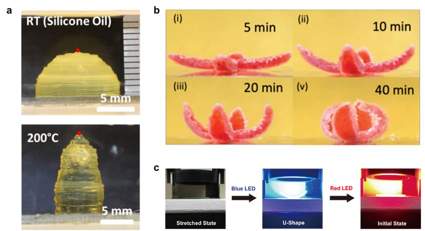
Appl. Sci. 2020, 10, 7254 2 of 17
Fused deposition modeling (FDM) is based on material extrusion, where thermoplastic materials
are melted and extruded through a nozzle. After extrusion, thermoplastic materials are solidified
again and piled up to form successive object layers. It is widely used in either low-cost 3D printers
or professional 3D printers, but it often results in low surface quality. In direct ink writing (DIW),
inks flow through a syringe nozzle because of their low viscosity with applied shear stress. After
printing, the structure maintains its 3D shape owing to the high viscosity of inks in the absence of
shear stress. Metal powders and ceramic powders can be 3D-printed via selective laser sintering (SLS).
The powder is sintered by a high-power laser and piled up layer-by-layer to form metal or ceramic
3D structures.
A few examples of 3D-printed components are shown in Figure 1: 3D-printed jet engine parts
Appl. Sci. 2020, 10, x FOR PEER REVIEW
[7]
3 of 18
(Figure 1a,b) and customized micro-lens (Figure 1c–e) [8–13].
Figure 1. (a) Jet engine fabricated by 3D printing application; (b) 3D-printed jet engine parts. From
Figure 2. (a)there
left figure, Jet engine
are fuelfabricated by 3D printing
nozzle, high-pressure application;
turbine nozzle, (b) 3D-printedturbine
high-pressure jet engine parts.
blade From
(Adapted
from
left [7]. Copyright
figure, (2017)
there are fuel Elsevier);
nozzle, (c) Tilted view
high-pressure of SEM
turbine image
nozzle, of the 3D-printed
high-pressure turbineoptical lens using
blade (Adapted
micro-stereolithography.
from Scale bar:(c)
[7]. Copyright (2017) Elsevier); 500 (d) Top
µm;view
Tilted viewimage
of SEM of SEM image
of the of the 3D-printed
3D-printed optical lensoptical
using
lens using micro-stereolithography.
micro-stereolithography. Scale
Scale bar: 500 μm;bar:
(d)500
Topµm; (e)ofMeasured
view SEM image surface
of theprofile of theoptical
3D-printed 3D-printed
lens
opticalmicro-stereolithography.
using lens (Adapted from [13]. Scale Copyright (2020)
bar: 500 μm;John
(e) Wiley & Sons).
Measured surface profile of the 3D-printed
optical lens (Adapted from [13]. Copyright (2020) John Wiley & Sons).
Four-dimensional (4D) printing adds active, responsive functions to 3D-printed structures. The 4D
printing concept was first
Four-dimensional (4D) introduced
printing adds byactive,
S. Tibbits et al. in
responsive 2013 [14,15].
functions They demonstrated
to 3D-printed structures. Thea
3D-printed
4D rod structure
printing concept was firstthat automatically
introduced transformed
by S. Tibbits into
et al. in 2013a [14,15].
predesigned 3D geometry awhen
They demonstrated 3D-
immersed in water. Four-dimensional printing is often realized by printing
printed rod structure that automatically transformed into a predesigned 3D geometry when smart materials, such as
liquid crystal
immersed elastomers
in water. (LCE) [16–18],printing
Four-dimensional hydrogels is [19–21], and shape
often realized memorysmart
by printing polymers (SMP)such
materials, [22–24].
as
Such structures
liquid can respond
crystal elastomers (LCE)to[16–18],
environmental
hydrogels stimuli.
[19–21],In and
this sense, 4D-printed
shape memory structures
polymers (SMP)are [22–
also
called
24]. Suchprogrammable
structures can matter, where
respond a response can be
to environmental programmed
stimuli. into materials
In this sense, 4D-printed via structures
structural and are
compositional
also design. In 4D
called programmable printing,
matter, where3D-printed
a response structures can be transformed
can be programmed in shape
into materials viainstructural
response
to external
and stimuli, such
compositional design.as heat
In 4D[25], water [26],
printing, light [27,28],
3D-printed and pH
structures [29].
can be transformed in shape in
Figure 3 shows several examples for 4D printing of smart
response to external stimuli, such as heat [25], water [26], light [27,28], and materials. Figure
pH 3a shows a 4D-printed
[29].
hemispherical shell, made
Figure 3 shows of LCE
several [30]. Owing
examples for 4Dtoprinting
the reversible arrangement
of smart materials.ofFigure
liquid crystal
3a shows molecules
a 4D-
at different temperatures, shape morphing occurs in a pre-determined way. Figure
printed hemispherical shell, made of LCE [30]. Owing to the reversible arrangement of liquid crystal 3b shows a gripper
made of hydrogels
molecules at different [31]. Due to different
temperatures, shapeswelling
morphing ratios between
occurs in aupper and lower way.
pre-determined layers,Figure
it can 3b
be
bent when
shows immersed
a gripper madeinofwater. Figure
hydrogels 3c shows
[31]. Due toadifferent
self-bending structure
swelling ratiosupon lightupper
between illumination
and lower[32].
layers, it can be bent when immersed in water. Figure 3c shows a self-bending structure upon light
illumination [32]. A bilayer structure was fabricated using multi-color SMP printing, where blue and
yellow SMP fibers were printed in a transparent elastomer matrix. Blue or red light can selectively
heat yellow or blue SMP fibers, and thus the 3D-printed multicolor composite can be deformed into
different shapes depending on light color. Four-dimensional printing could be useful for a wide range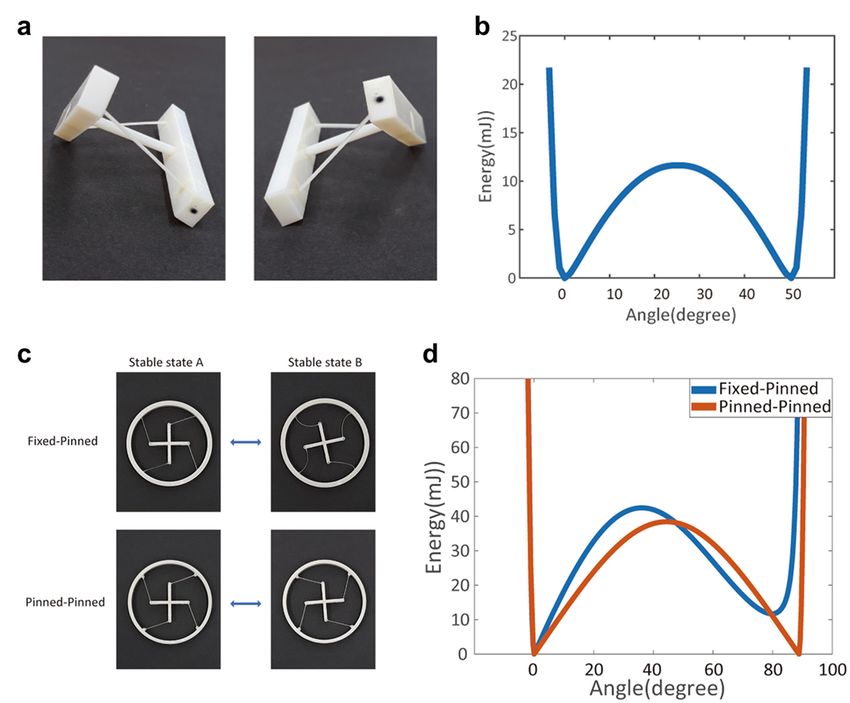
Fused deposition modeling (FDM) is based on material extrusion, where thermoplastic materials
are melted and extruded through a nozzle. After extrusion, thermoplastic materials are solidified
again and piled up to form successive object layers. It is widely used in either low-cost 3D printers or
professional 3D printers, but it often results in low surface quality. In direct ink writing (DIW), inks
Appl.
flowSci. 2020, 10,a 7254
      through                                                                                         3 of 17
                    syringe nozzle because of their low viscosity with applied shear stress. After printing,
the structure maintains its 3D shape owing to the high viscosity of inks in the absence of shear stress.
Metal powders and ceramic powders can be 3D-printed via selective laser sintering (SLS). The
A bilayer structure was fabricated using multi-color SMP printing, where blue and yellow SMP fibers
powder is sintered by a high-power laser and piled up layer-by-layer to form metal or ceramic 3D
were printed in a transparent elastomer matrix. Blue or red light can selectively heat yellow or blue
structures.
SMP fibers, and thus the 3D-printed multicolor composite can be deformed into different shapes
      A few examples of 3D-printed components are shown in Figure 2: 3D-printed jet engine parts
depending on light color. Four-dimensional printing could be useful for a wide range of potential
[7] (Figure 2a,b) and customized micro-lens (Figure 2c–e) [8–13].
applications, in actuators, switches, sensors, and deployable structures [33–35].

      Figure 2. Schematic of various 3D printing processes: stereolithography (SLA)/digital light projector
Appl. Sci. 2020,PolyJet
       (DLP),    10, x FOR
                        (orPEER REVIEW
                            Material jetting), direct laser writing (DLW), fused deposition modeling (FDM), direct4 of 18
      Figure 1. Schematic of various 3D printing processes: stereolithography (SLA)/digital light projector
      ink writing
      (DLP),      (DIW),
              PolyJet     selective laser
                      (or Material        sintering
                                    jetting), direct (SLS)
                                                     laser (Adapted  from [8].
                                                           writing (DLW),      Copyright
                                                                           fused         (2020)
                                                                                 deposition     De Gruyter).
                                                                                             modeling (FDM),
      direct ink writing (DIW), selective laser sintering (SLS) (Adapted from [8]. Copyright (2020) De
      Gruyter).

      Figure 3. (a) Three-dimensional printed hemispherical structure using liquid crystal elastomers (LCE).
     Figure 3. (a) Three-dimensional printed hemispherical structure using liquid crystal elastomers
      Due to the anisotropic arrangement of the LC molecules, the structure expands in the z-direction at
     (LCE).   Due to the anisotropic arrangement of the LC molecules, the structure expands in the z-
      200 ◦ C (Adapted from [30]. Copyright (2017) ACS Publications); (b) Transformation of initially flat
     direction at 200 °C (Adapted from [30]. Copyright (2017) ACS Publications); (b) Transformation of
      flower structure made by hydrogel bilayer blooming in the water. It takes 40 min to fully bloom
     initially flat flower structure made by hydrogel bilayer blooming in the water. It takes 40 min to fully
     (Adapted from [31]. Copyright (2019) John Wiley & Sons); (c) Transformation of initially flat stretched
     bloom (Adapted from [31]. Copyright (2019) John Wiley & Sons); (c) Transformation of initially flat
      structure that bends on blue LED illumination and recover to the initial state on red LED illumination
     stretched structure that bends on blue LED illumination and recover to the initial state on red LED
     (Adapted from [32]. Copyright (2020) Nature Publishing Group).
     illumination (Adapted from [32]. Copyright (2020) Nature Publishing Group).
     Usually, 3D-printed components are static structures with fixed shapes and functions. One possible
routeUsually,
      to realize3D-printed  componentsstructures
                 highly reconfigurable   are staticis structures with fixed
                                                      to use mechanical     shapes andIt allows
                                                                         multistability.  functions.   One
                                                                                                  multiple
possible route to realizeand
stable configurations,    highly reconfigurable
                             reversible         structures
                                        switching   betweenisthem
                                                               to use
                                                                    ismechanical multistability.
                                                                      possible under             It allows
                                                                                       proper mechanical
multiple stable configurations, and reversible switching between them is possible under proper
mechanical actions. Precisely controlled reconfiguration via multistability can bring many new
breakthroughs to 3D printing. In fact, multistability exists even in nature. The Venus flytrap is one
example (Figure 4a). The initially opened Venus flytrap leaf can abruptly snatch a worm by flipping
the curvature of its inner structure. This abrupt motion, also called snap-through, originates from
Appl. Sci. 2020, 10, 7254                                                                                                    4 of 17

 actions. Precisely controlled reconfiguration via multistability can bring many new breakthroughs to
 3D printing. In fact, multistability exists even in nature. The Venus flytrap is one example (Figure 4a).
The initially opened Venus flytrap leaf can abruptly snatch a worm by flipping the curvature of its
 inner structure. This abrupt motion, also called snap-through, originates from elastic bistability in the
 leaf [36].
       Figure 4b shows the elastic potential energy diagram of such a bistable structure. It has two stable
 configurations that are separated by an energy barrier. The slope in the energy diagram indicates
 the force applied at a given displacement. Enough force should be applied to overcome this barrier
 and transform into the other stable state. Once passing the hill of the barrier, the bistable structure is
 deformed into another configuration automatically. In this way, bistable structures can induce a rapid,
 large-magnitude movement and thus can be used to simplify actuation and motion control. They can
 also be used as mechanical switches, because they do not require energy to maintain a stable state.
       Bistability can be realized, for example, in strained bilayers and origami-based structures
(Figure 4c) [37,38]. More complicated multistable structures can also be realized by combining basic
 units together (Figure 4d) [39]. These multistable structures can be engineered with many different
 design parameters. More advanced functionalities and enhanced controllability can also be obtained
 in 4D printing by adopting active materials in multistable structures. This could be useful for various
Appl. Sci. 2020, 10, x FOR PEER REVIEW                                                               5 of 18
 smart actuators responding to the environmental stimuli.

      Figure 4. (a) Venus flytrap leaf in its closed and open states. Scale bar: 1 cm. (Adapted from [36].
     Figure   4. (a)(2020)
      Copyright       Venus   flytrap
                           John   Wileyleaf
                                          & in  its closed
                                             Sons);  (b) Anand    open of
                                                              example    states.  Scale bar:
                                                                            the energy         1 cm.of(Adapted
                                                                                          diagram       a bistablefrom  [36].
                                                                                                                    structure.
     Copyright    (2020)  John   Wiley   &  Sons);  (b) An   example   of  the  energy   diagram   of  a
      There are two stable states corresponding to local energy minima. Once stimuli overcome the energy bistable  structure.
     There  arethe
      barrier,   two   stablestructure
                    bistable  states corresponding      to local
                                         can snap-through         energy minima.
                                                              to another             Once
                                                                           stable state     stimuli overcome
                                                                                         automatically;           the energy
                                                                                                          (c) Origami-based
     barrier,  the bistable
      multistable             structure
                     structure.           cannumbers
                                  Different    snap-through      to states
                                                         of stable  another canstable
                                                                                 exist state  automatically;
                                                                                       depending    on design  (c)parameters
                                                                                                                    Origami-
     based   multistable
      (Adapted    from [37].structure.
                                 CopyrightDifferent
                                              (2015) numbers
                                                       AmericanofPhysical
                                                                      stable states    can(d)
                                                                               Society);     exist depending
                                                                                                Simulated         on of
                                                                                                            results   design
                                                                                                                        cubic
     parameters     (Adapted    from  [37].  Copyright    (2015)   American    Physical   Society); (d)  Simulated
      tessellation of a cuboctahedron unit cell. There are 4 stable states (Adapted from [39]. Copyright (2020)       results
     of cubicPublishing
      Nature    tessellationGroup).
                               of a cuboctahedron unit cell. There are 4 stable states (Adapted from [39].
     Copyright (2020) Nature Publishing Group).
      In this short review, we briefly discuss recent developments in 3D and 4D printing of mechanical
2.multistable
   3D Printing    of Mechanical
                structures.       Multistable
                             In Section 2, we Structures
                                                introduce three different approaches for 3D printing of
 multistable structures: strained layers, compliant mechanisms, and mechanical metamaterials.
2.1. Strained3,Layer
 In Section     we discuss 4D printing of multistable structures that could be applied to smart actuators.
 Lastly, in Section  4, we conclude
      One of the possible   ways towith    future
                                      realize     prospects.
                                              mechanical  multistability is the use of pre-strained layers
[40–43]. In 3D printing, a residual thermal stress often remains after printing and it can cause a
distortion of printed structures. Therefore, it is usually considered as a harmful effect and should be
minimized. However, this residual stress can also be utilized in a clever way to create multistable
structures. For example, Loukaides et al. fabricated bistable shell structures using selective laser
sintering of metal powders [44]. A residual stress remains after the sintering process, and bistable
shell structures can be formed (Figure 5a,b). The researchers printed cylindrical shells with varying
Appl. Sci. 2020, 10, 7254 5 of 17
2. 3D Printing of Mechanical Multistable Structures
2.1. Strained Layer
One of the possible ways to realize mechanical multistability is the use of pre-strained layers [40–43].
In 3D printing, a residual thermal stress often remains after printing and it can cause a distortion of
printed structures. Therefore, it is usually considered as a harmful effect and should be minimized.
However, this residual stress can also be utilized in a clever way to create multistable structures.
For example, Loukaides et al. fabricated bistable shell structures using selective laser sintering of metal
powders [44]. A residual stress remains after the sintering process, and bistable shell structures can be
formed (Figure 5a,b). The researchers printed cylindrical shells with varying curvatures. Figure 5a
shows as-printed shapes, while Figure 5b shows another stable state. They also found that, when the
pre-strain of the structure is too high, the structure becomes monostable (see the uppermost part in
Appl. Sci. 2020, 10, x FOR PEER REVIEW 6 of 18
Figure 5a,b). They also confirmed this behavior with analytic modeling.
5. (a) As-printed
Figure Figure 5. (a) As-printedshape
shapeof of
cylindrical
cylindrical shells (Radii5,6,7,8,9,10
shells (Radii 5,6,7,8,9,10
mmmmafterafter
removalremoval
from thefrom the build
build
plate); (b) Another
plate); stable
(b) Another state
stable of 3D-printed
state of 3D-printed cylindrical shells
cylindrical shells (Adapted
(Adapted fromfrom [44]. Copyright
[44]. Copyright (2019) (2019)
IOP Publishing); (c) Morphing
IOP Publishing); (c) Morphing behavior
behaviorofofaa 3D-printed bilayer
3D-printed bilayer structure.
structure. It remains
It remains flatTbelow
flat below g. Tg .
The initially
The initially flat structure
flat structure can can be activatedtotoaabistable
be activated bistable structure
structureabove Tg. It
above Tgcan
. Itmaintain an arbitrary
can maintain an arbitrary
shape due to the shape memory polymer characteristic; (d) Bistability can be expanded to
shape due to the shape memory polymer characteristic; (d) Bistability can be expanded to multistability
multistability with proper design: multistable chair structure and bistable Venus flytrap; (e) Bilayer
with proper design: multistable chair structure and bistable Venus flytrap; (e) Bilayer structure and
structure and gripper design utilizing iron/polylatic acid (PLA) filaments. The gripper is activated by
grippera design utilizingfrom
magnet (Adapted iron/polylatic acid
[45]. Copyright (PLA)
(2020) filaments. The gripper is activated by a magnet
Elsevier).
(Adapted from [45]. Copyright (2020) Elsevier).
Riley et al. reported a pre-strained bilayer using fused deposition modeling (FDM) [45]. FDM
Riley et al. reported
3D printing can createa pre-strained
pre-strain along bilayer usingdirection
the printing fused deposition
and this canmodeling
be used to (FDM) [45]. FDM 3D
encode proper
printingstrains in printed
can create structures.
pre-strain Figure
along the 5c shows adirection
printing schematicand of the
thisprinted
can be structure
used toand its behavior.
encode proper strains
Theystructures.
in printed printed a thin plate using
Figure polylatic
5c shows acid (PLA). The
a schematic lower
of the half of structure
printed the plate wasandprinted in the x They
its behavior.
direction, while the upper half of the plate was printed in the y direction. The printed structure
printed a thin plate using polylatic acid (PLA). The lower half of the plate was printed in the x direction,
remains flat after printing due to the high stiffness of PLA at room temperature. However, above the
while the upper
glass half of
transition the plate (T
temperature was printed in the y direction. The printed structure remains flat after
g), the strain is released in the printed PLA plate. Then, a saddle-like
printingbistable
due toshape
the high
can bestiffness
induced ofbyPLA at room in
the difference temperature. However,
the recovery direction abovethe
between theupper
glassandtransition
temperature (Tg ),This
lower parts. the bistable
strain is released
shape can bein the printed
flipped PLAtoplate.
from upward Then,and
downward a saddle-like bistable
vice versa. Above the shape
Tg, the PLAby
can be induced plate
thecan be deformed
difference to arbitrary
in the recovery shapes too. When
direction the structure
between is cooled
the upper down
and to room
lower parts. This
temperature, the temporary shape is fixed and does not show bistability. However, because of the
bistable shape can be flipped from upward to downward and vice versa. Above the Tg , the PLA plate
shape memory properties of PLA [25,46], when the structure is heated again above the Tg, it goes
can be deformed to arbitrary shapes too. When the structure is cooled down to room temperature,
back to its permanent, bistable shape. In this way, temperature can be used as a switch for bistability.
the temporary shape their
They expanded is fixed
ideaand does not structures
to multistable show bistability.
(Figure 5d), However,
and their because
3D-printed ofbilayers
the shapewerememory
also applied to a gripper that operates under mechanical or magnetic actuation (Figure 5e).
2.2. Compliant Mechanism
A compliant mechanism is another possible method to realize mechanical multistable structures
via 3D printing. A linear deformation of rigid materials can induce beam deflection in compliant
mechanisms, and this can be used to induce multistable structures [47–52]. Beam deflection can occur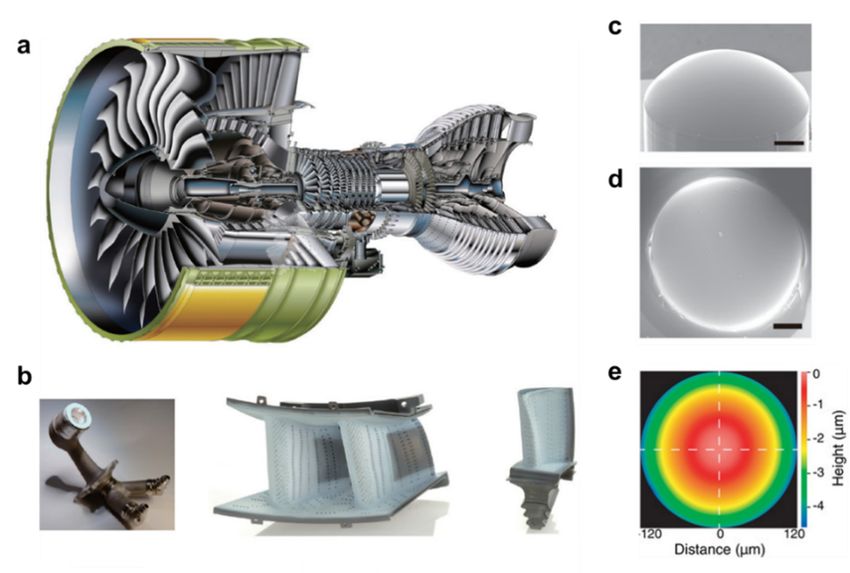
Appl. Sci. 2020, 10, 7254                                                                                                                6 of 17

properties of PLA [25,46], when the structure is heated again above the Tg , it goes back to its permanent,
bistable shape. In this way, temperature can be used as a switch for bistability. They expanded their
idea to multistable structures (Figure 5d), and their 3D-printed bilayers were also applied to a gripper
that operates under mechanical or magnetic actuation (Figure 5e).

2.2. Compliant Mechanism
      A compliant mechanism is another possible method to realize mechanical multistable structures
via 3D printing. A linear deformation of rigid materials can induce beam deflection in compliant
mechanisms, and this can be used to induce multistable structures [47–52]. Beam deflection can occur
in 3D-printed structures if a beam is thin enough; thus, 3D-printed compliant mechanisms can be used
to create various multistable structures. For example, Jeong et al. fabricated global bistable structures
via polyJet 3D printing [53]. By 3D printing ball and pin joints, they could realize twisting and rotating
bistable structures         without
           Appl. Sci. 2020, 10, x FOR PEER post   assembly. Figure 6a shows the two stable states of7the
                                             REVIEW                                                                      of 18 fabricated

twisting bistable structure. Because two stable states have the same shape, the overall energy diagram
           and rotating bistable structures without post assembly. Figure 6a shows the two stable states of the
is also symmetric          (Figure 6b). Using pin joints, they also fabricated rotational bistable structures
           fabricated twisting bistable structure. Because two stable states have the same shape, the overall
with two energy
            differentdiagramboundary          conditions:
                                  is also symmetric   (Figurefixed-pinned        andthey
                                                              6b). Using pin joints,   pinned-pinned        boundaries
                                                                                          also fabricated rotational bistable(Figure 6c).
The fixed-pinned boundary causes the beams in the stable state B to remain deformed. Because
           structures     with    two    different boundary    conditions:  fixed-pinned   and  pinned-pinned    boundaries
           (Figurebeams
the deformed           6c). Theretain
                                  fixed-pinned
                                           higherboundary
                                                    elastic causes
                                                              energy,thethe
                                                                          beams  in the energy
                                                                              overall   stable state B to remain
                                                                                                  diagram         deformed.
                                                                                                              becomes       asymmetric,
           Because the deformed beams retain higher elastic energy, the overall energy diagram becomes
as shownasymmetric,
            in Figure 6d          (blue    line).  On    the other  hand,     the  pinned-pinned       boundary
                             as shown in Figure 6d (blue line). On the other hand, the pinned-pinned boundary
                                                                                                                     allows     the stable
states A and
           allowsB to thehave
                           stableidentical      shapes.
                                     states A and          Therefore,
                                                    B to have   identical the  overall
                                                                           shapes.      energy
                                                                                   Therefore,  thediagram     remains
                                                                                                    overall energy        symmetric in
                                                                                                                    diagram
this case, remains
           as shown         in Figure
                        symmetric           6dcase,
                                       in this  (redas line).
                                                        shown in Figure 6d (red line).

      Figure 6. Figure
                  (a) Two6. (a) Two stable
                             stable    statesstates
                                                of aof3D-printed
                                                       a 3D-printed twisting
                                                                       twisting bistable structure
                                                                                   bistable         with ball
                                                                                              structure       joints.
                                                                                                           with   ballThe  black The black
                                                                                                                        joints.
      small dotsmall   dot is marked for eye tracing; (b) Simulated energy diagram of the twisting bistable structure.
                  is marked      for eye tracing; (b) Simulated energy diagram of the twisting bistable structure.
                 Due to the same shape of beams between two stable states, the energy diagram is also symmetric; (c)
      Due to the    same shape of beams between two stable states, the energy diagram is also symmetric;
                 Two stable states of a 3D-printed rotational bistable structure with pin joints. When the inner cross is
      (c) Two stable   states
                 rotated         of awhile
                         clockwise     3D-printed
                                             the outer rotational    bistable
                                                       ring is held fixed,      structure
                                                                           the structure canwith    pin from
                                                                                              transform  joints.  When
                                                                                                               stable state the
                                                                                                                            A toinner cross
      is rotated another
                 clockwisestablewhile    the
                                  state B; (d)outer
                                               Energyring  is held
                                                       diagram        fixed,
                                                                 of the       the structure
                                                                        rotational              can transform
                                                                                   bistable structure             from
                                                                                                      with different      stable state A to
                                                                                                                      boundary
                 conditions
      another stable   state(Adapted      from [53].diagram
                                B; (d) Energy        Copyrightof (2019)  Nature Publishing
                                                                   the rotational            Group).
                                                                                      bistable    structure with different boundary
      conditionsTherefore,
                   (Adapted       from    [53].  Copyright      (2019)   Nature     Publishing
                               it is possible to adjust the overall energy diagram of the          Group).
                                                                                                      bistable structure and this
             can be used to tailor the mechanical response of printed structures. By adjusting the structural
             parameters or printing materials, it is possible to control the barrier height (i.e., the threshold energy
             for a shape change), the slope of the barrier (the force required for a shape change), and the amount
             of initial displacement to trigger a shape change. By connecting bistable structures, it is also possible
             to create multistable components. Therefore, this work demonstrates that 3D-printed multistable
             structures can be employed to realize highly controlled reconfiguration.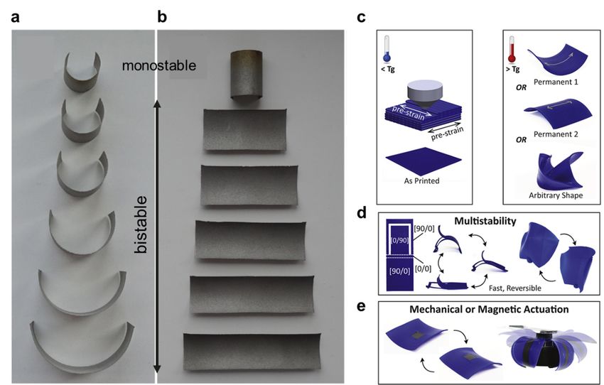
Appl. Sci. 2020, 10, 7254                                                                                             7 of 17

       Therefore, it is possible to adjust the overall energy diagram of the bistable structure and this can
be used to tailor the mechanical response of printed structures. By adjusting the structural parameters
or printing materials, it is possible to control the barrier height (i.e., the threshold energy for a shape
change), the slope of the barrier (the force required for a shape change), and the amount of initial
displacement to trigger a shape change. By connecting bistable structures, it is also possible to create
multistable components. Therefore, this work demonstrates that 3D-printed multistable structures can
Appl. Sci. 2020, 10, x FOR PEER REVIEW                                                                8 of 18
be employed to realize highly controlled reconfiguration.
2.3.
 2.3. Mechanical
      MechanicalMetamaterial
                    Metamaterial
      A   bistableelement
       A bistable    element cancan    be used
                                  be used          as structure
                                            as a unit  a unit structure
                                                                to constructtomultistable
                                                                                construct mechanical
                                                                                            multistablemetamaterials.
                                                                                                           mechanical
metamaterials.
 Properly designed mechanical metamaterials can show unusual mechanical properties suchmechanical
                     Properly     designed      mechanical    metamaterials       can  show    unusual      as negative
properties    such   as  negative    Poisson’s    ratio, negative   stiffness,  energy   trapping,
 Poisson’s ratio, negative stiffness, energy trapping, etc. [54–60]. For example, constrained tiltedetc.  [54–60].  For
example,     constrained
 elastic beams    can be used tilted  elastic beams
                                   to construct           can be
                                                   multistable      used to metamaterials
                                                                mechanical      construct multistable      mechanical
                                                                                                (Figure 7a–f).    While
metamaterials      (Figure  7a–f).   While   an  axially compressed     elastic beam  only  has
 an axially compressed elastic beam only has a single stable state (Figure 7a), a constrained    a single  stable tilted
                                                                                                                   state
(Figure
 beam with7a), fixed
                a constrained
                      and rollertilted   beamconditions
                                   boundary      with fixed can
                                                             andhold
                                                                   roller  boundary
                                                                        another        conditions
                                                                                  deformed   stablecan   hold
                                                                                                     state      another
                                                                                                            (Figure  7b).
deformed     stable   state (Figure    7b). The   force-displacement     curve   in Figure  7b shows    that
The force-displacement curve in Figure 7b shows that it can be used as a bistable element. The difference     it can be
used   as a bistable element. The difference between Ein and Eout in the force-displacement curve is the
 between Ein and Eout in the force-displacement curve is the amount of trapped energy in this bistable
amount    of trapped energy in this bistable element (Figure 7b).
 element (Figure 7b).

      Figure 7. (a) An axially compressed elastic beam does not show bistability. It fully recovers to its
     Figure 7. (a) An axially compressed elastic beam does not show bistability. It fully recovers to its initial
      initial state when unloaded; (b) An constrained tilted elastic beam can show bistability and energy
     state when unloaded; (b) An constrained tilted elastic beam can show bistability and energy trapping
      trapping (Ein − Eout > 0). The deformed tilted elastic beam can recover to its initial state when enough
     (Ein − Eout > 0). The deformed tilted elastic beam can recover to its initial state when enough energy is
      energy is applied; (c) Compression test of 3D-printed multistable mechanical metamaterials. The
     applied; (c) Compression test of 3D-printed multistable mechanical metamaterials. The sequentially
      sequentially deformed structure maintains a deformed state even after unloading; (d) Measured force
     deformed structure maintains a deformed state even after unloading; (d) Measured force and
      and displacement graph. The overall deformation tendency is independent of loading conditions;
     displacement graph. The overall deformation tendency is independent of loading conditions; (e)
      (e) Demonstration of multistable mechanical metamaterials as an energy absorber. A raw egg mounted
     Demonstration
      on the multistableof multistable
                             mechanicalmechanical    metamaterials
                                          metamaterial     survived as an energy
                                                                     when          absorber.
                                                                             dropped   from aA height
                                                                                               raw egg   ofmounted
                                                                                                            12.5 cm;
     on
      (f) Measured acceleration-time curve of three different cases. The control sample was taped so cm;
          the multistable   mechanical   metamaterial    survived when   dropped    from  a height  of  12.5  that (f)
                                                                                                                    all
     Measured     acceleration-time  curve  of  three different cases. The  control sample  was  taped
      beams were intentionally collapsed before the drop test. The snap-through sample shows snap-through so that  all
     beams
      behaviorwere
                 but intentionally  collapsed
                     not energy trapping.       before the
                                           Multistable      drop test.
                                                         mechanical     The snap-through
                                                                     metamaterials          sample shows
                                                                                     show a significant        snap-
                                                                                                         decrease   in
     through    behavior   but not energy trapping.   Multistable  mechanical   metamaterials  show    a significant
      acceleration (Adapted from [57]. Copyright (2015) John Wiley & Sons); (g) Examples of 3D multistable
     decrease
      mechanicalin acceleration
                    metamaterials(Adapted
                                    (Adaptedfrom
                                               from[57]. Copyright
                                                     [60]. Copyright(2015)
                                                                      (2016)John
                                                                              JohnWiley
                                                                                   Wiley&&Sons);
                                                                                            Sons).(g) Examples of
     3D multistable mechanical metamaterials (Adapted from [60]. Copyright (2016) John Wiley & Sons).

      Tilted beam bistable structures can be 3D-printed and have been used for multistable mechanical
metamaterials. Shan et al. fabricated multistable energy trapping structures via direct ink writing
[57]. They printed a 4 × 4 bistable structure using polydimethylsiloxane (PDMS), as shown in Figure
7c. When the fabricated multistable structure is uniaxially compressed, it undergoes snap-through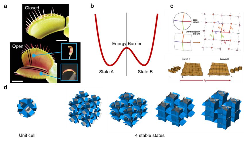
Appl. Sci. 2020, 10, 7254                                                                           8 of 17

     Tilted beam bistable structures can be 3D-printed and have been used for multistable mechanical
metamaterials. Shan et al. fabricated multistable energy trapping structures via direct ink writing [57].
They printed a 4 × 4 bistable structure using polydimethylsiloxane (PDMS), as shown in Figure 7c.
When the fabricated multistable structure is uniaxially compressed, it undergoes snap-through four
times because of four bistable layers along the compression direction. Figure 7d shows the measured
force-displacement curve; four peaks correspond to the beginning of the snap-through. All peaks have
the same magnitude because the structure consists of identical bistable layers. They also demonstrated
that multistable metamaterials can be used as an energy absorber. As a proof-of-concept, they conducted
a free-fall measurement of eggs. It is also compared to a control sample (taped) that does not show
multistable behavior. An egg mounted on the multistable structure was unharmed and survived when
it was dropped from the height (h) of 12.5 cm (Figure 7e). However, an egg on the control sample was
broken because the control sample does not have the energy-absorbing capability. Figure 7f compares
the acceleration-time graph for three cases: control sample, snap-through-only sample, and multistable
sample. The control sample does not have an energy absorbing function and thus shows a high
acceleration peak in a shortest time (blue curve). The snap-through-only sample shows a snap-through
but without energy trapping. It still shows a reduced peak acceleration (green curve) compared to
the control sample, due to the energy absorbing from the viscoelasticity of the material (not from the
elastic energy trapping). The multistable sample shows a remarkable reduction in the peak amplitude
because of the elastic energy trapping in mechanical metamaterials (red). Therefore, it could protect an
egg during freefall.
     Constrained tilted beams have also been used to control a snapping sequence in multistable
metamaterials by 3D-printing imperfect unit cells [58] or adopting different materials on each layer [59].
Beam-based multistable metamaterials have been extended to 3D geometries too (Figure 7g) [60].
These studies demonstrate design flexibility available for multistable mechanical metamaterials.

3. 4D Printing of Multistable Structures

3.1. Heat-Responsive Structures
     Four-dimensional printing can be implemented by printing smart materials. For example, SMPs
can be employed as an active material in 4D printing. SMPs are smart materials that memorize a
permanent shape. SMPs soften above the Tg and allow reshaping. This temporary shape can be fixed
by cooling back to room temperature (also called thermo-mechanical programming), where SMPs
exhibit significant stiffness. An SMP can be deformed into multiple, arbitrary temporary shapes and
return to a permanent shape again upon a proper external stimulus (heat or light). Because SMPs can
be readily printed in conventional 3D printers, SMPs have been widely considered for 4D printing
research. By adopting SMPs in multistable structures, more advanced functionalities and enhanced
controllability can be realized. Multistability can also help in increasing the load bearing capacity and
the magnitude of actuation force.
     For example, Tian Chen et al. devised a 3D-printed programmable actuator by combining a
bistable structure with SMPs [35,61]. Figure 8a shows a schematic of their bistable structure (von Mises
truss). Trusses are made of rigid materials, while beams and joints are based on compliant mechanisms.
It possesses two stable states (retracted and extended states) which can be combined together to form
a 3D geometry (Figure 8b). This bistable structure can be actuated by SMP strips. These strips can
be deformed to a contracted shape above Tg . When cooled back to room temperature, SMP strips
maintain the deformed shape (programmed state) (Figure 8c). Due to the SMP recovery, the deformed
SMP strips return to the original state again above the Tg (activation). Figure 8d shows the bistable
energy and force diagram. Once the SMP recovery force overcomes the energy barrier of the bistable
structure, the unit actuator can snap-through to another stable state automatically. The recovery force
can overcome the energy barrier by adjusting the thickness of SMP strips (Figure 8e).
Appl. Sci. 2020, 10, 7254 9 of 17
Appl. Sci. 2020, 10, x FOR PEER REVIEW 10 of 18
Figure 8. (a) Schematic of a 3D-printed von Mises bistable structure. The rigid bracket provides
Figure 8. rigidity,
structural (a) Schematic
while theof aflexible
3D-printed von Mises
joints provide bistable structure.
a rotational motion of The rigid (b)
the truss; bracket provides
A 3D-printed
structural rigidity, while the flexible joints provide a rotational motion of the truss; (b)
bistable flat structure can be reconfigured to a 3D geometry via bistability (Adapted from [35]. Copyright A 3D-printed
bistable
(2017) flat structure
Nature Publishing can be reconfigured
Group); to a 3D
(c) Programming andgeometry
activation via
of bistability
SMP strips;(Adapted from
(d) Bistable [35].
energy
Copyright
and (2017) with
force diagram Nature
twoPublishing
stable statesGroup);
I and III;(c)
(e)Programming
Finite element and activation of SMP
(FE) simulation SMPstrips
strips; (d)
with
Bistablethicknesses;
varying energy and(f) force diagram
Schematic ofwith two stableswimming
an untethered states I and III; (e)
robot thatFinite element
enables (FE) simulation
a fin stroke in water;
of Images
(g) SMP strips with
of the varyingrobot
swimming thicknesses;
in warm(f) water (T > Tgof
Schematic anthe
) at untethered swimming
different phases robot that
of activation enables
(Adapted
a fin [61].
from stroke in water; (2018)
Copyright (g) Images of the
National swimming
Academy robot in warm water (T > Tg) at the different phases
of Sciences).
of activation (Adapted from [61]. Copyright (2018) National Academy of Sciences).
They also developed an autonomous actuator to realize soft, untethered robots for navigation and
deliveryThey[61].
alsoFigure 8f shows
developed a schematic ofactuator
an autonomous the proposed
to realizeactuator. By attaching
soft, untethered fins to
robots forthe bistable
navigation
structure, it can be actuated in water by a fin stroke. The large displacement
and delivery [61]. Figure 8f shows a schematic of the proposed actuator. By attaching fins to the of the bistable structure
and the amplification
bistable structure, it canof the
be actuation
actuated inforce
waterhelps
by the
a finrobot to swim
stroke. in water.
The large The programmed
displacement SMP
of the bistable
actuator
structurecan andreturn
the to its original state
amplification above
of the Tg . When
actuation forcethehelps
SMP strip overcomes
the robot the energy
to swim in water.barrier
The
of the bistableSMP
programmed structure,
actuator thecan
robot can to
return stroke its fins.
its original Figure
state above8gTshows
g. Whenimages
the SMP of strip
the swimming
overcomes
robots.
the energyThe robot
barriercanof show sequential
the bistable propulsion
structure, or directional
the robot can strokemotion byFigure
its fins. adjusting the thickness
8g shows imagesof of
SMP strips.
the swimming robots. The robot can show sequential propulsion or directional motion by adjusting
Jeong et al.
the thickness ofused
SMPastrips.
rotational bistable structure (Figure 6) to fabricate a smart thermal actuator [62].
Multistable
Jeong structures
et al. usedcan simplify actuation
a rotational and motion
bistable structure control
(Figure 6) without complicated
to fabricate control systems.
a smart thermal actuator
Figure 9a shows the
[62]. Multistable design schematic
structures of the
can simplify structure.
actuation and They employ
motion two without
control differentcomplicated
digital SMPscontrol
(rigid
and rubbery
systems. ones)9atoshows
Figure enablethelarge-angle, thermal actuation
design schematic in a controlled
of the structure. manner.two
They employ Thedifferent
rigid beam has
digital
aSMPs
fixed-pinned
(rigid and boundary,
rubbery while
ones) the rubbery
to enable one has a fixed-fixed
large-angle, boundary.
thermal actuation in aTwo rigid beams
controlled manner.define
The
the overall
rigid beambistability, while the rubbery
has a fixed-pinned boundary, beams act the
while as arubbery
control knob.
one has Those multistable
a fixed-fixed structuresTwo
boundary. do
not require
rigid beams heating
defineinthethe overall
programming stagewhile
bistability, and thisthesignificantly
rubbery beamssimplifies
act asthe actuation
a control procedure
knob. Those
(Figure 9b,c). structures do not require heating in the programming stage and this significantly
multistable
simplifies the actuation procedure (Figure 9b,c).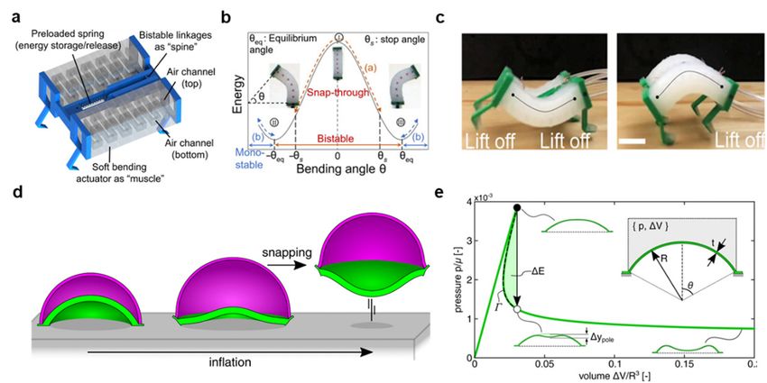
Appl.Sci.
Appl.  Sci.2020,  10,x7254
            2020,10,   FOR PEER REVIEW                                                                              10ofof18
                                                                                                                   11      17

      Figure9.9.(a)(a)
     Figure            Schematic
                    Schematic of aofrotational
                                      a rotational bistable
                                               bistable     structure
                                                        structure      thatbe
                                                                  that can  can  be activated
                                                                              activated        bysimilar
                                                                                        by heat:   heat: similar  to
                                                                                                          to Figure
      Figure 6c but two fixed-pinned beams were replaced by fixed-fixed rubbery beams; (b) Operating
     6c but two fixed-pinned beams were replaced by fixed-fixed rubbery beams; (b) Operating procedure
      procedure of the fabricated thermal actuator. It is possible to program the structure at room temperature.
     of the fabricated thermal actuator. It is possible to program the structure at room temperature. The
      The rotated structure (stable state B) at room temperature returns to its original stable state A at
     rotated structure (stable state B) at room temperature returns to its original stable state A at 75 °C; (c)
      75 ◦ C; (c) Images of the thermal actuator in 75 ◦ C water. It returns to the initial stable state in 0.8 s;
     Images of the thermal actuator in 75 °C water. It returns to the initial stable state in 0.8 s; (d) Activation
      (d) Activation time of the thermal actuator for different rubbery beam thicknesses; (e) Comparison of
     time of the thermal actuator for different rubbery beam thicknesses; (e) Comparison of the shape
      the shape memory force and barrier force. Thermal actuation occurs when the shape memory force is
     memory force and barrier force. Thermal actuation occurs when the shape memory force is larger
      larger than the barrier force (Adapted from [62]. Copyright (2019) John Wiley & Sons).
     than the barrier force (Adapted from [62]. Copyright (2019) John Wiley & Sons).
       In their design, by adjusting the thickness of SMP beams, they could control a balance between
      In theirbarrier
 the energy      design,  byshape-memory
                        and  adjusting the thickness
                                               force, andofthis
                                                             SMP    beams,
                                                                enabled      they could
                                                                          controlled      control
                                                                                      thermal        a balance
                                                                                                 actuation.       between
                                                                                                               They   could
the  energy    barrier   and shape-memory        force,  and   this  enabled   controlled   thermal
 also control the activation time for thermal actuation; as the thickness of rubber SMP increases, the  actuation.   They
could   also control
 activation            the activation
               time decreases           time
                                  (Figure    for thermal
                                            9d).            actuation;
                                                  The researchers        as the thickness
                                                                       conducted            of rubber
                                                                                    a detailed           SMPusing
                                                                                                  analysis      increases,
                                                                                                                      finite
the  activation   time   decreases  (Figure   9d).  The researchers     conducted   a detailed
 element simulations and shape memory force measurements (Figure 9e). They also extended their    analysis   using   finite
element
 bistable simulations
            structures toand    shape memory
                            quadristable           force measurements
                                            ones. Thus,                      (Figure 9e).
                                                           4D-printed multistable          They also
                                                                                      structures     couldextended
                                                                                                             be usefultheir
                                                                                                                         for
bistable  structures    to quadristable    ones.  Thus,  4D-printed     multistable
 various smart and programmable actuators responding to the environmental stimuli.   structures     could   be useful   for
various smart and programmable actuators responding to the environmental stimuli.
 3.2. Solvent-Responsive Structures
3.2. Solvent-Responsive Structures
       Jiang et al. demonstrated logic operation using stimuli-responsive bistable structures [63].
 The Jiang
      bistableet al. demonstrated
                 structures           logic operation
                             were fabricated     via the using
                                                          direct stimuli-responsive
                                                                 ink writing (DIW) of   bistable   structures
                                                                                           glass fiber           [63]. The
                                                                                                         (GF) embedded
bistable   structures    were  fabricated   via  the  direct  ink  writing   (DIW)   of  glass  fiber
 polydimethylsiloxane (PDMS). The GF in a PDMS network can be aligned along the extrusion direction.   (GF)   embedded
polydimethylsiloxane
 PDMS can absorb non-polar  (PDMS).     The GF
                                   solvents  suchinasatoluene.
                                                         PDMS Aligned
                                                                  networkGFs  canprevent
                                                                                  be aligned
                                                                                           PDMSalongfrom the    extrusion
                                                                                                           swelling   along
direction.
 the aligned PDMS     can so
                direction, absorb   non-polar swelling
                              that anisotropic   solvents can
                                                            suchbeas  toluene.The
                                                                    achieved.    Aligned   GFs of
                                                                                    schematic    prevent    PDMS
                                                                                                    the bistable     from
                                                                                                                   element
swelling
 is shownalong      the aligned
             in Figure   10a. Thedirection,   so that anisotropic
                                    bistable structure    consists ofswelling
                                                                       two beamscan with
                                                                                     be achieved.
                                                                                           fixed and  The   schematic
                                                                                                         roller  boundaryof
the bistable element is shown in Figure 10a. The bistable structure consists of two beams with fixed
Appl. Sci. 2020, 10, 7254 11 of 17
Appl. Sci. 2020, 10, x FOR PEER REVIEW 12 of 18
conditions
and(same as Figureconditions
roller boundary 7c). In this configuration,
(same theInstructure
as Figure 7c). can havethe
this configuration, monostability
structure canor bistability
have
monostability
upon geometrical or bistabilityThey
parameters. upon kept
geometrical parameters.
the tilted 45◦ ,kept
angle asThey the they
while tiltedchanged
angle as 45°,
the while
slenderness
they changed the slenderness ratio (w/L). There exists a certain slenderness ratio that divides
ratio (w/L). There exists a certain slenderness ratio that divides monostability and bistability, which is
monostability and bistability, which is called a bifurcation point. Figure 10b shows the energy
called adiagram
bifurcation point. Figure 10b shows the energy diagram of the monostable and bistable
of the monostable and bistable structures. The energy of the monostable structure
structures. The energy of the monostable
monotonically increases, while the energy structure
of themonotonically
bistable structureincreases,
has a local while the energy
minimum that of the
bistablecorresponds
structure has to a asecond
local stable
minimum that corresponds
state. Figure 10c shows theto a second
geometric stable
phase state.together
diagram Figurewith 10c shows
the image
the geometric of printed
phase diagramstructures. Due to
together the the
with anisotropic
image swelling, the structures.
of printed slenderness ratio
Dueoftothethe
PDMS-
anisotropic
GFthe
swelling, bistable structureratio
slenderness can be
ofincreased when itbistable
the PDMS-GF is immersed in toluene.
structure can Therefore,
be increased bistability
whencanit isturn
immersed
into monostability (see the blue curve). At the transition point, the transition speed is found to be
in toluene. Therefore, bistability can turn into monostability (see the blue curve). At the transition
very fast (less than 0.01 s).
point, the transition speed is found to be very fast (less than 0.01 s).
Figure 10.
Figure(a)10.
Schematic andand
(a) Schematic image
image ofofa abistable structure;(b)(b)
bistable structure; Energy-displacement
Energy-displacement curve
curve of the of the
bistablebistable
structure (I) and
structure (I) the
and monostable
the monostablestructure (III).The
structure (III). Theinset
inset images
images are configuration
are configuration of beamsof beams
at each at
stable state; state;
each stable (c) The initially
(c) The bistable
initially bistablestructure (I)can
structure (I) cantransform
transform intointo a monostable
a monostable structure
structure
(III) due(III) due to anisotropic
to anisotropic beambeam swelling.
swelling. Thereisisaa transition
There transition atat
the bifurcation
the pointpoint
bifurcation (II). Representative
(II). Representative
images images
are also areshown
also shown at bottom
at the the bottom forforthe
thebistable
bistable state
state(red),
(red),thethe
bifurcation pointpoint
bifurcation when when
actuation
actuation
occurs (green), and the monostable state (black); (d) Logic gates fabricated by combining glass fiber
occurs (green), and the monostable state (black); (d) Logic gates fabricated by combining glass fiber
embedded polydimethylsiloxane (PDMS-GF) (activated by toluene) and hydgrogel-nanofibrillated
embedded polydimethylsiloxane
cellulose (PDMS-GF)
(NFC) (activated by water) (activated
bistable structures by toluene)
(Adapted and
from [63]. hydgrogel-nanofibrillated
Copyright (2019) Nature
cellulosePublishing
(NFC) (activated
Group). by water) bistable structures (Adapted from [63]. Copyright (2019) Nature
Publishing Group).
They also fabricated a bistable structure using hydrogels embedded with nanofibrillated
cellulose
They (NFC). The aNFC
also fabricated filler prevents
bistable structurehydrogels from isotropic
using hydrogels swelling in
embedded water.
with The researchers
nanofibrillated cellulose
fabricated
(NFC). The NFC afiller
proof-of-concept module for
prevents hydrogels logicisotropic
from operationswelling
by selectively activating
in water. Thebistable elements
researchers fabricated
in a polar or non-polar solvent (Figure 10d). Combining the PDMS-GF (activated by toluene) and
a proof-of-concept module for logic operation by selectively activating bistable elements in a polar or
non-polar solvent (Figure 10d). Combining the PDMS-GF (activated by toluene) and hydrogel-NFC
(activated by water) bistable elements together, they could demonstrate AND, OR, and NAND logic
gates. The AND gate consists of a hydrogel valve and a PDMS-GF bistable unit (both water and toluene
required). The OR gate consists of a combined hydrogel-NFC and PDMS-GF bistable unit (either water
or toluene required). The NAND gate is constructed by connecting two input bistable units to oneAppl. Sci. 2020, 10, x FOR PEER REVIEW 13 of 18
Appl. Sci. 2020, 10, 7254(activated by water) bistable elements together, they could demonstrate AND, OR,12 of 17
hydrogel-NFC
and NAND logic gates. The AND gate consists of a hydrogel valve and a PDMS-GF bistable unit
(both water and toluene required). The OR gate consists of a combined hydrogel-NFC and PDMS-GF
output unit. unit
bistable The (either
connected
waterinput and output
or toluene parts
required). canNAND
The be activated by applyingbytoluene
gate is constructed to both
connecting twoinput
units.input
In this way, an initially opened output unit can be closed. They could also control
bistable units to one output unit. The connected input and output parts can be activated by the actuation
time applying
by adjusting theto
toluene slenderness ratio.In
both input units. This
thisactuator is scale-independent,
way, an initially and can
opened output unit thusbeitclosed.
can beThey
modified
properly
couldfor other
also applications
control including
the actuation time bysoftadjusting
robotics,the
biomedical
slendernessdevices, and deployable
ratio. This structures.
actuator is scale-
independent,
Other responsive and thus it can be
materials canmodified
also be properly
used forfor other applications
multistable including
structures. soft robotics,
For example, Figure 5e
biomedical devices, and deployable structures.
shows a bistable bilayer structure that was 3D-printed with iron/PLA filaments. The gripper action
Other responsive
can be triggered materials
by an external can also field
magnetic be used for multistable
above the Tg . A structures.
variety of For example,
smart Figure 5e
and programmable
shows a bistable bilayer structure that was 3D-printed with iron/PLA filaments. The gripper action
actuators can be realized via 4D-printed multistable structures, in response to various environmental
can be triggered by an external magnetic field above the Tg. A variety of smart and programmable
stimuli, such as heat, light, moisture, pH level, and electric/magnetic fields.
actuators can be realized via 4D-printed multistable structures, in response to various environmental
stimuli, such as heat, light, moisture, pH level, and electric/magnetic fields.
4. Conclusions and Future Prospects
4. Conclusions
Lastly, and Future
in this section, weProspects
introduce a few more recent works that utilized multistable structures
for actuation and
Lastly, reconfiguration.
in this Although
section, we introduce a fewthey
moreare not works
recent yet fully
that3D-printed, these works
utilized multistable provide
structures
interesting perspectives on multistability. As multi-material 3D-printing technologies
for actuation and reconfiguration. Although they are not yet fully 3D-printed, these works provide are developing
interesting
rapidly, perspectives
we expect on multistability.
that similar As multi-material
structures could also be realized3D-printing
via 3Dtechnologies
printing in are
thedeveloping
near future.
rapidly,
Tang etwe al.expect that similar structures
[64] developed a bistablecould
spinealso be realized for
mechanism via 3D printing inrobots
soft-legged the near(Figure
future. 11a–c).
Tang et al. [64] developed a bistable spine mechanism for soft-legged
They demonstrated high-speed yet energy-efficient spine flexion and extension with insightsrobots (Figure 11a–c). They from
demonstrated high-speed yet energy-efficient spine flexion and extension with insights from
quadrupedal mammals. High-speed locomotion requires the rapid storage and release of large
quadrupedal mammals. High-speed locomotion requires the rapid storage and release of large
mechanical energy as well as high force output. However, most soft robots have slow response time
mechanical energy as well as high force output. However, most soft robots have slow response time
and low energy exertion due to material softness and structural compliance. Motivated by galloping
and low energy exertion due to material softness and structural compliance. Motivated by galloping
cheetahs, a bistable
cheetahs, hybrid
a bistable softsoft
hybrid bending
bendingactuator
actuatorwas
wasproposed
proposedtotoovercome
overcomethisthislimitation.
limitation. It
It was
was built
by joining 3D-printed, spring-based bistable linkages (“spine”) to soft pneumatic
built by joining 3D-printed, spring-based bistable linkages (“spine”) to soft pneumatic bending bending actuators
(“muscles”)
actuators(Figure 11a,b).
(“muscles”) They11a,b).
(Figure demonstrated a high-speed
They demonstrated soft crawler
a high-speed (Figure(Figure
soft crawler 11c) using a bistable
11c) using
spinea mechanism,
bistable spinewhich
mechanism,
is overwhich is over
2.5 times 2.5 and
faster timesstill
faster and still
requires lessrequires less input
input energy for energy
operationfor than
operation than high energy density
high energy density dielectric crawlers. dielectric crawlers.
Figure 11. (a)
Figure 11. Schematic
(a) Schematicof of
a bistable
a bistablehybrid
hybrid soft bendingactuator
soft bending actuator (BH-SBA).
(BH-SBA). It consists
It consists of twoof soft
two soft
air-bending actuators,
air-bending 3D-printed
actuators, 3D-printedbistable linkages,
bistable andand
linkages, a preloaded
a preloaded spring that
spring stores
that potential
stores potentialenergy
and releases
energy andwhen the air
releases channel
when is channel
the air pressurized; (b) Energy
is pressurized; (b)diagram of the bistable
Energy diagram actuator.
of the bistable The axially
actuator.
The axially spring
pre-tensioned pre-tensioned
makesspring
maximum makes energy
maximum at energy
the zeroat the zero bending
bending angle. angle.
As the Asspring
the spring
releases
releaseswith
the energy the energy with the
bending, bending,
whole theenergy
whole energy decreases
decreases and finally
and finally reaches
reaches thethe energyminima
energy minima (θeq );
(θeq); (c) Fabricated
(c) Fabricated bio-inspired
bio-inspired crawler withcrawler
the with
spinethe spine actuation.
actuation. The spineThebends
spine upward
bends upward
to storetoenergy
store and
energy and downward to release energy (Adapted from [64]. Copyright (2020) AAAS); (d) Fabricated
downward to release energy (Adapted from [64]. Copyright (2020) AAAS); (d) Fabricated soft actuator
that can jump when the inner spherical cap flips downward during inflation; (e) Pressure-volume curve
of the soft actuator. Isochoric snapping can occur and the inner spherical cap flips downward. During
the flipping, the volume of cavity is maintained but the pressure drops. ∆E is the amount of energy
releasing (Adapted from [65]. Copyright (2020) AAAS).You can also read