TORQBEE OPERATING INSTRUCTIONS - HS-TECHNIK GMBH
←
→
Page content transcription
If your browser does not render page correctly, please read the page content below
OPERATING INSTRUCTIONS
                     TorqBee®
                       - Original operating instructions -

                                                Battery tightening tool
NOTE                                            TBPxx-xxx / TBAxx-xxx / TBSxx-xxx
                                                Issue date:                March 2021
In case of doubt, the original German version   Tool Firmware:             from 2.2.6.0
of the operating instructions applies.          HST-Tool-Manager:          from 2.0.6.0
Table of contents

             4    1 Operating principles
      PAGE

                  1.1    Scope of delivery                                         4
                  1.2    General information                                       4
                  1.3    Signs and symbols used                                    5
                  1.4    Structure of the warnings                                 6
                  1.5    Technical terms and abbreviations used                    6
                  1.6    Intended use                                              7
                  1.7    Improper use                                              8
                  1.8    Duties of the operator                                    8
                  1.9    Duties of personnel                                       8
                  1.10   Training of personnel                                     9
                  1.11   Guarantee and liability                                   9
                  1.12   Copyright                                                10

             11   2 General safety information for power tools
      PAGE

                  2.1    Occupational safety                                      11
                  2.2    Electrical safety                                        12
                  2.3    Safety of people                                         12
                  2.4    Use and handling of power tools                          13
                  2.5    Use and handling of battery tools                        14
                  2.6    Service                                                  15

             16   3 Important information about this tool
      PAGE

                  3.1    Handling the associated lithium ion battery              16
                  3.2    Information on the associated charger                    17
                  3.3    Structural modifications                                 17
                  3.4    Cleaning the device and disposal                         18

             19   4 Start-up and use
      PAGE

                  4.1     Tool structure                                          20
                  4.2     Operation                                               24
                  4.2.1 Inserting and removing the battery                        24
                  4.2.2 Press start button                                        25
                  4.2.3 Clockwise / Counterclockwise rotation switch              25
                  4.2.4 LED / Barcode scanner                                     26
                  4.2.5 Control light with multi-colour LED                       26
                  4.2.6 Setting the tightening torque at pistol tools             27
                  4.2.7 Setting the tightening torque at angle & straight tools   28
                  4.2.8 Cancel order                                              29
                  4.2.9 Set-up menu                                               29
                  4.2.10	Operation                                               32

-2-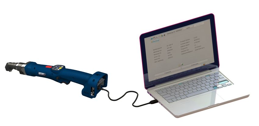
33   5 Display
PAGE

            5.1      Display indicators                  33
            5.2      HST-Tool-Manager                    39
            5.2.1    Setup                               42
            5.2.2    General → Process control           42
            5.2.3    General → Energy & Lighting         44
            5.2.4    General → Features                  45
            5.2.5    General → TM version                46
            5.2.6    Management                          47
            5.2.7    Signals → OLED-display              48
            5.2.8    Signals → LED                       49
            5.2.9    Signals → Sound signals             50
            5.2.10   Signals → Vibration alarm           51
            5.2.11   Graphics                            52
            5.2.12   System time                         53
            5.2.13   Basic settings                      54
            5.2.14   Update                              55
            5.2.15   Programs                            56

       57   6 Accessories
PAGE

       58   7 Storage
PAGE

       59   8 Technical data
PAGE

            8.1      Technical data for all tool types   59
            8.2      Pistol tool                         60
            8.3      Angle tool                          62
            8.4      Straight tool                       70

       72   9 Troubleshooting and Fault repair
PAGE

       73   CE Declaration of conformity
PAGE

                                                           -3-
1 Operating principles

  Dear customers,

  thank you for choosing a HS-Technik GmbH product.

  This quality product „Made in Germany“ fulfils the highest requirements with regard to
  performance, quality and accuracy. When used correctly the product will undoubtedly
  perform very well for many years.

  These operating instructions contain information on safety and for the operation of the
  tool. In addition it contains information on the dimensions and technical data. We would
  be happy to assist you with additional information or to answer your questions. Our
  technical support and our technicians would be happy to assist you.

      1.1     Scope of delivery

  • Battery tightening tool
  • USB Cable (Type A on Mini B)
  • Operating instructions

      1.2     General information

  Read the operating instructions before initial operation. Please pay particular attention
  to Chapter 2 „General Safety Notes“.

  This operating instruction should make it easier for the operator to get to know the tool
  and to use it for its intended purpose. The operating instructions include important
  information related to the safe and proper operation of the tool. Compliance with these
  instructions helps you to:

  • Avoid hazards
  • Avoid repair costs and downtimes
  • Increase the reliability and the lifespan of the product.

-4-
This operating instructions must be read and applied by every person who is assigned to
conduct work using this tool.

In addition to these operation instructions the applicable regulations on accident
prevention and environmental protection should be observed.

          NOTE
          After reading, keep the operating instructions in a place accessible to every
          operator. If you have any further questions, please feel free to contact us.

   1.3     Signs and symbols used

The following signs and symbols will be used in this operating instruction or on the
product:

Symbol                                Explanation

                                      Read this operating instructions

                                      Do not dispose with household waste

                                      Do not dispose the battery in a fire

                                      Do not throw the battery into water

                                      EU conformity marking

®                                     Registered trademark

                                                                                          -5-
1.4    Structure of the warnings

  The warnings are structured as follows:

                  DANGER
                  Indicates an immediate dangerous situation that can lead to serious or even
                  deadly injuries and/or that could seriously damage or even destroy the tool.

                  WARNING
                  Indicates a potentially dangerous situation that can lead to serious injuries
                  and/or damage to the tool.

                  NOTE
                  Important and useful information on using this tool.

            1.5    Technical terms and abbreviations used

      Abbreviation                  Meaning
      °C                            Degrees Celsius, temperature
      AC                            Alternate current
      Ah                            Amp hours, electric charge, battery capacity
      ahv                           Overall vibration
      dB(A)                         Decibels, sound pressure level (A-weighted)
      DC                            Direct current
      Hz                            Hertz, Frequency
      Li-Ion                        Lithium-ion, battery technology
      LpA                           Emission sound pressure level, workplace-related
      m/s²                          Acceleration, Vibration

-6-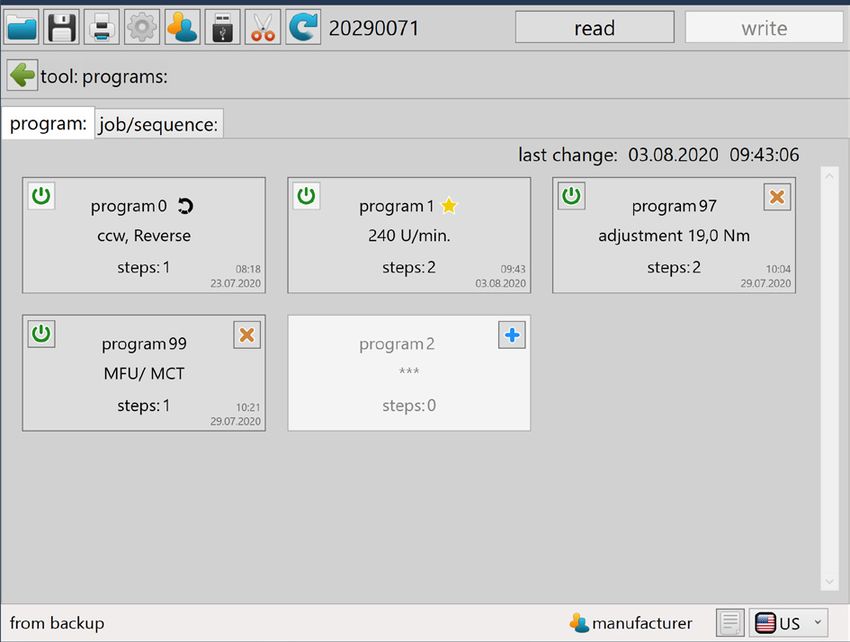
Abbreviation                  Meaning
min   -1
                              Revolutions per minute, Speed
mNN                           Meters above sea level, height
SN                            Serial number
V                             Volts, electrical voltage
W                             Watts, electrical power
Nm                            Newton meters, torque

     1.6    Intended use

This battery tool was designed to prepare screw connections.
The tool may only be used for this purpose as described in this operating instructions.
Only materials that are suitable for this type of tool may be used.

           WARNING
           Intended use also includes
           • following all indications of the operating instructions and
           • observance of inspection and maintenance works.

Any other use or use beyond that is considered improper use. HS-Technik GmbH is not
liable for any damage resulting from this.

                                                                                      -7-
1.7    Improper use

            DANGER
            The use of this tool for other purposes, e.g. for hammering, is not permitted.
            Improper use or incorrect accessories can lead to dangers with unforeseeable
            consequences.

  We accept no liability for damage and malfunctions resulting from non-observance of
  these operating instructions and improper use.

      1.8    Duties of the operator

  The operator undertakes to only allow people who are familiar with the basic regulations
  on work safety and accident prevention and who have been trained on how to use the
  tool at the workplace and to work with this tool.

  The safety awareness of the personnel while working has to be reviewed at regular
  intervals.

  In addition it is necessary to define safety measures for operator protection which are
  based upon an estimation of the vibration load during actual conditions of use.

      1.9    Duties of personnel

  Prior to its use all people who work with this tool are obligated to inform themselves of
  the applicable workplace safety and accident prevention regulations for this power tool
  and to observe them.

  It is recommended that every operator wears hearing protection.

-8-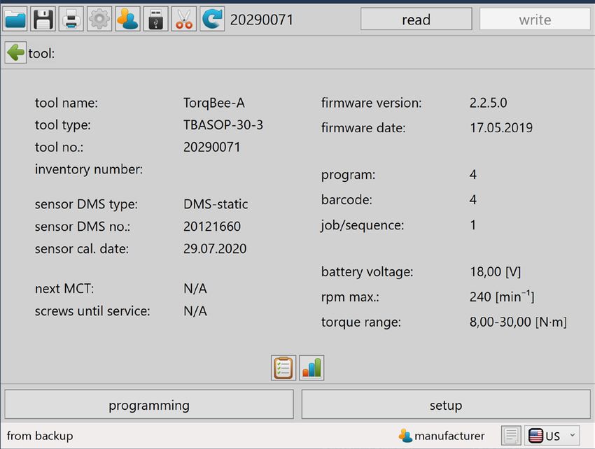
1.10    Training of personnel

Only trained and instructed personnel should work with this tool. The responsibilities of
the personnel must be clearly defined. Trainees may only work with this power tool under
the supervision of an experienced person.

   1.11    Guarantee and liability

Guarantee and liability claims for personal injury and property damage are excluded, if
caused by one or more of the following:

• improper use
• failure to observe these operating instructions
• improper installation, commissioning, operation and maintenance of the device
•	Operating the device with defective safety devices or improperly installed, or non-
   functioning safety and protective devices
•	Failure to observe the information in the operating instructions regarding transport,
   storage, assembly, commissioning, operation and maintenance of the device
• unauthorised structural modifications to the device
• improperly performed repairs
• catastrophes due to external influences and acts of God

                                                                                        -9-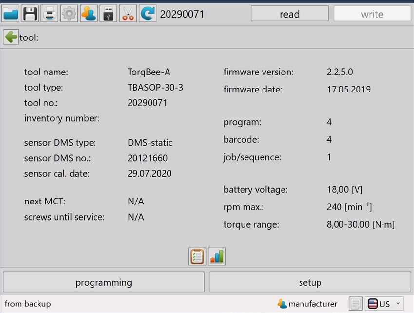
1.12    Copyright

    These operating instructions are intended solely for the operator and its personnel.

    They contain guidelines and information which may not be fully, or partially

    • reproduced
    • distributed or
    • otherwise shared.

    The copyright of these operating instructions is retained by HS-Technik GmbH.

    Manufacturer’s address:

    Im Martelacker 12
    D-79588 Efringen-Kirchen

    Telephone:    +49 (0)7628 - 91 11-0
    Fax:          +49 (0)7628 - 91 11-90
    E-mail:       info@hs-technik.com
    Internet:     www.hs-technik.com

- 10 -
2 General safety information for power tools
DANGER
Read all the safety information, instructions, illustrations and technical data
which is provided with this power tool. Failure to follow the instructions
below may result in electric shock, fire and/or serious injury.
WARNING
This power tool was manufactured in according with current state-of-the-art
technology and recognised technological safety guidelines. However, its use
may jeopardise the health and life of the user or third parties, or risk damage
to other property.
WARNING
The workplace must only be used in accordance with its intended use and in
technically perfect condition.
NOTE
Keep all safety information and instructions for the future.
NOTE
Only have your device repaired by qualified professional staff and only with
original replacement parts which are available at HS Technik GmbH. This
ensures that the safety of the device is maintained.
The term „power tool“ used in the safety information refers to mains-operated power
tools (with mains cable) and to battery-operated power tools (without mains cable).
2.1 Occupational safety
a) Keep your work area clean and well-lit. Cluttered or dark work areas can lead to accidents.
b) Do not work with the power tool in an explosive environment in which there are
flammable liquids, gases or dust. Power tools generate sparks that can ignite the dust
or fumes.
c) Keep children and other people away while using the power tool. You can lose control
of the power tool if you are distracted.
- 11 -2.2 Electrical safety
a) Avoid body contact with grounded surfaces such as pipes, heaters, stoves and refrig-
erators. There is an increased risk of electric shock if your body is grounded.
b) Keep power tools away from rain or moisture. Penetration of water into a power tool
increases the risk of electric shock.
c) Do not misuse the connection cable in order to carry, or hang up the charger, or to
pull the plug out of the socket. Keep the connection cable away from heat, oil, sharp
edges or moving parts. Damaged or tangled connection cables increase the risk of
electric shock.
d) If operating the charger in a damp environment cannot be avoided, use a fault-
current circuit breaker. The use of a residual-current circuit breaker reduces the risk of
electric shock.
e) Check the electrical equipment regularly. Immediately remove loose connections and
scorched cables. Loose connections or scorched cables can lead to electric shock and
risk of fire.
2.3 Safety of people
a) Be alert, pay attention to what you are doing and take care when you are working
with a power tool. Do not use a power tool when you are tired or under the influence
of drugs, alcohol or medication. A moment of inattention while using the power tool
can result in serious injury.
b) Wear personal protective equipment and always safety glasses. Wearing person-
al protective equipment such as a dust mask, non-slip safety shoes, safety helmet or
hearing protection, depending on the type and use of the power tool, lowers the risk
of injury.
c) Prevent accidental starting. Ensure that the power tool is switched off before you
connect it to the power supply and/or the battery, pick it up or carry it. Accidents
can occur if you have your finger on the switch while carrying the power tool or if you
connect the power tool to the power supply when it is switched on.
d) A
void abnormal postures. Make sure you have a secure footing and keep your
balance at all times. This gives you better control of the power tool in unexpected
situations.
- 12 -e) Wear suitable clothing. Do not wear loose clothing or jewellery. Keep hair and cloth-
ing away from moving parts. Loose clothing, jewellery or long hair can get caught in
moving parts.
f) Do not lull yourself into a false sense of security and do not disregard the safety rules
for power tools, even if you are familiar with the power tool after repeated use. Care-
less action can lead to serious injuries within a split second.
g) Actively avoid accidentally switching on the power tool. If the tool is to be in idle
mode for a long time, remove the battery beforehand. This prevents unintentional
start-up.
2.4 Use and handling of power tools
a) Do not overload the power tool. Use the power tool specific for the work you are do-
ing. With the appropriate power tool you will work better and more safely in the power
range indicated.
b) Do not use any power tool which has a defective switch. A power tool which can no
longer be switched on or off is dangerous and must be repaired.
c) Remove the detachable battery before you make changes to device settings,
change application tool parts or put away the power tool. This precaution prevents
unintentional start up of the power tool.
d) Keep unused power tools out of the reach of children. Do not let anyone use the pow-
er tool who is not familiar with it or has not read this operating instructions. Power
tools are dangerous when used by inexperienced people.
e) Maintain power tools and the application tool with care. Check whether moving
parts function properly and do not jam, whether parts are broken or damaged in such
a way that the function of the power tool is affected. Have damaged parts repaired
before using the power tool. Many accidents are caused by poorly serviced power
tools.
f) Keep the tool sharp and clean. Carefully maintained tools jam less often and are
easier to manage.
g) Use power tools, application tools, etc. in accordance with these instructions. While
doing so observe the work conditions and the activities to be performed. The use of
power tools for anything other than the intended application can lead to dangerous
situations.
- 13 -h) Keep handles and gripping surfaces dry, clean and free of oil and grease. Slippery han-
dles and gripping surfaces do not allow safe operation and control of the power tool in
unforeseen situations.
i) Use the correct power tool. Do not use under-performing tools for heavy loads. Do not
use tools for purposes and work for which they are not intended.
j) Check your device for damage. Before continued use of the tool safety equipment
must be tested for proper and intended function. Check whether the function of mov-
ing parts is okay, whether they do not jam, whether any parts are broken, whether all
other parts function properly and whether all conditions which must be met for the
proper operation of the device have been met. Damaged protective devices and parts
should be properly repaired, or replaced by trained customer service unless otherwise
specified in this operating instructions. Damaged switches must be replaced by a cus-
tomer service workshop. Do not use any tools which cannot be properly switched on
and off using the start button.
2.5 Use and handling of battery tools
a) Charge the battery only with charging devices which are recommended by the man-
ufacturer. There is a risk of fire if the battery is used on an unsuitable charger and the
battery can be permanently damaged.
b) Use only the specifically designated battery for the power tool. The use of other
batteries can lead to injuries and the risk of fire.
c) Keep the unused battery away from paper clips, coins, keys, nails, screws or other
small metal parts which could cause a bypass of the contacts. Do not open the
battery and do not short circuit it. A short circuit between the battery contacts can
lead to burns or fire.
d) Fluid can leak out of the battery in the event of incorrect use. Avoid contact with it. In
the event of accidental contact with skin rinse with water. If the fluid comes into con-
tact with the eye seek medical help. Leaking battery fluid can lead to skin irritations or
burns.
e) Do not use damaged or altered batteries. Damaged or altered batteries can behave
unpredictably and can lead to fire, explosion or injury.
f) D
o not expose a battery to fire or high temperatures. Fire or temperatures above
130°C can cause an explosion.
- 14 -g) Follow all instructions for charging and never charge the battery or the battery tool
outside of the temperature range specified in the operating instructions. Incorrect
charging or charging outside of the approved temperature range can damage the bat-
tery and increase the risk of fire.
2.6 Service
a) Only have your power tool repaired by qualified professional staff and only with orig-
inal replacement parts which can be available at HS Technik GmbH. This ensures that
the safety of the power tool is maintained.
b) Never perform maintenance on damaged batteries. All maintenance of batteries may
only be completed by the manufacturer or authorised customer service locations.
- 15 -3 Important information about this tool
3.1 Handling the associated lithium ion battery
a) Observe the operation instructions of the Li-Ion battery.
b) If the battery will not be used over a longer period of time it may not remain on the
charger or on the machine. If an interruption of work of more than 3 hours is expected
the battery must be removed from the tool. Otherwise it cannot be ruled out that the
battery will be permanently damaged.
c) For safety reasons the Li-Ion battery should not remain on the activated charger for
longer than 36 hours. Remove the battery from the charger as soon as possible after
charging is complete.
d) An empty battery should not be in contact with the machine or a charger disconnect-
ed from the mains for a longer period of time. In both instances low currents flow
which totally discharge the battery and can permanently damage it.
e) Always charge the Li-Ion battery as soon as possible after use and do not store it
when empty. If the battery is stored separately from the tool and the charger it’s
capacity will remain constant for a long period of time (loss approx. 5 % per year).
f) Always transport the battery separately from the machine if possible. This prevents
accidental switching on of the machine as well as a total discharge of the battery.
g) Do not subject the Lithium-Ion battery to high temperatures (above 50˚C) or direct
sunlight. If the battery gets warmer than 50°C during operation (charging or discharg-
ing) it must be immediately separated from the charger or the tool.
h) Under extreme use or temperature conditions batteries may leak. In the event of a
leaky battery avoid contact with the skin or eyes. The battery fluid is corrosive and
can cause chemical burns to tissue. If the fluid comes into contact with the skin it must
be washed immediately with soap and water and then rinsed with lemon juice or
vinegar. If the fluid comes into contact with the eyes they must be rinsed for at least 10
minutes with water and a doctor must be consulted immediately.
i) Ensure that the Li-Ion battery does not fall or is not subjected to vibrations or shocks.
j) Clean the battery contacts regularly with a cotton swab dipped in high-proof alcohol.
NOTE
Lithium-Ion batteries have almost no self-discharge and have no memory
effect. With proper and professional handling your tool will be reliably
supplied with high energy density for a long period of time.
- 16 -3.2 Information on the associated charger
a) Observe the operating instructions of the charger.
b) The charger may not be connected to a step-up converter, generator or a direct
current outlet.
c) Ensure that the ventilation slots on the charger are not covered or blocked.
d) Never charge the battery inside a box or a closed container. The battery may only be
charged in a well ventilated location.
e) Do not charge the battery at temperatures BELOW 10°C or ABOVE 40°C.
f) D
o not store the power tool, the charger and the battery in locations in which
temperatures are above 50°C. In particular, avoid direct sunlight.
3.3 Structural modifications
No changes, additions or conversions to the power tool may be made without the approval
of the manufacturer.
All conversion measures require written permission and confirmation by HS-Technik GmbH.
WARNING
In the event of the replacement of wear and tear parts only original
replacement parts may be used.
- 17 -3.4 Cleaning the device and disposal
Substances and materials used must be handled and disposed of properly, particularly
when cleaning with solvents.
Do not throw the used battery into the household waste, fire or water, instead have it
professional disposed of by a specialist or the manufacturer.
- 18 -4 Start-up and use
DANGER
Risk of injury from damaged tools
Damaged tools can lead to injuries or damages.
• All damaged parts must be repaired before use.
Risk of injury from falling tools
Falling tools can lead to injuries or damages.
• Ensure you are self-belayed and have a secure footing.
• Avoid dropping the tool.
Risk of burns due to hot exhaust air
Hot air can escape through exhaust openings.
• Do not place any sensitive body parts directly in front of exhaust openings.
Risk of injury due to improper use
Improper use can lead to injuries or damage.
• Use the tool only for the intended purposes.
Risk of injury from substances
Substances such as lubricating oil and grease are flammable on the skin.
• Avoid contact with such substances.
• Should you still come into contact wash the affected area carefully.
NOTE
Maintain your tool with care. Follow the operating instructions during
maintenance and cleaning. Keep the handle free of lubricants and dirt.
NOTE
Do not drop the tool, and do not let any other objects fall onto the tool.
Protect it from impacts.
NOTE
Ensure that the tool does not come into contact with splashing water or oil.
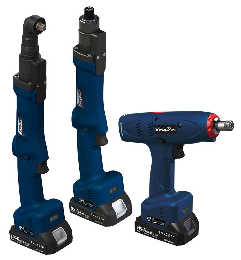
- 19 -4.1 Tool structure
1. OLED Display* 10. LED for work area lighting
2. Multi-colour LED 11. Optional Wi-Fi*
3. Brushless motor 12. Optional barcode scanner*
4. Colour coding 13. 18 V Li-ion battery
5. Clutch entry** 14. 1/4”-hexagon socket tool holder
6. Clockwise/counter clockwise direction 15. 3/8"-Square tool holder,
7. Start button 1/4" Square (TBAx-10 and 5) and
8. Ergonomic grip 1/2" (starting from TBAx-85)
9. USB Port
4 5 4
2
1 14
3 10
6 7
1
8
11
12
9
13
* not available in the Light version
** not available in the ECO, EC and EC2 Version
- 20 -15
10
5
3
4
1
6 2
7
8
11
9 12
13
- 21 -14
5
10
3 4
1
6 2
7
8
11
9 12
13
- 22 -NOTE
Depending on the tool configuration various functions, which are described in
the operating instructions, may be used. In addition these basic functions are
associated with several sub-functions.
Included in the scope of delivery Optional
Shut-off Torque Reaction OLED Barcode
Article Wi-Fi
clutch transducer sensor display reader
TBPL-xx •
TBPSO-xx • • • •
• • • • •
Pistol tool
TBPSOP-xx
TBPECO-xx • • • •
TBPEC-xx • • • •
TBPEC2-xx • • • • •
TBAL-xx •
TBASO-xx • • • •
• • • • •
Angle tool
TBASOP-xx
TBAECO-xx • • • •
TBAEC-xx • • • •
TBAEC2-xx • • • • •
TBSL-xx •
TBSSO-xx • • • •
Straight tool
TBSSOP-xx • • • • •
TBSECO-xx • • • •
TBSEC-xx • • • •
TBSEC2-xx • • • • •
- 23 -4.2 Operation
4.2.1 Inserting and removing the battery
• In order to insert the battery (1), align it so that it can be easily pushed onto the mount-
ing provided along the plastic guide. After sliding it on completely, the fastening clip (2)
must lock the battery firmly and properly into place in the tool housing.
• In order to remove the battery push the fastening clip on the front side of the battery
down and pull the battery forward and off.
• Don't use force to install the battery. If the battery can not be easily pushed on it was not
correctly positioned.
NOTE
Always push the battery all the way in until it locks into place with a click.
WARNING
Risk of injury from falling battery
If the battery is not correctly locked it can fall out and cause injuries.
• Always ensure that the battery is fully locked into place.
1
2
1 - Battery
2 - Fastening clip
- 24 -4.2.2 Press start button
Pressing or releasing the start button starts or stops the tool.
NOTE
The tool only starts up when the battery has sufficient capacity.
* *
* – Start button
4.2.3 Clockwise / Counterclockwise rotation switch
WARNING
Risk of injury as a result of accidental actuation of the start button
When pulling the battery off the start button can accidentally be actuated.
• Ensure that the direction of rotation switch is in the „neutral“ position
• The tool has a slide switch to change the direction of rotation. Only use the slide switch
after the tool has come to a complete stop. Changing the direction of rotation during
operation will damage the device.
• Always put the slide switch in the neutral position when you are not using the tool.
• In order to change the direction, or set it, press the direction of the slide switch out to
the left for clockwise direction or out to the right for counter clockwise direction .
When the direction of slide switch is in the centre position the start button can not be
actuated.
* *
* – Clockwise / Counterclockwise slide switch
- 25 -4.2.4 LED / Barcode scanner
WARNING
Risk of injury from the light emitting diode
Looking directly into the light emitting diode can lead to eye injuries.
• Never look directly into the light emitting diode.
After pressing the start button, the LED and the barcode scanner switch on. The afterglow
time of the LED can be defined in the HST-Tool-Manager under Settings - General after
actuating the start button. The barcode scanner turns off after the barcode has been suc-
cessfully scanned in and / or the start button has been actuated.
NOTE
Do not clean LED with harsh cleanser!
NOTE
The optional barcode scanner must be activated according in the HST-Tool-
Manager Software under the hardware settings, so that it can be used.
4.2.5 Control light with multi-colour LED
The TorqBee® series has a LED control function, located near the display around the tool.
This informs the worker at all times about the current tool status:
The LED can be programmed as steady, flashing or pulsating with different time settings
and different colours for each LED signal.
Information concerning programming can be found in the HST-Tool-Manager operating
instructions.
Colours:
- 26 -4.2.6 Setting the tightening torque at pistol tools
With the TorqBee® Light / TorqBee® SO / TorqBee® SOP series, the tightening torque is set
using a mechanical shut-off clutch.
• To adjust the clutch, the protective clip must first be removed from the clutch.
• To do this lightly press the clip down. It can then be easily pushed to the back. The clutch
becomes visible.
• The clutch can now be set using a setting tool.
Counterclockwise: weaker
Clockwise: stronger
• After setting, the clip can be pushed back to the front. It then locks automatically.
Now the torque must be determined using a suitable torque gauge. If the desired value
was not reached the clutch must be readjusted.
DANGER
Risk of injury from protruding objects.
Objects which are placed in the opening can be ejected during operation.
• The clutch has to be be closed prior to operation.
• Ensure that there are not objects in the opening.
2
1
3
1 – Press clip down 3 – Clutch adjustment
2 – Push clip back
- 27 -In the TorqBee® ECO, EC and EC² series the tool is programmed using the HST-Tool-
Manager Software. Make sure that the tool is properly configured and parametrised.
NOTE
See HST-Tool-Manager operating instructions.
4.2.7 Setting the tightening torque at angle & straight tools
With the TorqBee® Light, SO and SOP series, the tightening
torque is set using a mechanical shut-off clutch.
• T o adjust the clutch, the clutch cover must first be rotated to
the open position.
•W
hen the clutch is visible bring the clutch into the setting posi-
Rotate the cover
tion, e.g. by turning the output or quickly starting up the tool.
• T he clutch can now be set using a setting tool.
Counterclockwise: weaker
Clockwise: stronger
• After adjusting, slide the cover back over the clutch opening.
Clutch adjustment
•N
ow the torque must be determined using a suitable torque
gauge. If the desired value was not reached the clutch must be
readjusted.
DANGER
Risk of injury from protruding objects.
Objects which are placed in the opening can be ejected during operation.
• The clutch must has to be closed prior to operation.
• Ensure that there are not objects in the opening.
- 28 -4.2.8 Cancel order
If you want to execute an order later or if you scanned an incorrect
barcode you can cancel it after it was enabled.
To do this press and hold the menu button (middle display button)
for approx. 3 seconds. The cancel symbol will appear. Confirm this
with the left display button.
4.2.9 Set-up menu
NOTE
In order to get into the setup menu the „Setup Menu“ must be activated
under general settings in the HST-Tool-Manager software. Also activate
„scanner selectable“ so that „scanner” can be selected in the setup menu
item. If you also activate „Manual mode selectable“ the setup menu items
„M“ and „Scanner M“ will be enabled. In order to be able to select different
programs per display the check mark next to „manual mode active“ must also
be selected.
1. Button for menu activation and selection
4 2. Button for decreasing value (-)
3. Button for increasing value (+)
2 3 4. State of charge display
1
You will reach the set-up menu by pressing and holding the yellow display button for a
longer period of time.
- 29 -The following points are available in the set-up menu:
The current battery voltage, RSSI network coverage, and the
firmware version can be displayed under menu item „Info“.
The scanner can be selected under the scanner menu item in
order to read in the network settings using a barcode. Scanning
for program selection is not possible in this mode.
A program from the list of saved programs can be selected un-
der the program menu item.
Manual mode can be selected under menu item M
(M = manual mode).
This activates the „standard program“ (yellow star).
The scanner can be selected under the scanner M menu item in
order to read barcodes for program selection. The barcodes and
their assignment to a program must be saved in the tool.
You can leave the setup menu by selecting the menu item „Exit“.
The tool reverts back to normal operation.
- 30 -If the connection to the sequence control (radio connection via access point) is cancelled
and a work order was already approved in the tool this should continue to be executed
if possible. Even after completion of the work order the tool will attempt to send the
tool results. If the connection to the sequence control can not be re-established the tool
results must be saved manually (read and save tool with HST-Tool-Manager software).
Then work can be continued with the emergency strategy after the battery has been
removed.
To do this hold down the start button and push the battery up.
After approx. 3 seconds the „set-up symbol“ appears in the display. You can now release
the start button to get to the set-up menu.
By pressing the menu button (middle display button) you will get to the next menu item.
By pressing the start button you can select a menu item.
Confirm your selection using the left key, cancel the selection using the right key.
Select scan mode under menu item „Scanner M“ in order to scan the barcode for program
selection. Scan the barcode for the screw joint as you would during regular operation. After
this you will receive approval for the corresponding program with the number of screws.
The tool results will not be sent to the sequence control for central storage. However, you
can read out the tool results using the HST-Tool-Manager software and save it as a file.
Use the menu button to move forward until the „Scan M“ logo appears. The tool must be
programmed accordingly with the HST-Tool-Manager.
Push the start button in order to select the setting.
- 31 -In order to confirm the emergency strategy with the scan function push the left button
on the display.
4.2.10 Operation
NOTE
Hold the tool with its tool insert straight onto the tightening point with the
required pressure, otherwise it can be damaged (cam-out effect).
In order to ensure the safety and reliability of the product repairs, any other possible main-
tenance or adjustments should be completed by HS-Technik GmbH or an authorised spe-
cialised company.
- 32 -5 Display
5.1 Display indicators
The display indicators can be adjusted in the HST-Tool-Manager so that, for example,
precise values for the fittings, the angle of rotation, only one OK or NOK, or the count
process can be displayed for the worker. The display indications can be shown in German
and English. In addition which unit the values will be provided in (Nm, lbf.in, lbf.ft) can be
set.
Tool serial numbers or program numbers of Counting function:
the active program, e.g.: P03 Counts the processed blind rivets per process instance
e.g. 001/003 means 1. Rivet of 3 processed
Main display window:
The current status, the results of the screw connections, warnings, commands and symbols and
texts for simple control of the tool are displayed for the worker in the main display window.
As a result the worker always immediately knows whether his work was correct, what torque
range is specified for the next screw fitting, or why the tool is not conducting a screw fitting.
Furthermore, the worker is reminded by the integrated battery management to change the
battery before it can become damaged as a result of deep discharge.
P01 001 / 003
IO 02
NmDisplay notification Meaning
19320012 Battery state of charge: 50 % - 100 %
READY
19320012 Battery state of charge: 30 % - 50 %
READY
19320012 Battery state of charge: 10 % - 30 %
READY
19320012 Battery state of charge: 5 % - 10 %
READY
19320012 Battery state of charge: less than 5 %
BATT EMPTY
19320012 The device is ready for use.
READY
P01 001 / 003 The first of three screw connections was successful. Two screw connec-
IO 02 tions have to be completed. Results of the first screw connection are dis-
Nm
3.02Display notification Meaning
19320012 Product ID must be scanned before the tool will be enabled. Symbol may
also be a car.
SCAN BARCODE
Tool is locked and is being configured using the HST-Tool-Manager via
Wi-Fi.
Battery may not be removed.
P03 001/002 The targets could not be reached for the tightening process. Values of
NOK 01 the fitting are displayed.
Nm <
2.70 98
NOK
20.90 V Maximum battery voltage exceeded
Batt over 0
17.00 V Battery voltage not reached
Batt empty 1
P01 002/003 The NOK has to be confirmed by pressing the yellow button.
QUIT
OK
NOK CONFIRM
P01 000/001 The tool has received approval for program 1. One screw should be
3.00 loosened with 3.00 Nm.
Nm
ENABLE 1
P01 000/001 The tool has received approval for program 1. One screw should be
3.00 tightened with 3.00 Nm.
Nm
ENABLE 1
19320012 The tool is searching for the network.
SCAN
19320012 The tool found the network connection and is connecting to it.
JOIN SERVER
- 35 -Display notification Meaning
19320012 Previously lost connection to the network was restored.
reconnect OK
P01 000/001 Releasing the start button during the tightening process is permitted.
NO NUMBER Start button was released during the tightening process. It can be contin-
ued to tighten. When using the barcode scanner the corresponding bar-
RUN R code will be displayed in the blue display indicator.
P01 000/003 Tightening process running
TEST1 When using the barcode scanner the corresponding barcode will be dis-
played in the blue display indicator.
RUN R
P03 000/001 Releasing the start button during the loosening process is permitted. Start
NO NUMBER button was released during the loosening process. It's allowed to contin-
ue to be loosened. When using the barcode scanner the corresponding
RUN L barcode will be displayed in the purple display indicator.
P03 000/001 Loosening process running
NO NUMBER When using the barcode scanner the corresponding barcode will be dis-
played in the purple display indicator as an approval in the case of “NO
RUN L NUMBER”.
P01 002/003 After confirmed NOK (“QUIT OK” display) the screw must first be loos-
ened before the next approval.
REVERSE
P01 001/001 The direction of rotation switch is set to anti-clockwise motion; it may not
be released, the previous NOK fitting must be acknowledged. This can be
programmed in the setting (HST-Tool-Manager).
NO REVERSE
P01 001/001 Start button was already pressed, when the tool got enabled. The start
button must be released before the tool gets enabled.
TRIGGER
P03 000/001 Current redundancy of the torque has been below the limit.
2.85
Nm <
2.85 712
NOK 1 MDP-
P03 000/001 Current redundancy of the torque has been above the limit.
3.04
Nm <
3.04 60
NOK 1 MDP+
- 36 -Display notification Meaning
Worker must examine the screw himself after a tightening process and
P03 000/001
?
then personally acknowledge it afterwards with time input (e.g. 15 sec-
onds) on the display. The timer runs backwards for orientation. (Image is
NOK 10.9
at 10.9 seconds) If he does not acknowledge the screw within the time it
is automatically valued as NOK.
18360035 The period for the machine capability is expired and has to be renewed.
The message can be acknowledged with the yellow display button. It will
appear everytime the tool is powered up.
MCT
18360035 Tool must be serviced and is only approved again after confirmation by
service.
SERVICE
P03 000/002 Maximum tightening time for the enabled program was exceeded.
TIME OUT
P03 000/001 Enabled program is deactivated on this tool.
Nm <
-327 08
NO JOB ACTIVE
P03 000/001 Enabled program does not exist on this tool.
Nm <
-327 08
NO PROG SD
P03 000/001 Enabled program sequence does not exist on this tool.
Nm <
-327 08
NO JOB PARAM
Maximum permissible torque exceeded → Contact the manufacturer
STOP
TORQUE MAX
Maximum permissible current exceeded → Contact the manufacturer
STOP
CUR MAX
Control system overheating → Contact the manufacturer
STOP
TEMP FET
- 37 -Display notification Meaning
Motor overheating → Contact the manufacturer
STOP
TEMP MOT
Maximum logic voltage exceeded, tool must be repaired!
STOP
FAIL VCC MAX
SD-card in tool not available or defective. If the problem cannot be re-
STOP
solved with a new SD card, please contact the manufacturer.
NO SD CARD
19320012 Tool cannot connect to the network.
STOP
WLAN JOIN
19320012 Tool could not find the set network.
STOP
WLAN SCAN
19320012 Tool is in the wrong IP circle.
STOP
WLAN IP
The most common error messages are pictured here. However, because there are many
status and error messages in the field of electronics it is not possible to list them all. If you
encounter a status or error message for which you do not know how to continue you may
contact us at any time. Many displays can vary slightly depending on the software setting.
To this end view your settings and the operating instructions of the HST-Tool-Manager. If
an error appears repeatedly please contact our Support Team.
The display indicators (status notifications) were created partially with and partially with-
out Wi-Fi connection to a higher-level control system. As soon as the power tool is con-
nected to a control system the Wi-Fi symbol is displayed on the battery display.
- 38 -5.2 HST-Tool-Manager
This excerpt shows only the most important functions for this tool type.
A complete guide for the HST-Tool-Manager is available for you to download on our
website.
Download the current version of the HST-Tool-Manager in the downloads area on the HS-
Technik website www.hs-technik.com.
NOTE
Always use the most current version of the HST-Tool-Manager from the
website. The HST-Tool-Manager is backward compatible, i.e. it can also read
and process older tool versions. If an update of your tool is necessary the HST-
Tool-Manager will inform you.
1. Start the HST-Tool-Manager by double clicking the HST-Tool-Manager icon:
2. Log-in with the required User, a list of the passwords can be requested from HS-Technik
(support@hs-technik.com).
- 39 -3. Insert the USB cable included into the Mini-USB socket at the bottom of the tool and the
opposite end into an open USB interface on your laptop / tablet / PC.
4. Click on the „read“ button on the top right.
- 40 -5. The HST-Tool-Manager will now read the settings from your tool and will display its pro-
gress using a green bar. At the end the tool overview will be displayed.
- 41 -5.2.1 Setup
Clicking on setup takes you to the tool settings menu. Here, for example, the display, LED
display or the energy savings settings can be parameterised.
5.2.2 General → Process control
- 42 -„Manual mode active“ If the check box is activated the tool will operate in manual mode. I.e.
the standard program (yellow start) will always be conducted. In this
mode the counting function, Wi-Fi and barcode are deactivated.
„enable over“
The drop-down menu is used to select how the tool will be approved. In
order to use this function manual mode must be deactivated.
- „Start button“
The start button must be pushed 3x quickly in succession in order to
enable the tool. The tool then works in the standard program with the
activated counter.
- „Time“
A time after which the tool will be enabled must be entered. The tool
then works in the standard program with the activated counter.
- „Start button & Time“
A combination of the above described functions. The provision which
is met first enables the tool. The tool then works in the standard pro-
gram with the activated counter.
- „Barcode“
Activates the barcode scanner in the tool. A barcode must be scanned
for the approval. Additional information for programming barcodes
can be found in the operating instructions of the HST-Tool-Manager.
- „External control“
Activates the Wi-Fi in the tool. The tool will now be enabled by an ex-
ternal control (controller). Without approval the tool is locked.
- „Barcode & external control“
Activates the barcode scanner and Wi-Fi. The tool scans a barcode
which is then sent to the external control (controller). Based on the
scan the tool will be enabled via Wi-Fi by the external control.
„reverse enabled for Is used for open flat drives in particular. By activating the check box it's
open crowfoots“ always possible to start the tool in reverse mode.
„Waiting time between If the function is activated a time for the waiting period between two
tightenings“ fittings must be entered. For this period the tool will be without function
between two fittings; it will not start.
„abort on the display“ If the function is activated a time for the interruption of the order must
be pressed for this period in order to cancel the current job. The yellow
menu button must be pressed for this time in order to interrupt an order.
- 43 -5.2.3 General → Energy & Lighting
Here you can parametrise the energy savings options and the LED work lighting.
„Energy saving“ The energy saving options can be activated or deactivated with the
check-box.
„Display shut off after“ Time in seconds without action after which the OLED display of the tool
will switch off and the screen saver is activated.
Default value: 600 seconds (10 minutes)
„Tool shut off after“ Time in seconds without action after which the tool turns off. Default
value: 1,800 seconds (30 minutes)
„LED lighting“ The LED lighting can be activated or deactivated with the check-box.
„Afterglow“ The amount of time the LED lighting continues to glow after completion
of the work process.
- 44 -5.2.4 General → Features
„Setup menu“ Activates and deactivates the setup menu using the display buttons. If
this function is activated you can enter the setup menu by holding down
the yellow menu button on the display.
„Scanner selectable“ If this function is activated you can activate and deactivate the barcode
scanner using the setup menu on the tool.
„Handmode If this function is activated you can activate and deactivate handmode
selectable“ using the setup menu on the tool.
„NOK confirmation Activates and deactivates the NOK confirmation using the yellow menu
active“ button.
„NOK confirmation in Activates and deactivates the NOK confirmation using the yellow menu
manual mode active“ button when the tool is being operated in manual mode.
„NOK confirmation on NOK confirmation on display using the yellow menu button.
display“
„last screw Confirmation of last screw with yellow button on display.
confirmation“
„max fail quit“ A maximum number of errors can be defined. If it is exceeded it must
be acknowledged for approval using the yellow button on the display.
- 45 -5.2.5 General → TM version
The TM version tab will display the HST-Tool-Manager version required for this tool, at
minimum, the version intended for the application, and the version last written with on
the tool.
- 46 -5.2.6 Management
The data on the operating site and the inventory number of the tool can be saved under
administration.
location max. 20 characters
inventory number max. 40 characters
- 47 -5.2.7 Signals → OLED-display
„Language“ Select the language on the OLED display, German or English
Default: English
„display of results“ Select the result presentation on the OLED display.
„Units“ Selection of the physical unit for the torque.
„enable display“ Selection for what is to be displayed on the tool display when the tool
is enabled.
- 48 -5.2.8 Signals → LED
The LEDs around the OLED display can be parametrised under the LED tab. The colour of
the LEDs can be changed by clicking on the coloured square.
„Duration“ The duration of the display in seconds, max. 25.5 seconds.
„Period“ The duration of the sequence of the 10 parametrisable indicator fields.
Period 1.00 seconds means that the 10 fields will be shown one after
another within 1.00 seconds.
- 49 -5.2.9 Signals → Sound signals
„Duration“ For the duration the time of the acoustic signal for OK and NOK results
will be parametrised in seconds, max. value 3.0 seconds.
„at start“ When the check-box is selected a signal will sound when the tool starts.
„during scan“ When the check-box is selected a signal will sound when the tool is
scanned.
- 50 -5.2.10 Signals → Vibration alarm
„Duration“ For the duration the time of the vibration for OK and NOK results will be
parametrised in seconds.
- 51 -5.2.11 Graphics
„Measured“ Selection of the physical parameters of the curve display depending on
the tool type.
- Torque, angle, current, voltage
- Torque, angle, current
- Torque, angle
- Torque
Torque 1, torque 2, MDM/MDP1
Torque 1, torque 2, angle 1, angle 22
„Sampling rate“ Defines the standard sampling rate with which the curve is recorded,
Default 333 Hz.
„lagmax“ Defines the time for which the recording of the graph continues after
reaching the target criteria.
Recommended max. value 0.250 seconds, Default: 0.150 seconds
„Record timemax“ Shows how many seconds can be recorded for the selected criteria per
fitting.
If the recording time is not sufficient the beginning of the recording will
be discarded.
1 Is only available with the EC2 tool type and enables graphic recording of the redundant torque encl. the permissible tolerance (MDM/MDP).
2 Is only available with the EC2 tool type and enables graphic presentation of the redundant torque and the redundant angle.
- 52 -5.2.12 System time
In the system time tab the real time clock (RTC) can be synchronised with the time of the
computer connected.
The real time clock is still supplied with power internally via a capacitor even if the battery
is disconnected from the tool. The internal memory for the RTC can be charged via both
USB and the battery. The internal memory is fully charged after approx. 30 min. In order
for the time stamp of the tool to be correct, the internal memory for the RTC must be fully
loaded at the latest after 2 weeks.
If the system time and the time on the tool amount to a difference of more than 30 seconds
a notification will appear during the read out of the tool.
- 53 -5.2.13 Basic settings
Under „basic settings“ accessories can be activated, such as Wi-Fi and barcode scanner as
well as the recovery function.
Wi-Fi and scanner are automatically activated if these functions are selected under
„General → Process control → Approval via“.
„Display“ Activates and deactivates the OLED display.
„Scanner“ Activates and deactivates the barcode scanner. A prerequisite is that the
tool is equipped with a barcode scanner.
„Wi-Fi“ Activates and deactivates the Wi-Fi module. A prerequisite is that the
tool is equipped with Wi-Fi.
„Recovery“ Activates and deactivates the recovery function.
This function enables the continuation of a screw connection order after
a battery change. This enables a battery change during an ongoing screw
connection order without any loss of data.
- 54 -5.2.14 Update
Select
Click on select and find the .upd file provided by HS-Technik GmbH. Please select automatic
under „Recovery mode“. Then click „start“.
The progress of the update will be displayed using a status bar and confirmed at the end
with „done“. The tool is now up-to-date with the current firmware and has the same
settings as prior to the update.
NOTE
Do not pull out the USB cable during the update process!
- 55 -5.2.15 Programs
Clicking on „Program“ takes you to the program settings menu.
The programs are created here; in doing so many parameters must be set which will have
a large influence on the process.
A detailed guide on this can be found in the operating instructions of our HST-Tool-Manager
(download at www.hs-technik.com/software)
NOTE
We recommend using the support of the HS-Technik service personnel
during initial start-up in order to determine the perfect parameters for your
application.
- 56 -6 Accessories
WARNING
Incorrect use of possible accessories, or accessories from other manufacturers
could present a risk (of injury) to persons.
NOTE
Only use accessories for their stated purpose. Please contact us at any time,
should you have any queries.
An exploded view and a replacement parts list can be requested from us with specification
of the Item no. at info@hs-technik.com or by telephone at +49 (0) 7628 / 9111-0.
NOTE
All tools will be delivered with software.
HST-3123
Adjustment tool for:
- TBxL
- TBxSO
- TBxSOP
HST-3580
Mounting (without balancer) for:
- TBAEC-30 - TBAEC2-30
- TBAEC-55 - TBAEC2-55
- TBAEC-85 - TBAEC2-85
HST-3581
Adaption for torque discharge arms:
- TBAEC-55 - TBAEC2-55
- TBAEC-85 - TBAEC2-85
- 57 -7 Storage
Observe the following information when storing tools, batteries and chargers:
• Remove the battery when you are not using the tool.
• If you will not be using the battery for a longer period of time it should be stored, fully
charged, in a dry, dust-proof area.
• Store the tool and charger in a dry environment protected against splashing water.
• Store the tool and charger in a well ventilated space and protected against exposure to
dust.
• Ensure that the storage environment is free of aggressive chemicals and vapours.
- 58 -8 Technical data
8.1 Technical data for all tool types
Description TBXXX-Y
Operating voltage 18 VDC
Noise emissions (LpA) < 72 dB(A)
Measurement uncertainty (KpA) 2.5 dB(A)
Vibration (ahv) < 2.5 m/s²
Measurement uncertainty (Khv) 0.1 m/s²
Operating altitude < 2000 mNN
Operating temperature 10 - 40 °C
Storage temperature 0 - 50 °C
HST-PR-1825 battery (weight) Li-Ion, 18 V, 2.5 Ah (350 g)
HST-PR-1850 battery (weight) Li-Ion, 18 V, 5.0 Ah (600 g)
HST-PR-2830 charger 220 - 240 VAC, 50 - 60 Hz, 65 W
The values given for noise emissions and vibration were measured using a standardised
test method and can be used for comparison with other power tools. They can also be
used for a preliminary estimate of the load.
NOTE
The actual emissions can differ from the above information depending on the
type and manner of use of the tool and, in particular, depending on the type
of work-piece.
- 59 -8.2 Pistol tool
TorqBee Light Torque Max. speed Tool adapter Dimensions L × W × H Weight
TBPL-4 1.0 - 4.0 Nm 1,300 rpm 1/4" - Form E 230 × 72 × 211 mm 1.20 kg
TBPL-6 2.0 - 6.5 Nm 1,040 rpm 1/4" - Form E 230 × 72 × 211 mm 1.20 kg
TBPL-10 2.0 - 9.0 Nm 740 rpm 1/4" - Form E 230 × 72 × 211 mm 1.20 kg
TBPL-12 3.0 - 13.0 Nm 530 rpm 1/4" - Form E 230 × 72 × 211 mm 1.20 kg
TorqBee SO Torque Max. speed Tool adapter Dimensions L × W × H Weight
TBPSO-4* 1.0 - 4.0 Nm 1,300 rpm 1/4" - Form E 230 × 72 × 211 mm 1.20 kg
TBPSO-6* 2.0 - 6.5 Nm 1,040 rpm 1/4" - Form E 230 × 72 × 211 mm 1.20 kg
TBPSO-10* 2.0 - 9.0 Nm 740 rpm 1/4" - Form E 230 × 72 × 211 mm 1.20 kg
TBPSO-12* 3.0 - 13.0 Nm 530 rpm 1/4" - Form E 230 × 72 × 211 mm 1.20 kg
TorqBee SOP Torque Max. speed Tool adapter Dimensions L × W × H Weight
TBPSOP-4* 1.0 - 4.0 Nm 1,300 rpm 1/4" - Form E 230 × 72 × 211 mm 1.20 kg
TBPSOP-6* 2.0 - 6.5 Nm 1,040 rpm 1/4" - Form E 230 × 72 × 211 mm 1.20 kg
TBPSOP-10* 2.0 - 9.0 Nm 740 rpm 1/4" - Form E 230 × 72 × 211 mm 1.20 kg
TBPSOP-12* 3.0 - 13.0 Nm 530 rpm 1/4" - Form E 230 × 72 × 211 mm 1.20 kg
TorqBee ECO Torque Max. speed Tool adapter Dimensions L × W × H Weight
TBPECO-12* 2.0 - 14.0 Nm 530 rpm 1/4" - Form E 230 × 72 × 211 mm 1.20 kg
TorqBee EC Torque Max. speed Tool adapter Dimensions L × W × H Weight
TBPEC-10* 0.8 - 11.0 Nm 740 rpm 1/4" - Form E 230 × 72 × 211 mm 1.15 kg
TBPEC-12* 1.0 - 14.0 Nm 530 rpm 1/4" - Form E 230 × 72 × 211 mm 1.15 kg
TorqBee EC2 Torque Max. speed Tool adapter Dimensions L × W × H Weight
TBPEC2-10* 0.8 - 11.0 Nm 800 rpm 1/4" - Form E 230 × 72 × 211 mm 1.15 kg
TBPEC2-12* 1.0 - 14.0 Nm 550 rpm 1/4" - Form E 230 × 72 × 211 mm 1.15 kg
* W = Wi-Fi option
B = Barcode scanner option
WB = Wi-Fi & Barcode scanner option
Dimensions and weight data without battery.
- 60 -52
hexagon DIN 3126-F6,3
Innensechskant DIN 3126-F6,3
231
26
18
244
75
TBPx
Specifications in mm
Not shown to scale
- 61 -8.3 Angle tool
TorqBee Light Torque Max. speed Tool adapter Dimensions L × W × H Weight
TBAL-10-2 (4) 2.0 - 9.0 Nm 740 rpm 1/4” square 440 × 72 × 94 mm 1.50 kg
TBAL-12-3 3.0 - 13.0 Nm 480 rpm 3/8” square 455 × 72 × 94 mm 1.51 kg
TBAL-20-3 5.0 - 20.0 Nm 340 rpm 3/8” square 455 × 72 × 94 mm 1.51 kg
TBAL-30-3 15.0 - 30.0 Nm 200 rpm 3/8” square 510 × 72 × 94 mm 2.20 kg
TBAL-45-3 15.0 - 45.0 Nm 120 rpm 3/8” square 510 × 72 × 94 mm
TBAL-55-3 (5) 25.0 - 55.0 Nm 120 rpm 3/8” square 580 × 72 × 94 mm 2.60 kg
TBAL-85-5 30.0 - 85.0 Nm 80 rpm 1/2” square 630 × 72 × 94 mm 3.00 kg
TBAL-100-5 35.0 - 100.0 Nm 70 rpm 1/2” square 960 × 72 × 94 mm 3.50 kg
TorqBee SO Torque Max. speed Tool adapter Dimensions L × W × H Weight
TBASO-10*-2 (4) 2.0 - 9.0 Nm 740 rpm 1/4” square 440 × 72 × 94 mm 1.50 kg
TBASO-12*-3 3.0 - 13.0 Nm 480 rpm 3/8” square 455 × 72 × 94 mm 1.51 kg
TBASO-20*-3 5.0 - 20.0 Nm 340 rpm 3/8” square 455 × 72 × 94 mm 1.51 kg
TBASO-30*-3 15.0 - 30.0 Nm 200 rpm 3/8” square 510 × 72 × 94 mm 2.20 kg
TBASO-45*-3 15.0 - 45.0 Nm 120 rpm 3/8” square 510 × 72 × 94 mm 2.20 kg
TBASO-55*-3 (5) 25.0 - 55.0 Nm 120 rpm 3/8” square 580 × 72 × 94 mm 2.60 kg
TBASO-85*-5 30.0 - 85.0 Nm 80 rpm 1/2” square 630 × 72 × 94 mm 3.00 kg
TBASO-100*-5 35.0 - 100.0 Nm 70 rpm 1/2” square 960 × 72 × 94 mm 3.50 kg
TorqBee SOP Torque Max. speed Tool adapter Dimensions L × W × H Weight
TBASOP-10*-2 (4) 2.0 - 9.0 Nm 740 rpm 1/4” square 440 × 72 × 94 mm 1.50 kg
TBASOP-12*-3 3.0 - 13.0 Nm 480 rpm 3/8” square 455 × 72 × 94 mm 1.51 kg
TBASOP-20*-3 5.0 - 20.0 Nm 340 rpm 3/8” square 455 × 72 × 94 mm 1.51 kg
TBASOP-30*-3 15.0 - 30.0 Nm 200 rpm 3/8” square 510 × 72 × 94 mm 2.20 kg
TBASOP-45*-3 15.0 - 45.0 Nm 120 rpm 3/8” square 510 × 72 × 94 mm 2.20 kg
TBASOP-55*-3 (5) 25.0 - 55.0 Nm 120 rpm 3/8” square 580 × 72 × 94 mm 2.60 kg
TBASOP-85*-5 30.0 - 85.0 Nm 80 rpm 1/2” square 630 × 72 × 94 mm 3.00 kg
TBASOP-100*-5 35.0 - 100.0 Nm 70 rpm 1/2” square 960 × 72 × 94 mm 3.50 kg
- 62 -You can also read


