Quick Start Guide - XNX Universal Transmitter
←
→
Page content transcription
If your browser does not render page correctly, please read the page content below

Quick Start Guide

XNX Universal Transmitter


WARNINGS
     »» The XNX Universal Transmitter is certified and designed for installation and
        use worldwide in hazardous areas.
     »» Installation must be in accordance with the recognized standards of the
        appropriate authority in the country concerned.
     »» Access to the interior of the detector, when carrying out any work, must only
        be conducted by trained personnel.
     »» Before carrying out any work ensure local regulations and site procedures
        are followed. Appropriate standards must be followed to maintain the overall
        certification of the detector.
     »» To reduce the risk of ignition of hazardous atmosphere, de-classify the area or
        disconnect the equipment from the supply circuit before opening the detector
        enclosure. Keep assembly tightly closed during operation.
     »» Never open the XNX enclosure under power unless the area is known to be
        non hazardous.
     »» The detector must be earthed/grounded for Intrinsic Safety, electrical safety
        and to limit the effects of radio frequency interference. An earth/ground
        point is provided inside and outside the unit. The internal grounding shall
        be used as the primary equipment ground. The external terminal is only a
        supplemental bonding connection where local authorities permit or require
        such a connection.
     »» Take care when handling EC sensor cells as they may contain corrosive
        solutions.
     »» Do not tamper or in any way disassemble the sensor cells.
     »» Do not expose to temperatures outside the recommended range.
     »» Do not expose sensor to organic solvents or flammable liquids.
     »» At the end of their working life, sensors must be disposed of in an
        environmentally safe manner. Disposal should be according to local waste
        management requirements and environmental legislation.
     »» Alternatively, sensors may be securely packaged and returned to Honeywell
        Analytics clearly marked for environmental disposal.
     »» Electrochemical cells should NOT be incinerated as they may emit toxic fumes.
Hazardous Locations Installation Requirements
(UL/CSA)
     »» To reduce the risk of ignition of hazardous atmospheres, conduit runs must
        have a pour gland installed within 18 inches (457mm) of enclosure
     »» All ¾ inch NPT conduit, stopping plugs and adapters must be installed with 5
        ¼ threads (minimum) engaged to Maintain Explosion Proof rating
     »» The XNX Cover Assembly must be fully seated to enclosure 9 threads
        (minimum) to maintain Explosion Proof rating
     »» Stopping Plugs supplied (Honeywell Part Number 1226-0258) are approved
        for use ONLY with the XNX Universal Transmitter.
     »» For units fitted with the Optional Relay Module: Relay Contact Ratings are
        250 VAC 5A, 24 VDC 5A Resistive Loads Only
     »» Terminal block screws should be tightened to 4.5 Lb/in maximum
     »» Reference XNX Control Drawing 1226E0402 for additional information
        regarding IS function (Local HART and EC Personality).

XNX Universal Transmitter Quick Start Guide                                               3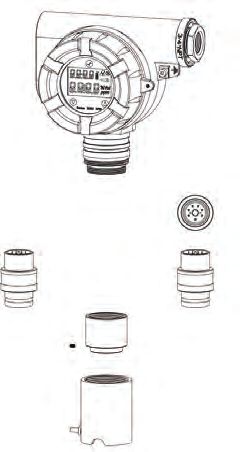
Table of Contents
    1 Mounting and Location of Detectors������������������������������������������������6
        1.1 Mounting the XNX Universal Transmitter�������������������������������6
    2 Wiring the XNX������������������������������������������������������������������������������������9
        2.1 General Wiring Considerations�����������������������������������������������9
             2.2 Distance Considerations for Installation����������������������������10
        2.3 POD Connections�������������������������������������������������������������������13
        2.4 4-20mA Output, Common Connections and Power���������������13
        2.5 Terminal Block Connections�������������������������������������������������15
        2.6 EC Personality Wiring������������������������������������������������������������16
             2.6.1 XNX Electrochemical (EC) Sensor Installation��������������18
        2.7 mV Personality Wiring�����������������������������������������������������������20
        2.8 IR Personality Wiring�������������������������������������������������������������24
             2.8.1 Connecting a Searchpoint Optima Plus or Searchline
                     Excel������������������������������������������������������������������������������25
             2.8.2 Connecting Generic mA Device�������������������������������������25
    3 Options����������������������������������������������������������������������������������������������29
        3.1 Local HART® Handheld����������������������������������������������������������29
        3.2 Relays��������������������������������������������������������������������������������������30
        3.3 Modbus®����������������������������������������������������������������������������������������������������������������������������������������������� 31
    4 Powering the XNX for the First Time�����������������������������������������������32
        4.1 XNX Units Configured for EC, mV, and IR (except Searchline
            Excel) �������������������������������������������������������������������������������������������� 32
        4.2 XNX IR Units Configured for Searchline Excel��������������������33
        4.3 Configuring the XNX Universal Transmitter�������������������������34
    5 The XNX Front Panel������������������������������������������������������������������������35
        5.1 Controls and Navigation��������������������������������������������������������35
        5.2 The General Status Screen����������������������������������������������������35
        5.3 Entering the Menu Structure�������������������������������������������������37
    6 Gas Calibration Menu����������������������������������������������������������������������38
        6.1 Calibration������������������������������������������������������������������������������38
             6.1.1 Calibration Procedure����������������������������������������������������38
             6.1.2 Zero and Span Calibration for XNX EC Sensors�����������41
             6.1.3 Zero and Span Calibration of XNX EC Hydrogen Sulfide (H2S)
                    Sensors������������������������������������������������������������������������������������������� 41
             6.1.4 XNX EC Sensor Operational Life�����������������������������������42
             6.1.5 Zero and Span Calibration for MPD Sensors����������������������������42
             6.1.6 Cross Calibration procedure for MPD-CB1��������������������44
             6.1.7 Calibrating the 705/705HT���������������������������������������������46
             6.1.8 Calibrating the Sensepoint/Sensepoint HT��������������������46
             6.1.9 Calibrating the Searchline Excel and Searchpoint Optima
                     Plus��������������������������������������������������������������������������������46
        6.2 Functional Gas Testing (Bump Test)�������������������������������������46
    7 XNX Electrochemical Sensor Data�������������������������������������������������47
4                                                                                     XNX Universal Transmitter Quick Start Guide
Table of Contents (cont’d)
     8 XNX Catalytic Bead and IR Replacement Sensor Cartridges�������48
     9 Warning Messages���������������������������������������������������������������������������48
     10 Fault Messages�������������������������������������������������������������������������������52
     11 Informational Messages����������������������������������������������������������������62

XNX Universal Transmitter Quick Start Guide                                                                5
1 Mounting and Location of Detectors

            Caution
    The location of the transmitters and sensors should be made in accordance with
    any relevant local and national legislation, standards or codes of practice. Always
    replace detectors with a detector of the same type. The detector should be mounted
    where the gas is most likely to be present. The following points should be noted
    when locating gas detectors.
    •    When locating detectors consider the possible damage caused by natural
         events e.g. rain or flooding.
    •    Consider ease of access for functional testing and servicing.
    •    Consider how escaping gas may behave due to natural or forced air
         currents.
    Note
        The placement of detectors should be determined following the advice
        of experts having specialist knowledge of gas dispersion, experts having
        knowledge of the process plant system and equipment involved, safety and
        engineering personnel. The agreement reached on the location of detectors
        should be recorded.
1.1 Mounting the XNX Universal Transmitter
The XNX Universal Transmitter can be mounted in a number of different methods
using the integral mounting tabs.
Using the mounting tabs, the XNX can be attached to:
    • flat wall surface
    • Unistrut®
With the optional Pipe Mount kit, the XNX can be mounted to pipe of diameter 2 to
6 in (50 to 150mm).
A ceiling mount bracket kit (1226A0358) is also available.
                                                Integral Mounting Lugs

        Figure 1. Integral Mounting Lugs and Optional Pipe and Ceiling Mounts

6                                             XNX Universal Transmitter Quick Start Guide
7.75" 4.48"
196.85 mm 113.8 mm
2.054"
6.00" 52.18mm
15.4 mm
5.6" 0.625"
124.24 mm 15.88mm
0.55"
14.35 mm
1.768"
44.90 mm
6.138"
158.75mm
1.768"
44.90 mm 3.176"
80.67 mm
1.67"
42.41 mm
1.2"
31.75mm 0.945"
24mm
Allow 11" 280mm
for Maint./Service
w/sun shield
152 mm
6"
XNX with
Searchpoint Optima Plus
4"
101.6mm
Allow
12"
305mm
For XNX with MPD or Local EC Sensor
Maintenance
Service
Figure 2. XNX Universal Transmitter Mounting Dimensions and Clearances
Warning
When the XNX is equipped with the optional Remote Mount Kit, the remote sensor
MUST be securely mounted to a fixed position. The Remote Sensor Kit is not intended
to be used as a hand-held detector.
XNX Universal Transmitter Quick Start Guide 7The XNX is configured with 5 cable/conduit entries built into the housing for wiring and
mounting sensors; Figure 3 provides the guidelines to proper installation of the XNX.
A Note
While relay wiring can use any
available cable/conduit entry in
E the XNX enclosure, do not use the
same cable/conduit entry for both
relay reset and relay signal lines to
avoid electrical noise.
*
D
* Limited access due to
B IS barrier if equipped with
electrochemical cell.
Option Position
C Local HART Option
®
B
MPD, 705 Series, Sensepoint Series C
Catalytic Bead Sensor C
Searchpoint Optima Plus A or E
Searchline Excel Typically C
Remote Sensor Connection (except EC ) Any remaining
Searchpoint Optima Plus - Remote Any remaining
Modbus® Any remaining
Relays Any remaining
Power Any remaining
Figure 3. XNX Universal Transmitter Cable/Conduit Entry Assignments
Integral Mounting Lugs
Figure 4. Integral Mounting Lugs and Optional Pipe and Ceiling Mounts
8 XNX Universal Transmitter Quick Start Guide2 Wiring the XNX
Personality circuit boards determine the XNX behavior based on the sensor type
attached to the XNX interface.
The table below defines the three XNX transmitter configurations and the sensors
each support.
XNX IR Personality XNX EC Personality
Searchpoint Optima Plus Local/
Searchline Excel XNX EC Sensor
Remote
Generic mA Sensors XNX EC Sensor Remote Mount Kit
XNX mV Personality
705 Local / Remote MPD Local (cat bead and IR) Sensepoint Local / Remote
705HT Local / Remote MPD Remote Sensepoint PPM Local/Remote
Sensepoint HT Remote
Caution
Before wiring the XNX, confirm the correct personality boards and options are
installed.
2.1 General Wiring Considerations
For proper operation of the XNX Universal Transmitter and Sensor Technologies,
consideration of wiring induced voltage drops, transient electrical noise and dissimilar
Earth ground potentials is imperative in the design and installation of the system.
Loading
Wiring for DC Power, 4-20mA Signal, remote wiring to sensors must be sized
sufficiently to provide sufficient voltages for the line length and the loads that will
be used.
Isolation
Isolating power and signal carrying conductors is recommended.
Circuit Protection
Supply circuits must provide over current protection. Class 2 power supplies are
required for 24 volt DC supply. Consider Inrush current in specifying any DC supply.
Power supply range is 16 to 32 VDC for EC and mV versions, 18 to 32 VDC for
Searchpoint Optima Plus and Searchline Excel and 16 to 32 VDC dependent on
the limitations of device for the generic 4-20mA input.
XNX Universal Transmitter Quick Start Guide 9Loads
The use of High Inrush or Inductive loads may affect the performance of the XNX.
For best reliability use resistive loads only.
2.2 Distance Considerations for Installation
Types of Installations
There are three basic types of installation: a single transmitter; multiple transmitters
connected to a single power source; and multiple transmitters connected in a “daisy-
chain” configuration.
Power Source Selection
The power requirements for different transmitter configurations are:
• XNX EC (Toxic): 6.2 watts
• XNX mV (Catalytic): 6.5 watts
• XNX IR with Searchpoint Optima Plus: 9.7 watts
• XNX IR with Searchline Excel: 13.2 watts
Wire Selection
The type of wire used for connections has an effect on the distance of the
installation. This is because some of the voltage is lost in the wire on the way to
the transmitter.
Distance Chart for Single Transmitter Distances
For installations that have dedicated wiring between the transmitter and the power
supply, use the following chart. These distances assume stranded wire is used.
OR
Class 2 Class 2
Power Supply Power Supply
Note
If multiple transmitters are using the same power supply, make sure the
power supply wattage rating is high enough to power all transmitters
simultaneously.
Single Transmitter Distances
18 AWG 16 AWG 14 AWG 12 AWG
[1.0 mm2] [1.5 mm2] [2.0 mm2] [3.5 mm2]
XNX mV or EC 1140 feet 1810 feet 2890 feet 4620 feet
With Sensor [347 meters] [551 meters] [880 meters] [1408 meters]
XNX IR with 660 feet 1060 feet 1690 feet 2690 feet
Searchpoint Optima Plus [201 meters] [323 meters] [515 meters] [820 meters]
XNX IR with 550 feet 890 feet 1410 feet 2260 feet
Searchline Excel [168 meters] [270 meters] [430 meters] [690 meters]
10 XNX Universal Transmitter Quick Start Guide“Daisy-Chained” Transmitter Distances
A few selected scenarios are presented here to provide a base to work from.
Transmitter 1 Transmitter 2 Transmitter 3 Transmitter 4 Transmitter 5
Class 2
Power Supply
“d” “d” “d” “d” “d”
1. Several transmitters equally spaced from themselves and the power source.
2 Transmitters - Distance “d”
18 AWG 16 AWG 14 AWG 12 AWG
[1.0 mm2] [1.5 mm2] [2.0 mm2] [3.5 mm2]
XNX mV or EC 380 feet 600 feet 960 feet 1540 feet
With Sensor [115 meters] [183 meters] [292 meters] [469 meters]
XNX IR with 220 feet 350 feet 560 feet 900 feet
Searchpoint Optima Plus [67 meters] [106 meters] [170 meters] [274 meters]
XNX IR with 185 feet 295 feet 470 feet 750 feet
Searchline Excel [56 meters] [90 meters] [143 meters] [229 meters]
3 Transmitters - Distance “d”
18 AWG 16 AWG 14 AWG 12 AWG
[1.0 mm2] [1.5 mm2] [2.0 mm2] [3.5 mm2]
XNX mV or EC 190 feet 300 feet 480 feet 770 feet
With Sensor [58 meters] [91 meters] [146 meters] [234 meters]
XNX IR with 110 feet 175 feet 280 feet 450 feet
Searchpoint Optima Plus [33 meters] [53 meters] [85 meters] [137 meters]
XNX IR with 90 feet 145 feet 235 feet 375 feet
Searchline Excel [27 meters] [44 meters] [71 meters] [114 meters]
4 Transmitters - Distance “d”
18 AWG 16 AWG 14 AWG 12 AWG
[1.0 mm2] [1.5 mm2] [2.0 mm2] [3.5 mm2]
XNX mV or EC 110 feet 180 feet 290 feet 460 feet
With Sensor [33 meters] [55 meters] [88 meters] [140 meters]
XNX IR with 65 feet 105 feet 165 feet 270 feet
Searchpoint Optima Plus [20 meters] [32 meters] [50 meters] [82 meters]
XNX IR with 55 feet 85 feet 140 feet 225 feet
Searchline Excel [17 meters] [26 meters] [43 meters] [68 meters]
5 Transmitters - Distance “d”
18 AWG 16 AWG 14 AWG 12 AWG
[1.0 mm2] [1.5 mm2] [2.0 mm2] [3.5 mm2]
XNX mV or EC 75 feet 120 feet 190 feet 300 feet
With Sensor [23 meters] [36 meters] [58 meters] [91 meters]
XNX IR with 45 feet 70 feet 110 feet 180 feet
Searchpoint Optima Plus [13 meters] [21 meters] [33 meters] [55 meters]
XNX IR with 35 feet 55 feet 90 feet 150 feet
Searchline Excel [11 meters] [17 meters] [27 meters] [46 meters]
XNX Universal Transmitter Quick Start Guide 112. Several transmitters installed in pairs with each pair equally spaced from
themselves and the power source. These distances assume the paired
transmitters are installed within 10 feet [3 meters] of each other.
Transmitters 1 and 2 Transmitters 3 and 4 Transmitters 5 and 6
Class 2
Power Supply
“d” “d” “d”
2 Transmitters - Distance “d”
18 AWG 16 AWG 14 AWG 12 AWG
[1.0 mm2] [1.5 mm2] [2.0 mm2] [3.5 mm2]
XNX mV or EC 485 feet 775 feet 1230 feet 1970 feet
With Sensor [147 meters] [235 meters] [292 meters] [600 meters]
XNX IR with 380 feet 600 feet 960 feet 1540 feet
Searchpoint Optima Plus [115 meters] [180 meters] [290 meters] [470 meters]
XNX IR with 280 feet 440 feet 700 feet 1130 feet
Searchline Excel [85 meters] [134 meters] [213 meters] [344 meters]
4 Transmitters - Distance “d”
18 AWG 16 AWG 14 AWG 12 AWG
[1.0 mm2] [1.5 mm2] [2.0 mm2] [3.5 mm2]
XNX mV or EC 190 feet 300 feet 480 feet 770 feet
With Sensor [58 meters] [91 meters] [146 meters] [234 meters]
XNX IR with 110 feet 175 feet 280 feet 450 feet
Searchpoint Optima Plus [33 meters] [53 meters] [85 meters] [137 meters]
XNX IR with 90 feet 145 feet 235 feet 375 feet
Searchline Excel [27 meters] [44 meters] [71 meters] [114 meters]
6 Transmitters - Distance “d”
18 AWG 16 AWG 14 AWG 12 AWG
[1.0 mm2] [1.5 mm2] [2.0 mm2] [3.5 mm2]
XNX mV or EC 95 feet 150 feet 240 feet 385 feet
With Sensor [33 meters] [45 meters] [73 meters] [117 meters]
XNX IR with 55 feet 85 feet 140 feet 225 feet
Searchpoint Optima Plus [17 meters] [26 meters] [42 meters] [68 meters]
XNX IR with 45 feet 70 feet 115 feet 185 feet
Searchline Excel [14 meters] [21 meters] [35 meters] [56 meters]
12 XNX Universal Transmitter Quick Start Guide2.3 POD Connections
The illustration in Figure 5 details the connections available on each of the terminal
blocks for each type of personality board.
E J1 - Remote HART® Connector Only
A
Personality
B
Boards
Boards
Option
F
C
Figure 5. XNX Personality Board
Terminal Block Legend
D
Table A Table B
Board Type Function S1 S2 Board Type Connection Function
EC Personality Source EC Personality Power, 4-20mA
4-20mA
mV Personality Sink Power, 4-20mA,
Output mV Personality
IR Personality Isolated TB1 Sensor
Power, 4-20mA,
IR Personality IR Power and
Signal
Table C Table D
Board Type Function S3 S4 Board Type Connection Function
IR 4-20mA Source 6 6 EC Personality J2 EC IS Barrier
IR Personality Input Sink 5 5 IR Personality TB2 Com A and B
Table E Table F
Board Type Connection Function Board Type Connection Function
Remote Reset
Relay TB4 Relay TB3 Relay Output
Connector
Bus Loop Data
Modbus® SW5 Terminators Modbus® TB3 Connection
2.4 4-20mA Output, Common Connections and Power
Setting 4-20mA operation; S1 & S2
The XNX Universal Transmitter allows the user to configure the 4-20mA output to Sink,
Source or Isolated mode operation via two programming switches on the POD. The
table below shows the S1 and S2 setting and corresponding output configuration.
S1 S2
Source Down Up
Sink Up Down
Isolated Down Down
XNX Universal Transmitter Quick Start Guide 13Power and 4-20mA connections are made at TB-1 and are identical for the EC , IR and
mV Personality Boards. For user convenience a second set of Terminals have been
provided to eliminate the need for a secondary junction box in multi node systems.
Controller XNX
+VE 1 1-1
+V
RL
Signal +mA
2 1-5
Current
Flow
-VE -V
3 1-3
XNX Sink Configuration
Figure 6. Sink wiring for XNX
Terminate cable screen at the detector or controller, not both.
Controller XNX
+VE +V
1 1-1
Signal -mA
2 1-6
RL Current
Flow
-VE -V
3 1-3
XNX Source Configuration
Figure 7. Source wiring for XNX
Controller XNX
+V1 +V
1-1
+V2 1-5
+mA
-V2 -mA
1-6
-V1 -V
1-3
XNX Isolated Configuration
Figure 8. Isolated wiring for XNX
14 XNX Universal Transmitter Quick Start GuideThe XNX Universal Transmitter power consumption is dependent on the sensor and
options for the specific configuration. The input voltage must be maintained at 18 to
32 volts DC for proper operation.
The table below defines the XNX typical and maximum power consumption based on
configuration:
Max
Configuration Inrush
Power
XNX EC 6.2 w2.6 EC Personality Wiring
Warning
When the XNX is equipped with the optional Remote Mount Kit, the remote sensor
MUST be securely mounted to a fixed position. The Remote Sensor Kit is not
intended to be used as a hand-held detector.
J1 - Local HART Connector
J1
1
LOCAL HART 2
20 mA 3
4
Operation
5
S1 S2 6
Source
Sink S1 S2
Isolated
+V 1-1 S1 and S2 - Signal Output
16-32 VDC
6.2W max.
1-2 Jumper Switch
-V 1-3
S1 S2
1-4
Source ▼ ▲
4-20mA
+mA 1-5
HART
Sink ▲ ▼
-mA 1-6 Isolated ▼ ▼
EC TB-1
Position EC
J2 - EC Barrier Connector
TB1
EC Barrier J2 1 +24
XNX EC TB-1
2
3 0v
4
Figure 10. XNX EC Personality Board Terminal Blocks and Jumper Switches and
Terminal Block Assignments
Caution
Be certain to dress the wires properly to ensure cabling does not contact switches
1-2 on the back of the POD.
Do not force the POD into the enclosure as it may indicate an interference condition
resulting in damage to the wiring, POD or switch settings.
16 XNX Universal Transmitter Quick Start GuideOptional Local HART
IS Barrier must
J1 HART
S1 S2
be connected to J1
1
2
Terminal Block 1
3
4
+ 5
- 6
J2 EC Barrier
EC IS Barrier must
be connected to J2
Local HART EC IS Barrier
IS Barrier
(optional)
HART
Adaptor
EC
Adaptor
Sensor Cartridge
Sensor Retainer
Sensor Cartridge Weatherproof Cap
Local Sensor Mounted to Transmitter
Sensor Retainer
Weatherproof Cap
Sensor Mounted to
Remote Sensor Kit
Figure 11. EC Personality Wiring
Note:
Reference Control Drawing 3000E3157 for install requirements on EC cells
and remote mounting.
XNX Universal Transmitter Quick Start Guide 172.6.1 XNX Electrochemical (EC) Sensor Installation
Caution
For biased sensors (e.g. Nitrogen Dioxide) remove the sensor stabilizer from the
bottom of the sensor prior to installation.
Using Figure 12 as a guide, follow the procedure below:
1. Check that the label on the new sensor is the correct gas type.
2. Unscrew the weatherproof cover, loosen the retainer locking screw with the
supplied hex key and unscrew the sensor retainer.
3. Plug in the new sensor taking care to align the sensor pins with the
connector.
4. Refit the sensor retainer, tighten the locking screw with the supplied hex
key and refit the weatherproof cover.
5. Countdown time of up to 180 seconds (dependent on sensor type) is
displayed.
6. Acknowledgement of the gas type will be required before proceeding. For
more information on setting gas type, see Gas Selection.
7. After the sensor is installed and the gas type is confirmed, the Range, alarm
levels and other important settings must be set; see Section 4.1 - Configuring
the XNX Universal Transmitter.
8. Once the XNX has been configured, calibrate the detector following the
procedures in Section 6.1 - Calibration.
Transmitter
New Sensor
3
Sensor Retainer &
Locking Screw
2 4
1 5
Weatherproof Cap
Figure 12. Installing Plug In Sensor
18 XNX Universal Transmitter Quick Start GuideXNX EC Sensor Remote Mounting Kit
The remote sensor mounting kit is used to remotely mount the sensor from the
transmitter. To remotely mount the sensor, follow the procedure below.
1. Unscrew the weatherproof cover, loosen the retainer locking screw and
unscrew the sensor retainer.
2. Remove the sensor by pulling without twisting.
3. Plug the remote sensor cable connector into the bottom of the transmitter.
4. Route the cable to the location where the remote sensor is to be mounted.
5. If necessary, cut the cable to the required length.
Caution
Take care not to cut the cable too short. Once cut, additional lengths of cable
cannot be added as this will invalidate the intrinsically safe certification. We also
recommend that a loop of cable is made at the junction box to allow slack for any
future re-termination.
The enclosure of the remotely mounted sensor contains aluminum. Care must
be taken to avoid ignition hazards due to impact or friction when installed in the
Zone 1 location.
All cable entry devices and blanking elements shall be certified in type of explosion
protection flameproof enclosure “Ex e”, suitable for the conditions of use and
correctly installed.
6. Mount the remote sensor junction box ensuring enough room below to fit
the sensor and weatherproof cover.
7. Attach the cable to the remote terminal box via the gland provided.
8. Make the wiring connections as shown below.
9. Fit the terminal box lid.
10. Plug the sensor into the socket at the bottom of the terminal box.
11. Fit the sensor retainer, tighten the locking screw and fit the weatherproof cover.
12. Calibrate the detector following the procedures in Section 6.1 - Calibration.
XNX Universal Transmitter Quick Start Guide 19Connections
Pin # Color
1 Yellow
2 Green
3 Blue
4 White
5 Red
6 Black
CAUTION
Take care not to cut the cable too short. Once cut, additional lengths of cable
cannot be added as this will invalidate the intrinsically safe certification. HA
also recommends that a loop of cable is made at the junction box to allow
Sensor Cartridge slack for any future re-termination.
The enclosure of the remotely mounted sensor contains aluminum. Care must
be taken to avoid ignition hazards due to impact or friction when installed in the
Zone 1 location.
Sensor Retainer
All cable entry devices and blanking elements shall be certified in type of
explosion protection flameproof enclosure “Ex e”, suitable for the conditions of
use and correctly installed.
Weatherproof Cap
Sensor Mounted to
Remote Sensor Kit
Figure 13. Installing Remote Sensor Mounting Kit
2.7 mV Personality Wiring
XNX Universal Transmitter with the mV personality Board allows interface to a number
of HA’s Multi Purpose Detector MPD and field proven 705 and Sensepoint devices.
Caution
• Check to ensure the XNX and mV Sensor has the appropriate approvals for your
installation prior to commissioning
• Check the mV Sensor you are installing has compatible threads - 3/4 NPT or M25.
Connections from the mV Sensor to the XNX are made via a single pluggable terminal
block allowing ease of installation and service. HA recommends an 8” (203mm)
service length for wiring be maintained. The Wire Colors for the connections for
each sensor type are shown in Figure 14.
Be sure wires for 4-20mA outputs are routed away from sources of noise such as
relay wires.
20 XNX Universal Transmitter Quick Start GuideNote
The black and red wires from the MPD are not used with the XNX mV Personality
Board. Ensure they are properly isolated from live connections. DO NOT CUT.
Caution
Be certain to dress the wires properly to ensure cabling does not contact switches
1-2 on the back of the POD.
Do not force the POD into the enclosure as it may indicate an interference condition
resulting in damage to the wiring, POD or switch settings.
J1 J1 - Local HART Option Connector
LOCAL HART
20 mA
Operation
S1 S2
Figure 14. XNX mV Personality Board
Source
Sink S1 S2
Terminal Blocks, Jumper Switches and
Isolated
+V 1-1
Wire Color Chart
16-32 VDC
6.5W max.
1-2 S1 and S2 - 20mA Output
-V 1-3 Jumper Switch
1-4 S1 S2
+mA 1-5 ▼ ▲
4-20mA MPD, 705
Source
HART Sensepoint
-mA 1-6 Sink ▲ ▼
Isolated ▼ ▼ 1
Sense 1-7 2
3
0v 1-8 4
5
6
Ref 1-9 7
8
9
mV TB-1
XNX mV TB-1
mV Sensor Type
Catalytic Bead MPD w/IR
705 Sensept Sensept IR 5%
MPD IR Flam
705HT Senspt HT PPM CO2 CH4
TB-1 Desc. Wire Color from Sensor
Pins 1-6 See Figure 5
7 Sense Brown Red Brown
8 0v White Green White
9 Ref Blue Blue Blue
Internal Ground
XNX Universal Transmitter Quick Start Guide 21Optional Local HART
S1 S2
IS Barrier must
be connected to J1
J1 HART
1
2
3
4
Terminal Block 1
+ 5
- 6
Sense 7
Com 8
Ref 9
Internal Ground Lug
Local HART
IS Barrier
(optional)
HART
Adaptor
Ground Wire from
Sensepoint PPM and HT
MPD
705
Sensepoint
Figure 15. mV Personality Wiring
22 XNX Universal Transmitter Quick Start GuidemV Remote Sensor Mounting
The sensor can be mounted remotely from the transmitter. To remotely mount the
sensor, follow the procedure below.
1. Unscrew the XNX’s weatherproof cover, loosen the retainer locking screw
with the supplied hex key.
2. Run conduit from one of the XNX’s available conduit entries to the location
of the remote terminal housing.
A Terminal Housing provides a mounting base for the sensor and contains
the associated electronic circuit. The installation wiring enters the Terminal
Housing via conduit.
Killark HKB-BC Box Adalet X1HFC3L Box Honeywell Analytics Box
00704-A-1755 00704-A-1756 00780-A-0100
Figure 16. Remote Terminal Housings
The distance between the XNX Transmitter and remote installation must comply
with the following to insure proper operation. Distances are dependent on sensor
types and the wire gauge used.
MPD CB1, 705
AWG Metric Wire Gauge Series.Sensepoint MPD IC1, IV1 & IF1 Sensors
Series Sensors
24 0.25 mm2 12m (47 ft.) 30m (97 ft.)
22 20m (65 ft.) 50m (162 ft.)
20 0.5 mm2 30m (97 ft.) 80m (260 ft.)
18 50m (162 ft.) 120m (390 ft.)*
16 1.0 mm2 80m (260 ft.)* 200m (650 ft.)*
* Frequency of Zero calibration may increase due to the changes in wire resistance from changing temperature
3. Wire the pluggable terminal block as shown in Figure 14 then plug the
connector into the back of the mV personality board.
4. Mount the remote sensor junction box ensuring enough room below to fit
the sensor and weatherproof cover.
5. Attach the conduit to the remote terminal box.
6. In the remote junction box, connect the wires from the XNX to the 3-way
terminal block provided in the terminal enclosure.
NOTE
The black and red wires from the MPD are not used with the XNX
mV Personality Board. Ensure they are properly isolated from live
connections. DO NOT CUT.
XNX Universal Transmitter Quick Start Guide 23Caution
The enclosure of the remotely mounted 705 HT sensor contains aluminum. Care must
be taken to avoid ignition hazards due to impact or friction when installed in the Zone
1 location.
All cable entry devices and blanking elements shall be certified in type of explosion
protection flameproof enclosure “Ex d” or “Ex e”, suitable for the conditions of use
and correctly installed
7. Attach and wire the sensor into the terminal box.
8. Fit the terminal box lid.
9. Fit the sensor retainer, tighten the locking screw and fit the weatherproof
cover (if required).
10. Calibrate the detector following the procedure is Section 3 - Calibration.
2.8 IR Personality Wiring
Gas concentrations are read by the XNX from the Searchpoint Optima Plus or
Searchline Excel 4-20mA output. A digital communication connection on TB2
provides an additional confirmation as well as diagnostic information.
Connections from the Searchpoint Optima Plus or Searchline Excel to the XNX
are made via two pluggable terminal blocks allowing ease of installation and
service see Figure 14. HA recommends an 8” (203mm) service length for wiring
be maintained.
Be sure wires for 4-20mA outputs are routed away from sources of noise such as
relay wires The Searchpoint Optima Plus or Searchline Excel can be supplied in
either Sink or Source mode operation and is typically labeled on the white wire
exiting the Searchpoint Optima Plus or Searchline Excel. Use the table below to set
S3 and S4 to the complimentary operating state of the equipment.
For more information see the Searchpoint Optima Plus Operating Instructions
(2104M0508) or the Searchline Excel Technical Manual (2104M0506).
Caution
Be certain to dress the wires properly to ensure cabling does not contact switches
1-4 on the back of the POD.
Do not force the POD into the enclosure as it may indicate an interference condition
resulting in damage to the wiring, POD or switch settings.
Warning
Setting of S3 and S4 while power is applied or improperly set prior to applying power
WILL PERMANENTLY DAMAGE the XNX. Both switches must be set in either Source
or Sink prior to applying power.
Do not adjust switch settings while power is applied to the XNX; permanent damage
WILL occur.
24 XNX Universal Transmitter Quick Start Guide2.8.1 Connecting a Searchpoint Optima Plus or Searchline
Excel
Connections from the Searchpoint Optima Plus or Searchline Excel to the XNX are
made via two pluggable terminal blocks allowing ease of installation and service
(see Figure 14). HA recommends an 8” service length for wiring be maintained.
The Searchpoint Optima Plus or Searchline Excel can be supplied in either Sink
or Source mode operation and is typically labeled on the white wire exiting the
Searchpoint Optima Plus or Searchline Excel. Use the table in Figure 14 to set S3
and S4 to the SAME output type that appears on the wire tag of the IR device.
Note:
A second, black-handled screwdriver is included for use on terminal blocks 2
and 4. This tool is smaller than the magnetic wand and is designed to fit into
the terminal connections on TB2 and TB4.
For more information see the Searchpoint Optima Plus Operating Instructions
(2104M0508) or the Searchline Excel Technical Manual (2104M0506).
Attaching the Searchpoint Optima Plus to the XNX Universal Transmitter
For M25 entries, insert the seal (P/N 1226-0410) into the proper cable/conduit
opening then thread the lock nut (P/N 1226-0409) onto the Optima to the end of
the threads then thread the optima body into the XNX until the seal compresses
and/or optima bottoms out, reverse until the semi-circular pattern of holes on the
front of the weather protection are on the bottom (see below) then tighten the lock
nut to the XNX body.
The 3/4” NPT entries do not require the seal and locknut, the form of the threads
provide positive locking and sealing.
Note:
When attaching the Searchpoint Optima Plus, be sure to coat the threads
with an anti-seize compound to prevent corrosion.
2.8.2 Connecting Generic mA Device
IR personality type provides for a Generic mA input under sensor type configuration.
The XNX can be used to convert the mA input to be read over HART protocol or
optional Modbus and set optional relays (if equipped). Additional configuration of
gas type and unit ID for reporting is required (see Gas Selection). For Generic mA
devices, input values below 3mA will generate Fault 155.
Use the following schematics to set S3 and S4 to the same output type that appears
on the wire tag of the mA device.
XNX Universal Transmitter Quick Start Guide 25XNX S3 and S4 should be in the UP position
Set mA Device and XNX to the same output type.
XNX mA Device
24V 7W Max
+IR +V
1-7
RL
Signal +mA
1-9
Current
Flow
-IR -V
1-8
XNX mA Input Sink Configuration
XNX S3 and S4 should be in the DOWN position
Set mA Device and XNX to the same output type.
XNX mA Device
+IR +V
1-7
Signal -mA
1-9
RL Current
Flow
-IR -V
1-8
XNX mA Input Source Configuration
Figure 17. Generic mA Device Sink/Source Schematic
26 XNX Universal Transmitter Quick Start GuideJ1 - Local HART Connector
J1
LOCAL HART
20 mA
Operation S1 and S2 - 20mA Output
S1 S2 Jumper Switch
Source
Sink S1 S2 S1 S2
Isolated
Source ▼ ▲
+V 1-1
13.2W max.
18-32 VDC HART Searchpoint
Sink ▲ ▼
1-2 ▼ ▼ 1
Isolated 2
-V 1-3 3
4
1-4 5
6
7
+mA 1-5 8
4-20mA Searchline
9
-mA 1-6 S3 and S4 - IR 20mA Input
+ Ir 1-7 Jumper Switch
- Ir 1-8 S3 S4
Sig 1-9 Source ▼ ▼
TB1
Ir TB-1 Sink ▲ ▲
TB-2 Ir Data
XNX IR TB-1 2
S3 S4 1
Source
Sink
TB2
TB1 TB2
From Searchpoint Optima Plus From Searchpoint Optima Plus
Desc. Desc.
Searchline Excel Searchline Excel
1 24v 1 Com B Orange
2 2 Com A Blue
3 Gnd See Common Connections
4 Section 2.2.3 XNX
5 20mA + From Searchpoint Optima Plus
Desc.
Searchline Excel
6 20mA -
Earth Green/Yellow
7 24v Red
8 0v Black
9 Sig White
Figure 18. XNX IR Personality Board Terminal Blocks, Jumper Switches and
Wiring Guide
Searchline Excel and Searchpoint Optima Plus Remote Installation
Junction Boxes are available for the Searchline Excel and Searchpoint Optima
Plus to facilitate remote mounting from the XNX Universal Transmitter. Junction
boxes are available for installations requiring UL/CSA or ATEX approvals. Consult
the Searchline Excel Technical Handbook (2104M0506) or Searchpoint Optima
Plus Operating Instructions (2104M0508) for specifics on remote installations
or contact your Honeywell Analytics representative for more information.
XNX Universal Transmitter Quick Start Guide 27S1 S2
Optional Local HART
IS Barrier must be
J1 HART
connected to J1
1
2
3
4
Terminal Block 1
5
+ 6
+24 7
Gnd 8
Sig 9
S3 S4
A 1
B 2
Terminal Block 2
IR Data
Searchpoint
Optima Plus
Local HART
IS Barrier
(optional)
HART
Adaptor
Figure 19. IR Personality Wiring - Searchpoint Optima Plus
Optional Local HART
J1 HART
S1 S2
IS Barrier must be
1 connected to J1
2
3
4
Terminal Block 1
5
+ 6
+24 7
Gnd 8
Sig 9
S3 S4
A 1
B 2
Terminal Block 2
IR Data
Local HART
IS Barrier
(optional)
HART
Adaptor
Searchline Excel
Figure 20. IR Personality Wiring - Searchline Excel
28 XNX Universal Transmitter Quick Start Guide3 Options
3.1 Local HART® Handheld
Available with any sensor technology or option, this option provides an external
access to the HART® interface in the XNX. An IS barrier inside the XNX allows the
user to attach an external hand-held interrogator for programming and configuration.
The external interface is installed in the lower left cable/conduit entry of the XNX
and is intrinsically safe (IS).
Intrinsically Safe Barrier
for HART Interface
HART Handheld Interface
Connector w/Protective Cap
Figure 21. XNX Universal Transmitter with HART® Interface IS Barrier installed
HART® devices can operate in one of two configurations - point-to-point or
multidrop.
Point-to-Point Mode
In point-to-point mode, the 4–20 mA signal is used to communicate one process
variable, while additional process variables, configuration parameters, and other
device data are transferred digitally via HART® protocol. The 4–20 mA analog signal
is not affected by the HART® signal.
Multidrop Mode
The multidrop mode of operation requires only a single pair of wires and, if applicable,
safety barriers and an auxiliary power supply for up to 8 field devices.
Note:
Use multidrop connection for supervisory control installations that are
widely spaced, such as pipelines, custody transfer stations, and tank
farms.
The minimum conductor size is 0.51mm diameter (#24 AWG) for cable runs less
than 1,524m (5,000 ft) and 0.81mm diameter (#20 AWG) for longer distances.
Cable Length
Most installations are well within the 3,000m (10,000 ft) theoretical limit for HART®
communication. However, the electrical characteristics of the cable (mostly
capacitance) and the combination of connected devices can affect the maximum
allowable cable length of a HART® network. The table in Figure 22 shows the affect
of cable capacitance and the number of network devices on cable length. The table
is based on typical installations of HART® devices in non-IS environments, i.e. no
miscellaneous series impedance.
XNX Universal Transmitter Quick Start Guide 29Cable Capacitance – pf/ft (pf/m)
Cable Length – feet (meters)
Number of Network 20 pf/ft 30 pf/ft 50 pf/ft 70 pf/ft
Devices (65 pf/m) (95 pf/m) (160 pf/m) (225 pf/m)
9,000 ft 6,500 ft 4,200 ft 3,200 ft
1
(2,769 m) (2,000 m) (1,292 m) (985 m)
8,000 ft 5,900 ft 3,700 ft 2,900 ft
5
(2,462 m) (1,815 m) (1,138 m) (892 m)
7,000 ft 5,200 ft 3,300 ft 2,500 ft
10
(2,154 m) (1,600 m) (1,015 m) 769 m)
6,000 ft 4,600 ft 2,900 ft 2,300 ft
15
(1,846 m) (1,415 m) (892 m) (708 m)
Figure 22. Allowable Cable Lengths for 1 mm (#18 AWG) Shielded Twisted Pair
3.2 Relays
The relay option (XNX-Relay) provides 3 form “C” SPCO contacts for alarm and fault
indication. TB4 is provided as a connection to a user installed momentary switch
to silence alarms remotely.
Note:
This option is not available with the Modbus® option.
Wiring for the relays is through an available cable/conduit entry to a pluggable terminal
block. See Figure 4 for the terminal block legend.
Note:
A second, black-handled screwdriver is included for use on terminal blocks 2
and 4. This tool is smaller than the magnetic wand and is designed to fit into
the terminal connections on TB4.
Relay
9
TB4
8
7
6
TB3
5
Remote
Reset SW
4
3 1 NC
2
1
Relay Ratings
250VAC 5A
2 C
24VDC 5A
3-1 NC
3 NO
Level 2 Level 1
3-2 C TB3 4 NC
3-3 NO
3-4 NC
5 C
3-5 C 6 NO
3-6 NO
3-7 NC
2
1
7 NC
Fault
3-8 C 8 C
3-9 NO
TB-3 RELAY TB4 9 NO
Warning: Power
externally supplied.
TB4
TB3 Relay Connections
Disconnect at source
prior to servicing. Warning: Power externally
supplied, disconnect at source
1 1
2
prior to servicing
Relay Contact Ratings:
250 VAC 5 amps
2
24 VDC 5 amps
Figure 23. XNX Relay Option Board Terminal Blocks
30 XNX Universal Transmitter Quick Start Guide3.3 Modbus®
Modbus® connections to the XNX are made through a pluggable terminal block on
the Modbus® interface circuit board. A loop termination point (SW5) is included on
the Modbus® interface board to provide termination of the Modbus® loop.
Terminals 3-1 through 3-4 are provided to facilitate bus
wiring; there is no internal connection to other XNX
circuitry. Terminal 3-1 is connected internally to 3-2.
S5 EOL Term Similarly, terminal 3-3 is connected to 3-4
RT =120
Out
In
Modbus®
TB-3 Modbus
TB3
3-1 + SW5 - Loop Termination
3-2 + 1 +
3-3 -
10 2 +
3-4 - 9
8
3-5 A 7
6
3 -
5
3-6 A 4
3
2
4 -
3-7 B 1
3-8 B 5 A
3-9 S 6 A
3-10 S
Use shorting jumper 7 B
supplied to maintain
connection during TB3 Modbus Connections
8 B
service
Use Jumper 9 S
to maintain
connection
during service 10 S
Figure 24. XNX Modbus® Option Board Terminal Block and Jumper Switch
XNX Universal Transmitter Quick Start Guide 314 Powering the XNX for the First Time
4.1 XNX Units Configured for EC, mV, and IR (except Searchline
Excel)
After mounting and wiring the XNX, the plug in sensor should be fitted (if equipped) and
the installation visually and electrically tested as below.
WARNING
Prior to carrying out any work, ensure local and site procedures are followed.
Ensure that the associated control panel is inhibited so as to prevent false alarms.
Minimum and maximum controller alarm levels should not be set at less than 10%
or greater than 90% of the full scale range of the detector. CSA and FM agency
limits are 60% LEL or 0.6mg/m3.
Caution
The following procedure should be followed carefully and only performed by
suitably trained personnel
1. Check that the transmitter is wired correctly according to this manual and
the associated control equipment manual.
2. If equipped, unscrew the weatherproof cover, loosen the sensor retainer
locking screw and unscrew the retainer.
3. Plug in the sensor cartridge taking care to align the sensor pins with the
connector holes in the PCB.
Caution
For toxic sensors, remove the shorting clip from the bottom of the sensor prior to
installation. For O2 sensor, there is no shorting clip provided.
4. Refit the sensor retainer, tighten the locking screw and refit the weatherproof
cover.
Note:
Before replacing the cover on the transmitter housing, coat the threads with
anti-seize compound to prevent corrosion buildup.
Also inspect the cover o-ring for cracking or any other defect that might
compromise the integrity of the seal. If it is damaged, replace with the o-ring
supplied in the accessory kit.
5. Apply power to the XNX which will in turn provide power to the detector.
6. The detector output will be forced to 3mA (default fault/inhibit).
7. The XNX display will enter a start up routine displaying the initialization
screen, then the transmitter loads its operating system, data from the
sensor and checks if it is the same type transmitter and sensor software
version numbers, gas type, the detection range and span calibration gas
level, estimated time to next calibration due, and self test result. The boot-up
procedure takes approximately 45 seconds.
32 XNX Universal Transmitter Quick Start GuideFigure 25. XNX Initialization and General Status Screens
Note:
In the final stages of boot-up, warnings and faults may be observed until
the user performs the proper configuration, calibration, and reset activities
described in the following sections. See Section 10 for descriptions of
warnings and faults.
8. Once the General Status screen appears, the transmitter and detector are
in normal ‘monitoring’ mode.
Note:
Calibration of sensors attached to the XNX is mandatory before the detector
can be used for gas monitoring. Refer to Section 6.1 - Calibration for the
proper procedure.
For EC and mV personalities, be sure to perform Accept New Sensor Type
before calibrating the sensor.
4.2 XNX IR Units Configured for Searchline Excel
When powering the XNX fitted to the Searchline Excel, the following procedure must
be followed to assure proper installation.
Caution
The following procedure should be followed carefully and only performed by
suitably trained personnel
1. Check that the transmitter is wired correctly according to this manual and
the associated control equipment manual.
2. Apply power to the XNX which will in turn provide power to the detector.
3. The detector output will be forced to 3mA (default fault/inhibit).
4. The XNX display will enter a start up routine displaying the initialization
screen, then the transmitter loads its operating system, data from the
sensor and checks if it is the same type transmitter and sensor software
version numbers, gas type, the detection range and span calibration gas
level, estimated time to next calibration due, and self test result. The boot-up
procedure takes approximately 45 seconds.
Figure 26. XNX Initialization and General Status Screens
XNX Universal Transmitter Quick Start Guide 33Note:
In the final stages of boot-up, warnings and faults may be observed until
the user performs the proper configuration, calibration, and reset activities
described in the following sections. See Section 10 for descriptions of
warnings and faults.
5. When the XNX completes boot-up, perform a Soft Reset on the Excel from
the Calibration Menu.
6. When the reset is complete, Set Date & Time.
7. Set the Path Length for the application, then align the transmitter and
receiver with Align Excel.
8. Once the alignment is complete, a Zero Calibration must be performed on
the Excel to complete the commissioning process. (See the Searchline Excel
Technical Manual for calibration information P/N 2104M0506).
9. Reset any faults displayed on the XNX display. The XNX and Excel are
now ready to monitor.
34 XNX Universal Transmitter Quick Start Guide4.3 Configuring the XNX Universal Transmitter
The XNX Universal Transmitter can be configured via the front panel by using the
menus available in the Configure Menu. For information on accessing and navigating
the menus, see Section 5.1 - Controls and Navigation.
The XNX is shipped with the following settings:
Display Language English
Date Format mm/dd/yy
Time Format HH:MM
mA Sensor Type (w/IR Personality) Searchpoint Optima Plus
mV Sensor Type (w/mV personality) MPD-IC1 (%Vol)
Alarm Levels Sensor Cartridge Dependent
Latching/Non-Latching Alarms Alarm: Latching
Fault: Non-Latching
Display Units PPM, %VOL or %LEL
(dependent on personality and sensor choice)
4-20 mA Levels Inhibit: 2.0 mA
Warning: 3.0 mA
Overrange: 21.0 mA
Calibration Interval 180 Days (HA recommends 30 day interval)
Unit ID XNX #nnnnnnnn
Relay Settings Alarm Normally De-Energized
Fieldbus Settings
HART® Address: 0
Mode: Point-To-Point
Modbus® Address: 5
(if installed) Baud Rate: 19200
Level 1 Password Access 0000
Level 2 Password Access 0000
Easy Reset Enabled Yes
XNX Universal Transmitter Quick Start Guide 355 The XNX Front Panel
The XNX uses magnetic switches to enable non intrusive operation. To activate a
magnetic switch, hold the factory-supplied magnet up to the glass window and swipe
the magnet directly over the shaded area.
Power LED
Alarm LED
(Green)
(Red) Fault LED
(Yellow)
Alarm Power Fault
Escape Enter / Accept
- XNX +
Switch Actuation
Universal Transmitter Visual Indicator
Move Left Move Right
Decrement Value Increment Value
Figure 27. The XNX Front Panel Display
5.1 Controls and Navigation
✓ The Enter/Accept key is used to access menus, accept changes
Enter / Accept and to respond “YES” to system prompts
✖ Use Escape key to return to previous menus or to answer “NO”
Escape / Back to system prompts
Use the Left / Decrement arrow to move through menu options or
Move Left / Decrement Value decrement values when entering text or numbers
Use the Right / Increment arrow to move through menu options or
Move Right / Increment Value Increment values when entering text or numbers
5.2 The General Status Screen
Figure 28. The General Status Screen
The General Status Screen provides a visual indication of the status of the XNX.
Warnings, faults, alarm levels and current concentration levels are displayed
continuously.
36 XNX Universal Transmitter Quick Start GuideCurrent Concentration Level
(Numeric)
Status Indicator
Concentration Units
Full Scale
Current Concentration Level
(Bar Graph) Alarm 2 Set Point
Alarm 1 Set Point
Figure 29. General Status Screen - Normal Operating Mode
The Normal Operating Mode icon gives visual indication of proper operation. When
a warning is triggered, the Warning icon appears and information is displayed
on the General Status Screen.
Warning Icon Warning Code
Figure 30. General Status Warning Detail
If the fault icon is displayed, a fault condition has been triggered and the display will
alternate the display of the target gas concentration and the fault code).
Fault Icon Fault Code
Figure 31. General Status Fault Detail
When an alarm icon is displayed, the target gas concentration exceeds one or
both preset alarm levels, the General Status Screen displays the gas concentration
and alarm level exceeded.
Alarm Icon Alarm Level Triggered
Target Gas
Concentration
Figure 32. General Status Alarm Detail
In an overrange condition, the alarm icon will display but the target gas concentration bar graph
and alarm setpoints will flash, see illustration below.
Alarm Level Triggered
Full Scale
Concentration
Concentration Bar, Alarm Setpoints Flash
Figure 33. General Status Overrange Detail
In addition to the graphic Alarm, Fault and Warning indicators, the LEDs on the front
panel will flash in a pattern based on the condition:
XNX Universal Transmitter Quick Start Guide 37LED
Condition
Red Green Yellow
Alarm 1 Solid
Alarm 2 Flashing
Warning Solid
Fault Flashing
Health Flashing
5.3 Entering the Menu Structure
Swiping the magnet over the magnetic switch ✓ or ✖ gives the user access to the
XNX to reset faults and/or alarms, display current settings or make adjustments to
the device.
NOTE:
If the Reset option is set to Lock, users will not have access to reset alarms
and faults. For more information on Security Settings for the XNX, see XNX
Universal Transmitter Technical Manual.
From the General Status menu, if the ✖
or ‘escape’ magnetic switch is swiped, the
Alarm Reset Screen activates. This allows
any user to silence alarms and reset faults
Figure 34. Alarm Reset Screen generated by the XNX.
Using the ✓ switch resets all alarms and faults and returns to the General Status
Screen, choosing ‘X’ will return to the General Status Screen without resetting the
alarms and faults.
Using the ✖ switch will return the user to the
General Status Menu. If the user selects ✓
from the General Status menu, it will activate
the passcode screen.
Figure 35. The Passcode Screen
There are two levels that control access based upon the security level of the user.
The passcodes for both levels are set at “0000” from the factory.
Level 1 Routine Maintenance Level 2 Technician and Password Admin
Warning
The factory-set passcodes must be reset to prevent unauthorized access to the
XNX menus (see the XNX Universal Transmitter Technical Manual).
Once the Passcode Screen is displayed, the first passcode digit is highlighted. Use
the switches to increment or decrement through the values. Once the correct
value is displayed for the first digit, ✓ accepts the value and moves to the next digit
or ✖ will move to the previous digit of the passcode.
38 XNX Universal Transmitter Quick Start Guide✓
Figure 36. Entering the Passcode
Repeat for each of the remaining digits in the passcode. If the passcode is not
entered correctly, the Invalid Passcode screen is displayed and the user is returned
to the General Status screen.
6 Gas Calibration Menu
The Gas Calibration menu is used for Zero and Span calibration as well as functional
gas testing (bump test). The Gas Calibration menu is accessed from the main
menu screen.
✓
Figure 37. Gas Calibration Menu
Gas Calibration Calibrate mA Output
Bump Test Soft Reset
Align Excel
6.1 Calibration
Caution
The calibration procedure should only be performed by qualified personnel.
Note:
Honeywell Analytics recommends that the maximum calibration interval
be 30 days or in accordance with customer site procedures to assure the
highest level of safety. Correct operation of each sensor/detector should be
confirmed with test gas of known concentration before each use.
See Section 7 - XNX Electrochemical Sensor Data for Calibration Gas
specifications.
6.1.1 Calibration Procedure
Note:
Follow the specific procedure outlined in the Operating Manual for each
sensing device.
1. If using compressed gas cylinder, attach the calibration gas flow housing
onto the bottom of the sensor and apply the gas.
2. Access the calibration mode.
XNX Universal Transmitter Quick Start Guide 39Figure 38. Gas Calibration Menu
NOTE:
The Gas Calibration menu is for both Zero and Span Calibration.
Zero Calibration
Sensor Reading
at Current Settings
Figure 39. Zero Calibration Screen
Select ✓ then apply the zero gas and as the sensor
detects the gas and the concentration is increasing,
the values displayed will reflect the changing
concentration. Selecting ✖ will return to the Gas
Figure 40. Zero Calibration Calibration menu.
in Progress
3. If the Zero Calibration is successful, the XNX Universal Transmitter will
display the Zero Passed screen.
Figure 41. Zero Calibration Passed
Span Calibration
NOTE:
If a Span Calibration is not required, select the ✖ to skip the Span Calibration
and return to the Calibration menu.
4. When the Zero Calibration is complete or it is skipped, the Span
Concentration screen appears to indicate the concentration value of the
gas used for calibration.
Figure 42. Span Gas Concentration Screen
5. Select ✓ to choose the first digit and use the switches to increment or
decrement the values; ✓ accepts the new value and move to the next digit.
Continue until all 3 digits have been selected.
40 XNX Universal Transmitter Quick Start GuideSensor Reading Calibration Gas
at Current Settings Concentration
Figure 43. Span Calibration Screen
6. Select ✓ then apply the target gas and as the sensor detects the gas and
the concentration is increasing, the sensor reading values in the display will
change to reflect the changing concentration.
7. When the concentration values stabilize, the gas concentration as read by
the installed sensor is stable. At this time, the gas readings are taken by the
sensor. The Span Calibration process also determines whether the sensor
is within the proper range to accurately detect the target gas.
8. When the sensor has completed the calibration and the span algorithms have
determined that it is within range, the Span Passed screen will appear.
If the calibration is not successful, the Span Failed screen will display. Selecting ✓
will return to the Span Concentration screen to begin the span calibration again. ✖
will exit Span Calibration and return to the Main Calibrate screen.
Arrow indicates Selecting ‘✔’ returns to
gas values too low the Span Concentration
screen
Figure 44. Span Calibration Failed
Once the Zero and Span calibrations are completed successfully, the XNX will exit
the calibration procedure. Before returning to the Gas Calibration menu however,
the user will be prompted to Exit and turn alarm and fault inhibit off, Exit and leave
the XNX in inhibit mode, or do not exit.
Warning
While XNX is in Inhibit Mode, alarms are silenced. This will prevent an actual gas
event from being reported. Inhibit Mode must be reset after testing or maintenance
activities.
XNX Universal Transmitter Quick Start Guide 41You can also read