FlashPro Express User Guide - AWS
←
→
Page content transcription
If your browser does not render page correctly, please read the page content below
FlashPro Express User Guide

Introduction
FlashPro Express is Microchip’s programming software tool designed from the ground up to address secured
programming assurance in production programming house environments. FlashPro Express software supports
         ®                            ®         ®             ™
PolarFire , PolarFire SoC, SmartFusion 2, IGLOO 2, and RTG4 in Windows and Linux OS environments, using the
FlashPro Programmer hardware.
You can install FlashPro Express two ways:
                              ®
  •   Integrated with Libero . FlashPro Express installs automatically when Libero is installed. FlashPro Express is
      used by Libero to perform the programming tasks for PolarFire, PolarFire SoC, SmartFusion2, IGLOO2, and
      RTG4, as part of the design flow.
  •   Stand-alone. FlashPro Express is also available as a stand-alone installation. This installation method is
      primarily used for production programming or lab programming on machines that do not require a full version of
      Libero.
For more information about FlashPro Express, see the Microchip website.

© 2021 Microchip Technology Inc.                         User Guide                               DS50003089B-page 1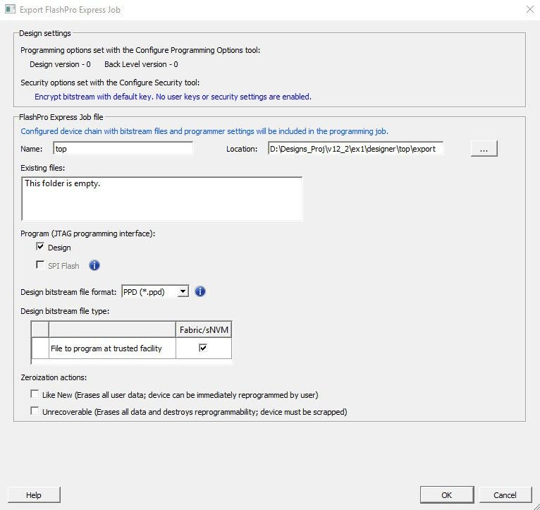
Table of Contents
Introduction.....................................................................................................................................................1

1.    Overview................................................................................................................................................. 4
      1.1.       FlashPro Hardware Programmers................................................................................................4
      1.2.       Secure Job Programming.............................................................................................................4
      1.3.       Migrating FlashPro Projects to FlashPro Express........................................................................4

2.    Installing FlashPro Express Software and Hardware..............................................................................6

3.    Supported Device Families..................................................................................................................... 7

4.    Getting Started........................................................................................................................................ 8
      4.1.       Starting FlashPro Express............................................................................................................8
      4.2.       FlashPro Express Interface.......................................................................................................... 8
      4.3.       Creating a Job Project from a FlashPro Express Job................................................................ 10
      4.4.       Opening a Job Project................................................................................................................ 11
      4.5.       Saving a Job Project.................................................................................................................. 12
      4.6.       Programming Tutorials............................................................................................................... 12

5.    Programming Connectivity and Interface.............................................................................................. 17

6.    Programmer Settings and Operations...................................................................................................19
      6.1.       Introduction.................................................................................................................................19
      6.2.       Programmer Settings................................................................................................................. 19
      6.3.       Ping Programmers..................................................................................................................... 21
      6.4.       Performing a Self-Test................................................................................................................21
      6.5.       Scanning and Checking a Chain................................................................................................ 21
      6.6.       Enabling and Disabling Programmers........................................................................................21
      6.7.       Renaming a Programmer........................................................................................................... 21
      6.8.       Removing a Programmer........................................................................................................... 21
      6.9.       Selecting and Running an Action............................................................................................... 21

7.    Chain Programming.............................................................................................................................. 23
      7.1.       Chain Order................................................................................................................................23
      7.2.       Multiple Device Chain Programming.......................................................................................... 23

8.    FlashPro Express Modes...................................................................................................................... 24

9.    TCL Commands.................................................................................................................................... 28
      9.1.       About Tcl Commands................................................................................................................. 28
      9.2.       Executing a Tcl Script File in FlashPro Express......................................................................... 28
      9.3.       Running Tcl Scripts from the Command Line............................................................................. 28
      9.4.       Exporting Tcl Scripts from FlashPro Express............................................................................. 29

10. Troubleshooting.....................................................................................................................................30
      10.1. PolarFire Exit Codes.................................................................................................................. 30
      10.2. RTG4 Exit Codes....................................................................................................................... 34
      10.3. SmartFusion2 and IGLOO2 Exit Codes..................................................................................... 38

© 2021 Microchip Technology Inc.                                                     User Guide                                                      DS50003089B-page 2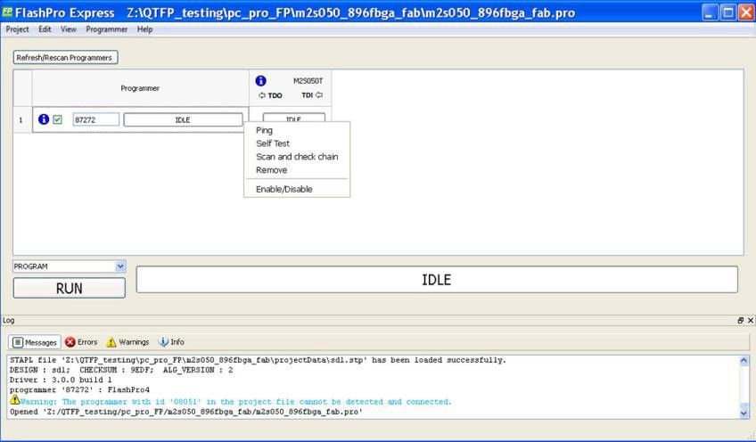
11. SmartDebug.......................................................................................................................................... 45

12. Electrical Parameters............................................................................................................................ 46
      12.1. DC Characteristics for FlashPro6...............................................................................................46
      12.2. DC Characteristics for FlashPro5/4/3/3X................................................................................... 47

13. Electrical Specifications........................................................................................................................ 49
      13.1.     FlashPro6................................................................................................................................... 49
      13.2.     FlashPro5................................................................................................................................... 49
      13.3.     FlashPro4................................................................................................................................... 50
      13.4.     FlashPro3................................................................................................................................... 51
      13.5.     JTAG Switching Characteristics................................................................................................. 52

14. FlashPro Express Reference................................................................................................................ 54
      14.1.     FlashPro Express Start Page..................................................................................................... 54
      14.2.     FlashPro Express Project Menu.................................................................................................54
      14.3.     FlashPro Express Edit Menu......................................................................................................54
      14.4.     FlashPro Express View Menu.................................................................................................... 54
      14.5.     FlashPro Express Tools Menu....................................................................................................55
      14.6.     FlashPro Express Help Menu.....................................................................................................55
      14.7.     FlashPro Express Log Window and Status Bar......................................................................... 55

15. Appendix A: Sample Programming and SmartDebug Times Using FlashPro5 and FlashPro6............ 56

16. Appendix B: Regulatory and Compliance Information.......................................................................... 58

17. Revision History.................................................................................................................................... 59

18. Microchip FPGA Technical Support...................................................................................................... 60
      18.1.     Customer Service.......................................................................................................................60
      18.2.     Customer Technical Support...................................................................................................... 60
      18.3.     Website...................................................................................................................................... 60
      18.4.     Outside the U.S.......................................................................................................................... 60

The Microchip Website.................................................................................................................................61

Product Change Notification Service............................................................................................................61

Customer Support........................................................................................................................................ 61

Microchip Devices Code Protection Feature................................................................................................ 61

Legal Notice................................................................................................................................................. 62

Trademarks.................................................................................................................................................. 62

Quality Management System....................................................................................................................... 63

Worldwide Sales and Service.......................................................................................................................64

© 2021 Microchip Technology Inc.                                                    User Guide                                                     DS50003089B-page 3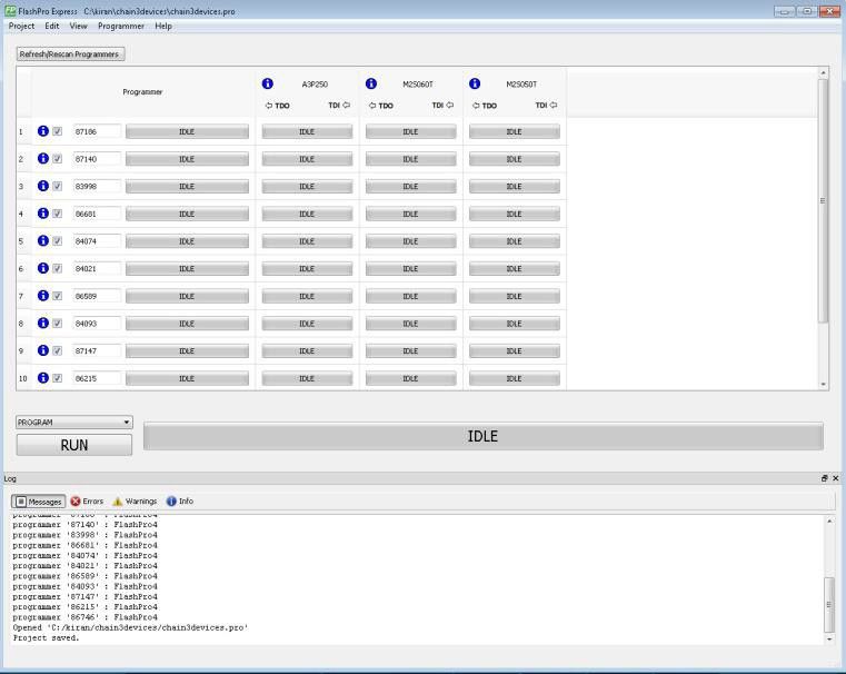
Overview

1.    Overview
      This section provides an overview of FlashPro Express.

1.1   FlashPro Hardware Programmers
      The FlashPro series of hardware programmers consists of:
       • FlashPro3/X
       • FlashPro4
       • FlashPro5
       • FlashPro6
      All FlashPro series hardware programmers save board space because a single JTAG chain can be used for all JTAG
      devices. In-system programming using the JTAG port adds the flexibility of field upgrades or post-assembly
      production-line characterization. Production costs are reduced significantly as a result of elimination of expensive
      sockets on the board.
      Note: FlashPro5 and FlashPro6 support programming though a device SPI Slave port.
      For more information, visit the Microchip website.

1.2   Secure Job Programming
      Job programming is the concept of using a single file to program a Microchip device or chain of Microchip devices
      using encrypted bitstreams.
      The single job file contains all of the information necessary to setup FlashPro Express as well as the encrypted
      bitstream images for the devices in the job. After a job file is created, it can be passed securely to production
      programming houses or contract engineering facilities to load the Microchip images during manufacturing. Job
      projects can be exported from Libero and imported into stand-alone FlashPro Express, providing a clean delineation
      between design flow and production programming.

1.3   Migrating FlashPro Projects to FlashPro Express
      Existing FlashPro projects (*.pro) files are called Job Project files in FlashPro Express. These Job Projects can be
      opened with FlashPro Express to take advantage of Linux programming support and the simplified tool targeted for
      operators in a production floor environment.
      Note: FlashPro projects that were created in single mode are not supported by this tool. Microchip recommends that
      you convert these projects to chain mode projects.
      To convert the project to a chain project:
        1.   Open the FlashPro project (*.pro) in FlashPro.
        2.   Locate the loaded STAPL file by one of two methods:
             The log prints STAPL file ‘’ has been loaded successfully.  is the location of the
             STAPL file loaded.
             Figure 1-1. Sample Log Message

      In the Single Device Configuration window, the field STAPL_FILE_NAME shows the location of the STAPL file
      loaded.

      © 2021 Microchip Technology Inc.                         User Guide                               DS50003089B-page 4
Overview

Figure 1-2. Location of STAPL File

  1.   Switch the project to chain mode using one of the two methods:

         – Press the chain button from the toolbar:
         – From the Tools menu, select Mode > Chain Programming.
  2.   Load the STAPL file in chain mode by adding a Microchip device in the chain.
       2.1.     From the File menu, select Configuration > Add Microchip Devices from Files.
       2.2.     Browse to the location of the STAPL file and click Open.
  3.   To save the project, from the File menu, select Save Project.
You can now open the project using FlashPro Express.
When moving FlashPro project (*.pro) files to another machine, Microchip recommends that you archive the entire
project folder, copy it to the new machine, extract it locally, and then load the job project within FlashPro Express.
FlashPro Express opens a job project only when a programmer is connected to the machine, at least one Microchip
device has programmed enabled, and all enabled Microchip devices have a bitstream file loaded.

© 2021 Microchip Technology Inc.                         User Guide                                 DS50003089B-page 5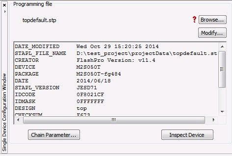
Installing FlashPro Express Software and Hardware

2.   Installing FlashPro Express Software and Hardware
     For information about installing the FlashPro Express hardware and software, see the Microchip website.

     © 2021 Microchip Technology Inc.                       User Guide                               DS50003089B-page 6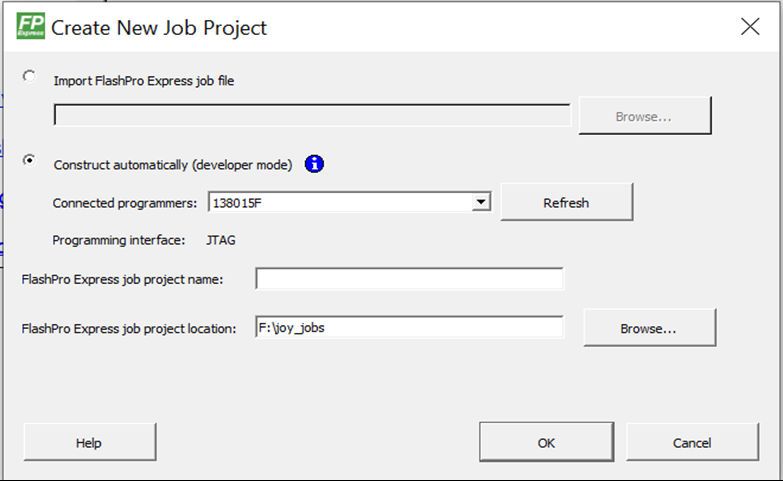
Supported Device Families

3.   Supported Device Families
     The following table lists the device families and their derivatives that FlashPro Express can program directly through
     Libero or by exporting a FlashPro Express job.
     Table 3-1. Product Families and Derivatives Directly Supported by FlashPro Express

      Device Family                                                 Description
      PolarFire            Lowest power, cost optimized mid-range solution.

      PolarFire SoC        Lowest power, multi-core RISC-V SoC FPGA.

      SmartFusion2         Addresses fundamental requirements for advanced security, high reliability, and low power in
                           critical industrial, military, aviation, communications, and medical applications.

      IGLOO2               Low-power mixed-signal programmable solution.

      RTG4                 Radiation-tolerant programmable solution.

     © 2021 Microchip Technology Inc.                         User Guide                                 DS50003089B-page 7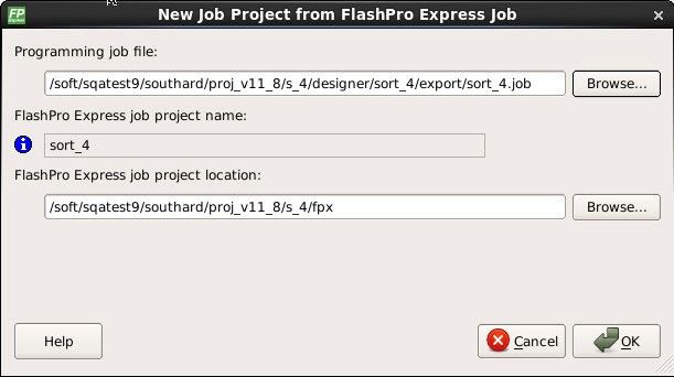
Getting Started

4.    Getting Started
      This section describes how to get started using FlashPro Express.

4.1   Starting FlashPro Express
      Start FlashPro Express by running the program at [installation folder] > bin > FPExpress.

4.2   FlashPro Express Interface
      The main FlashPro Express UI consists of a list of programmers and a chain table. This view displays the
      programmers connected to the machine, and the devices within the JTAG chain (Figure 4-1) or a single device with
      SPI Slave interface (Figure 4-2) specified in the job project file (PRO) file.
      Figure 4-1. FlashPro Express Programmers and Chain Table (JTAG Example)

      © 2021 Microchip Technology Inc.                       User Guide                              DS50003089B-page 8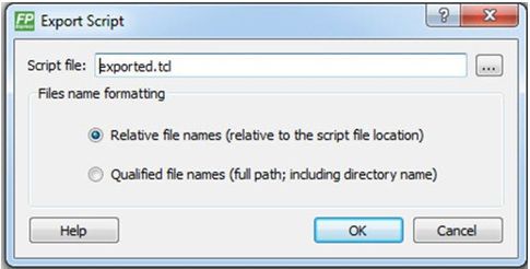
Getting Started

Figure 4-2. FlashPro Express Programmers and Chain Table (SPI Slave Example)

The following table describes the FlashPro actions you can perform. Devices specified as disabled in the job project
(*.pro) file are shown disabled and their HighZ value appears in the column header.
Table 4-1. FlashPro Actions

 To...                                                     Perform This Action...
 Display more information about a programmer.              Hover over the programmer Info icon.
 Change a programmer name.                                 Click the Name field.
 Enable or disable a programmer.                           Click the check box.
 Ping, Self-Test, Scan, Check Chain, or Remove it from     Right-click a programmer.
 the list.
 View additional information about a device and            Hover over the info icon of that device.
 programming file, if loaded.

The following table describes the device/programmer states.
Table 4-2. Device/Programmer States

 Device/Programmer State                                   Description
 IDLE                                                      Devices and programmers are idle and not executing
                                                           any programming action.
 DISABLED                                                  Devices that are not enabled for programming.
 PASSED                                                    Last programming operation passed.
 FAILED                                                    Last programming operation failed.

Note: SPI Slave mode is supported by FlashPro5 for SmartFusion2 and IGLOO2 devices, and by FlashPro6 for
SmartFusion2, IGLOO2, and PolarFire devices. JTAG is the default interface. RTG4 devices do not support SPI
Slave programming.

© 2021 Microchip Technology Inc.                         User Guide                                   DS50003089B-page 9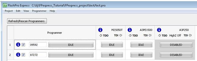
Getting Started

4.3   Creating a Job Project from a FlashPro Express Job
      When you are ready to hand off your design for production, create a job project.
        1.   In Libero, run Export FlashPro Express Job to create a container that will be used to transfer programming
             configuration information, including programming files, to the production programming tool FlashPro Express.
             Figure 4-3. Export FlashPro Express Job

        2.   In FlashPro Express, from the Project menu, choose New Job Project.
        3.   When prompted, specify the Programming Job file location that you just exported from Libero and the location
             to store the FlashPro Express job project. The job project name uses the programming job name and cannot
             be changed. Click OK to create and open a new job project for production programming.
      Figure 4-4. New Job Project from FlashPro Express Job Dialog Box

      © 2021 Microchip Technology Inc.                        User Guide                              DS50003089B-page 10
Getting Started
Figure 4-5. New Project from FlashPro Express Job Dialog Box in Developer Mode
In Developer mode, a new job project can also be created using Construct automatically option. This option can be
used to construct chain by scanning the physical chain connected to the selected programmer. This feature is
available only in JTAG mode. If multiple programmers are connected to the machine, select the desired programmer
by clicking on the pull down menu for connected programmers field.
4.4 Opening a Job Project
To start with FlashPro Express, load a job project (*.pro) file.
© 2021 Microchip Technology Inc. User Guide DS50003089B-page 11Getting Started
A job project opens if:
• At least one programmer is connected.
• At least one Microchip device is enabled for programming (Required for Operator Mode).
• Any enabled Microchip device for programming has a bitstream file loaded.
To open a job project:
1. From the Project menu, choose Open Job Project. The Open Project dialog box appears.
2. Find your project file or type in your project file name in the File name field.
3. Click Open.
Figure 4-6. FlashPro Express Launch Screen
4.5 Saving a Job Project
To save a job project, either:
• Click the Save button on the toolbar, or
• From the Project menu choose Save Job Project.
4.6 Programming Tutorials
The following programming tutorials describe real-world examples of using FlashPro.
© 2021 Microchip Technology Inc. User Guide DS50003089B-page 12Getting Started
4.6.1 Parallel Programming with FlashPro5/4/3/3X
Parallel programming allows you to program multiple Microchip devices in parallel with multiple programmers. In
parallel programming, all targeted devices are programmed with the same programming file (STAPL). The targeted
device or chain configuration that is connected to each programmer must be identical.
The FlashPro Express software together with the FlashPro5/4/3/3X programmers supports parallel programming via
a USB port. You can connect up to sixteen FlashPro5/4/3/3X's to a PC via a USB v1.1 or a USB v2.0 port.
FlashPro5/4/3/3X requires a self-powered hub.
Connecting FlashPro5/4/3/3X (a USB v2.0 enabled programmer) to USB v1.1 port increases device programming
time due to a slow data transfer rate on the USB v1.1 port in comparison to a USB v2.0 port.
The following figure shows how to connect a FlashPro5/4/3/3X programmer for parallel programming.
Figure 4-7. Connecting a FlashPro5/4/3/3X Programmer
An independent thread processes the STAPL file during parallel programming. In a Microchip test environment,
parallel programming is approximately five times faster than programming 16 devices sequentially.
Note: Microchip has tested Belkin PCI-USB cards and hubs, and found that parallel programming works best when
using the vendor's latest driver installed along with matching hubs.
4.6.2 Chain Programming Tutorial
This tutorial describes how to use FlashPro Express to program a multi-device, multi-programmer chain. This tutorial
uses the production programming flow that exports a programming job from Libero SoC, which includes chain
configuration, programmer settings, and bitstream files for programming, and creates a job project from a
programming job.
The following figure shows the chain used in this tutorial. M2S050T is device 1 and A3P250 is device 3.
• Device 1 is the first device to be programmed in the chain.
• Device 2 is the last device to be programmed in the chain.
• Device 3 is disabled and will not be programmed.
© 2021 Microchip Technology Inc. User Guide DS50003089B-page 13Getting Started
Figure 4-8. Chain Programming Devices
To program a chain:
1. From the Project menu, choose New Job Project from FlashPro Express Job.
2. Click Browse to load a Programming Job File, and specify your FlashPro Express job project location.
Click OK to continue, as shown in the following figure.
Figure 4-9. New Job Project from FlashPro Express Job
FlashPro Express displays your Job Project and programmers, as shown in the following figure. The Device/
Programmer states are:
– IDLE: Devices/programmers are idle and not executing any programming action.
– DISABLED: Devices that are not enabled for programming.
– PASSED: Last programming operation passed.
– FAILED: Last programming operation failed.
© 2021 Microchip Technology Inc. User Guide DS50003089B-page 14Getting Started
Figure 4-10. FlashPro Express with Loaded Job Project (JTAG Example)
Figure 4-11. FlashPro Express with Loaded Job Project (SPI Slave Example – SmartFusion2/IGLOO2
Only)
© 2021 Microchip Technology Inc. User Guide DS50003089B-page 15Getting Started
3. If your programmer is not listed, click the Refresh/Rescan button. To view device info, hover your mouse over
the Info icon. If a device is Disabled for programming, the HighZ status appears in the GUI.
4. Set the Programming Action in the drop-down menu to PROGRAM, as shown in the following figure.
Figure 4-12. Programming Action Set to PROGRAM
5. Click RUN. Detailed individual programmer and device status information appears in the Programmer List.
Your programmer status (PASSED or FAILED) appears in the Programmer Status Bar, as shown in the
following figure.
– Hover over the Programmer Status Bar to display information on the programmers.
– Hover over the FAILED status to list all programmers that failed programming.
– Hover over the PASSED status to list all the programmers that programmed successfully.
Figure 4-13. Chain Programming Complete
6. View the Log for Messages, Errors, Warnings and Info generated during programming.
© 2021 Microchip Technology Inc. User Guide DS50003089B-page 16Programming Connectivity and Interface
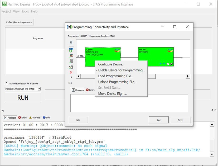
5. Programming Connectivity and Interface
The Programming Connectivity and Interface option can be selected from Tools > Programming Connectivity and
Interface.
Figure 5-1. Programming Connectivity and Interface Option in Tools Menu
By default, the tool selects the first enabled programmer and opens the Programming Connectivity and Interface
dialog box with an existing JTAG chain or SPI Slave device. If there is no programmer enabled, an error message is
shown. The user can disable all programmers, except the one which is used by the FlashPro Express tool.
The selected programmer and current programming interface are shown in the dialog box for the user reference. The
main window’s programmer table is cleared as soon as the chain dialog box is opened and will be populated with
saved changes or restored to previous state if changes are canceled when the dialog box is closed.
Figure 5-2. Programming Connectivity and Interface Dialog Box with Configure Chain Options
For JTAG Interface, the same configure chain options are available as in Libero SoC tool.
For SPI Slave interface, the following options are available:
• Set Programming Interface: Selects JTAG or SPI Slave mode.
• Add Microsemi Device: Adds a Microsemi device to the chain.
• Delete device: Deletes selected devices in the grid.
© 2021 Microchip Technology Inc. User Guide DS50003089B-page 17Programming Connectivity and Interface
• Zoom In: Zoom into the grid.
• Zoom Out: Zoom out of the grid.
The devices used in FlashPro Express tool have the following context menu options:
• Configure Device: Configure device is same as the one in Libero SoC tool. Configure device option allows to
configure device by loading programming file (but not a SPI Flash file) or to set device family and die.
• Enable/Disable Device for Programming: Enables or disables device for programming.
• Load Programming File: Loads the programming file.
• Unload Programming File: This option is enabled if programming file loaded.
• Load SPI Flash File: Loads a SPI Flash file. This option is always enabled. It is available for PolarFire and
PolarFire SoC devices.
• Unload SPI Flash File: This option is enabled if SPI Flash file is loaded. It is available for PolarFire and
PolarFire SoC devices.
• Set Serial Data: This option is disabled; serialization is not supported.
• Move Device: to left/right
There is no option to configure/select programming action or SPI Flash action. This option is only available in the
main table because it depends on the developer mode option to run one programming action for all devices or run an
action selected for each device.
From Libero SoC v12.6 onwards, you can change a device type by loading the programming file for a different device
type. This is consistent with Libero flow.
In the chain dialog box and in the main table, the user can load the programming file for a different device type with a
GUI confirmation. The chain tool also allows the user to re-configure the device by selecting a different family and a
die. In this case, no confirmation is required.
In the batch mode, a programming file is loaded with a warning.
© 2021 Microchip Technology Inc. User Guide DS50003089B-page 18Programmer Settings and Operations
6. Programmer Settings and Operations
This section describes the FlashPro Express settings and operation.
6.1 Introduction
The FlashPro Express software allows you to connect multiple programmers to your computer. With each
programmer you select, you can perform a ping, conduct a self-test, scan and check the chain, and remove, enable,
or disable the JTAG chain, as shown in the following figure.
Figure 6-1. FlashPro Express Right-Click Menu
6.2 Programmer Settings
To view the Programmer Settings dialog box, in the Libero SoC Design Flow window, expand Configure Hardware,
double-click Configure Programmer, or right-click Configure Programmer and choose Programmer Settings.
For the JTAG interface, you can set specific voltage and force TCK frequency values for your programmer in this
dialog box. For the SPI Slave interface, you can set specific voltage and force SCK frequency values for your
programmer. SPI Slave mode is supported by FlashPro5 for SmartFusion2 and IGLOO2 devices, and by FlashPro6
for SmartFusion2, IGLOO2, and PolarFire devices. SPI Slave mode is not supported for RTG4 devices. JTAG is the
default interface.
© 2021 Microchip Technology Inc. User Guide DS50003089B-page 19Programmer Settings and Operations
Figure 6-2. Programmer Settings
The Programmer Settings dialog box includes options for FlashPro6/5/4/3/3X. Limitation of the TCK frequency for the
selected programmer are:
• FlashPro6: 1, 2, 3, 4, 5, 6, 7, 8, 9, 10, 11, 12, 13, 14, 15, 16, 17, 18, 19, 20 MHz
• FlashPro5: 1, 2, 3, 4, 5, 6, 10, 15, 30 MHz
• FlashPro4: 1, 2, 3, 4, 5, 6 MHz
• FlashPro3/3X: 1, 2, 3, 4, 6 MHz TCK frequency limits by target device (refer to the target device data sheet)
During execution, the frequency set by the FREQUENCY statement in the PDB/STAPL file overrides the TCK
frequency setting you select in the Programmer Settings dialog box, unless you also select the Force TCK
Frequency check box.
Limitation of the SCK frequency for the selected programmer are: 1.00, 2.00, 2.50, 3.33, 4.00, 5.00, 6.67, 8.00,
10.00, 13.33, and 20.00 MHz
6.2.1 FlashPro5/4/3/3X Programmer Settings
For FlashPro5/4/3/3X, if you choose the Force TCK Frequency, select the appropriate MHz frequency. For
FlashPro4/3X settings, you can switch the TCK mode between a Free running clock and a Discrete clocking. Use
discrete clocking when there is a JTAG non-compliant device in a chain with Microchip devices. After you make your
selections(s), click OK.
6.2.1.1 Default Settings
• The Force TCK Frequency option is unchecked to instruct the FlashPro5/4/3/3X to use the TCK frequency
specified by the Frequency statement in the PDB/STAPL file(s).
© 2021 Microchip Technology Inc. User Guide DS50003089B-page 20Programmer Settings and Operations
• The FlashPro5/4/3/3X default TCK mode setting is Free running clock.
6.2.2 TCK Setting for Force TCK Frequency
If Force TCK Frequency is checked in the Programmer Setting, the selected TCK value is set for the programmer
and the Frequency statement in the PDB/STAPL file is ignored.
6.2.3 Default TCK Frequency
If the IPD/STAPL file or Chain does not exist, the default TCK frequency is set to 4 MHz.
If more than one Microchip flash device is targeted in the chain, the FlashPro Express software passes through all of
the files and searches for the "freq" keyword and the "MAX_FREQ" Note field. The FlashPro Express software uses
the lesser value of all the TCK frequency settings and the "MAX_FREQ" Note field values.
6.3 Ping Programmers
Right-click a programmer and choose Ping.
Note: To ping new programmers quickly, click the Refresh/Rescan for Programmers button.
6.4 Performing a Self-Test
Before performing a self-test, connect the programmer to the self-test board that came with your programmer. Then
right-click the programmer you want to self-test and choose Self Test.
Note: Self-test is not supported with FlashPro5/4 programmers. These programmers are tested rigorously at the
factory during production.
6.5 Scanning and Checking a Chain
The scan chain operation scans and analyzes the JTAG chain connected to programmers you selected and checks
that a scanned chain matches the chain configured in FlashPro Express.
To scan a chain, right-click the programmer you want to scan and choose Scan and check chain.
6.6 Enabling and Disabling Programmers
After loading a job project, you can enable, disable, or remove a programmer, as well as ping, self-test, run scan, and
check chain on any of the connected programmers. These actions are available in the right-click menu for each
programmer in the programmer column.
Check the check box next to a programmer in the Programmer column to enable the programmer or uncheck the
check box to disable the programmer.
6.7 Renaming a Programmer
Enter a new programmer name in the Programmer window to rename the programmer. By default, the programmer
name is the same as the programmer ID.
6.8 Removing a Programmer
To remove a programmer, right-click the programmer and choose Remove.
6.9 Selecting and Running an Action
FlashPro Express supports the following programming actions:
© 2021 Microchip Technology Inc. User Guide DS50003089B-page 21Programmer Settings and Operations
• DEVICE_INFO
• ENC_DATA_AUTHENTICATION. This action is visible when every device in the chain contains encrypted
bitstream files. Selecting this action checks each bitstream file for authentication.
• ERASE
• PROGRAM
• READ_IDCODE
• VERIFY
To select a programming action, select an action from the Programming Action drop-down menu in FlashPro
Express, as shown in the following figure.
Figure 6-3. FlashPro Express Programming Actions
To run the selected programming action, click the RUN button below the Programming Action drop-down menu.
© 2021 Microchip Technology Inc. User Guide DS50003089B-page 22Chain Programming
7. Chain Programming
This section describes how to perform chain programming.
7.1 Chain Order
Chain Programming allows you to program several devices at one time. The order of devices in the chain imported
from Job Project must match the physical chain to be programmed.
The TDO for the first device connects to the programmer, and the last device's TDI connects to the programmer. The
devices in the chain go in order from a device's TDI into the next device's TDO, as shown in the following figure.
Figure 7-1. Chain Order
7.2 Multiple Device Chain Programming
The FlashPro Express software allows direct chain programming without generating a chain STAPL file. Each device
is programmed in sequential order, starting from device 1 to device N (see the following example).
TDI > Device N > Device N-1 >… > Device 2 > Device 1 > TDO
7.2.1 Device Programming Compatibility
PolarFire, SmartFusion2, IGLOO2, and RTG4 devices can be programmed in the same chain.
7.2.2 Programmer Support
FlashPro5/4/3/3X supports PolarFire, SmartFusion2, IGLOO2, and RTG4 devices. The Vpump on FlashPro5/4/3/3X
is designed to support the programming of only one device. Make sure that Vpump, Vcc, and Vjtag are provided on
board for chain programming. Connect the Vpump to the header as the Flashpro Express software will attempt to
check for all external supplies, including Vpump, to ensure successful programming. There is no limitation to the
chain length; however, ensure that the JTAG signal integrity and the timing are preserved.
© 2021 Microchip Technology Inc. User Guide DS50003089B-page 23FlashPro Express Modes
8. FlashPro Express Modes
Starting with Libero SoC v12.5, FlashPro Express supports two modes:
• Operator mode
• Developer mode
Operator mode is a current flow that provides production programming. It is the default mode and allows you to run
selected actions for individual and all devices.
Developer mode allows you to:
• Update jobs before running programming.
• Enable or disable chain devices.
• Load design and SPI Flash Programming files and select different programming actions for each chain device
and SPI-Flash.
• Run selected actions for individual and all devices.
You select Operator or Developer mode using the Preference dialog box (Project > Preferences). The preference is
saved per user per machine on Windows and per user on Linux. The mode preference remains the same until you
change it.
Figure 8-1. FlashPro Express Mode Preference Dialog (Windows)
© 2021 Microchip Technology Inc. User Guide DS50003089B-page 24FlashPro Express Modes
Figure 8-2. FlashPro Express Mode Preference Dialog (Linux)
The FlashPro Express mode can be switched before opening a job. If a job is opened, you are prompted to confirm
closing of the job to save the mode preference after clicking the OK button.
After a job is opened in Developer mode, each device displays:
• An info ( ) icon with device specific data.
• Design icon ( ). The per-device selected action appears next to the icon if the Run selected action for all
devices option is unselected.
• SPI Flash icon ( ) if SPI Flash programming is available for the device. The per-device selected SPI Flash
action appears next to the icon if the Run selected action for all devices option is unselected.
• Configure button ( ) providing a menu of configuration options based on the device. The configure button is
enabled when no programming action is running.
The following list describes Developer mode features:
• Device configuration options
Figure 8-3. Device Options to Program Design
© 2021 Microchip Technology Inc. User Guide DS50003089B-page 25FlashPro Express Modes
Figure 8-4. Device Options to Program Design and SPI Flash
• Enable/Disable device for programming. The option allows the device to be enabled or disabled (put in
“bypass”). You must load the programming file when enabling a device that is in “bypass,” with no programming
file associated with the device or SPI-Flash. The device header info tooltip is updated with selected
programming action if enabled or “bypass” if disabled.
Note: The job cannot be saved if all devices are disabled or if any enabled devices do not have a loaded
programming file. If all the devices are disabled, an actions combo box and a Run button are disabled.
• Load Programming File. The option is available for the enabled devices to load a different programming file for
the target device. FlashPro Express requires all programming files to be in the local job folder. When loading a
programming file from outside the job folder the file will be copied to the job folder first and then loaded for the
selected device. The user must confirm copying the programming file to the job folder and overwriting the
existing file.
• Select a programming action and configure actions and procedures per device. The option allows the selection
of the programming action and configuration of the actions’ procedures. The option is available for an enabled
device that has programming file loaded, and when the Run selected action for all devices option is
unselected.
• Load SPI Flash file. This option allows you to load a different SPI Flash programming file.
• Select SPI Flash Action. The option allows the selection of the programming action for the SPI Flash. The option
is available for the enabled device that has SPI Flash Programming File loaded, and when the Run selected
action for all devices option is unselected.
• Program device selected actions. In Developer mode, when the Run selected action for all devices check box
is selected, FlashPro Express runs selected action from the drop-down list below the check box for all enabled
devices – similar to Operator mode.
© 2021 Microchip Technology Inc. User Guide DS50003089B-page 26FlashPro Express Modes
Figure 8-5. Run One Action for All Chain Devices
When the Run selected action for all devices check box is unselected, the actions drop-down list is disabled.
FlashPro Express runs the programming actions for the enabled device and SPI Flash, as selected uniquely for
each device.
Figure 8-6. Run Device Selected Actions
© 2021 Microchip Technology Inc. User Guide DS50003089B-page 27TCL Commands
9. TCL Commands
This section describes the FlashPro Express Tcl commands.
9.1 About Tcl Commands
A Tool Command Language (Tcl) file contains scripts for simple or complex tasks. You can run scripts from the
Windows command line, or store and run a series of Tcl commands in a *.tcl batch file.
You can run Tcl commands from scripts or from a Windows or Linux command line. Tcl commands are case sensitive.
However, their arguments are not.
For information about all Tcl commands supported by FlashPro Express, see the Tcl Command Reference Guide
(SmartFusion2, IGLOO2, RTG4) and Tcl Command Reference Guide (PolarFire).
9.2 Executing a Tcl Script File in FlashPro Express
To execute a Tcl script in FlashPro Express:
1. From the File menu, choose Execute Script to display the Run Script dialog box.
Figure 9-1. Run Script Dialog Box
2. Click the Browse button to display the Open dialog box, in which you can go to the folder containing the script
file to open. When you click Open, FlashPro Express enters the full path and script filename into the Run
Script dialog box.
3. In the Arguments box, enter the arguments to pass to your Tcl script. Separate each argument by a space
character.
4. Click Run.
9.3 Running Tcl Scripts from the Command Line
You can run Tcl scripts from a Windows or Linux command line.
1. At the prompt, type the path to the Microchip software followed by the word SCRIPT, a colon, and the name of
the script file, as follows:
/bin/FPExpress.exe SCRIPT:
The following example executes in batch mode the script foo.tcl:
/bin/FPExpress.exe script:foo.tcl
The following example executes in batch mode the script foo.tcl and exports the log in the file foo.txt:
© 2021 Microchip Technology Inc. User Guide DS50003089B-page 28TCL Commands
/bin/FPExpress.exe script:foo.tcl logfile:foo.txt
The following example executes in batch mode the script foo.tcl, creates a console where the log is displayed
briefly, and exports the log in the file foo.txt:
/bin/FPExpress.exe script:foo.tcl
console_mode:brief logfile:foo.txt
If you leave console_mode unspecified or set it to hide, FlashPro Express executes without a console window.
To leave the console window open, run the script with the console_mode parameter set to show, as in the
following example:
/bin/FPExpress.exe script:foo.tcl
console_mode:show logfile:foo.txt
2. To pass arguments to the Tcl script from the command line, use the SCRIPT_ARGS variable, as follows:
/bin/FPExpress.exe SCRIPT:
SCRIPT_ARGS:"param1 param2 param3"
Arguments passed to a Tcl script can be accessed through the Tcl variables argc and argv. The following
examples show how a Tcl script accesses these arguments:
puts "Script name: $argv0"
puts "Number of arguments: $argc" set i 0
foreach arg $argv { puts "Arg $i : $arg" incr i
}
Note: If the script name is protected with double quotes, script names can contain spaces. For example:
FPExpress script:"FPExpress tcl/foo 1.tcl"
9.4 Exporting Tcl Scripts from FlashPro Express
To export Tcl scripts from FlashPro Express:
1. From the File menu, choose Export Script File.
2. Enter the filename and click Save. The Export Script Options dialog appears, as shown in the following figure.
Figure 9-2. Script Export Options Dialog Box
3. Check the Include commands from current project only to export commands of the current project only.
You can specify the filename formatting by selecting Relative filenames (relative to the current directory) or
Qualified filenames (absolute path, including the directory name).
4. Click OK.
© 2021 Microchip Technology Inc. User Guide DS50003089B-page 29Troubleshooting
10. Troubleshooting
This section lists the exit codes for PolarFire, RTG4, and SmartFusion2 and IGLOO2.
10.1 PolarFire Exit Codes
The following table lists the PolarFire exit codes.
Table 10-1. PolarFire Exit Codes
Error Exit Message Exit Possible Cause Possible Solution
Code Code
Passed (no error) 0 — —
0x8002 Failed to disable 5 Unstable voltage level. Monitor related power supplies that cause
programming mode the issue during programming; check for
Signal integrity issues on
transients outside of Microchip
Failed to set JTAG pins.
specifications. See your device data sheet
programming mode
for more information on transient
specifications.
Monitor JTAG supply pins during
programming; measure JTAG signals for
noise or reflection.
0x8032 Device is busy 5 Unstable VDDIx voltage Monitor related power supplies that cause
level. the issue during programming; check for
transients outside of Microchip
specifications. See your device data sheet
for more information on transient
specifications.
0x8003 Failed to enter 5 Unstable voltage level. Monitor related power supplies that cause
programming mode the issue during programming; check for
Signal integrity issues on
transients outside of Microchip
JTAG pins.
specifications. See your device data sheet
DEVRST_N is tied to for more information on transient
LOW. specifications.
Monitor JTAG supply pins during
programming; measure JTAG signals for
noise or reflection.
Tie DEVRST_N to HIGH prior to
programming the device.
0x8004 Failed to verify 6 Incorrect programming Choose the correct programming file and
IDCODE file. select the correct device in the chain.
Incorrect device in chain. Measure JTAG pins and noise for reflection.
If TRST is left floating then add pull-up to pin.
Signal integrity issues on
JTAG pins. Reduce the length of Ground connection.
© 2021 Microchip Technology Inc. User Guide DS50003089B-page 30Troubleshooting
...........continued
Error Exit Message Exit Possible Cause Possible Solution
Code Code
0x8005 Failed to verify 11 Device is programmed Verify the device is programmed with the
FPGA Array with a different design or correct data/design.
0x8006
the component is blank.
Failed to verify Monitor related power supplies that cause
0x8007
Fabric Configuration Unstable voltage level. the issue during programming; check for
0x8008 transients outside of Microchip
Failed to verify Signal integrity issues on
specifications. See your device data sheet
Security JTAG pins.
for more information on transient
Failed to verify specifications.
sNVM
Monitor JTAG supply pins during
programming; measure JTAG signals for
noise or reflection.
0x8013 External digest –18 External Digest check via Need to use a bitstream file which has a
check via JTAG/SPI JTAG/SPI Slave is valid FlashLock/UPK1 to enable external
Slave is disabled. disabled. digest check via JTAG/SPI Slave.
0x8015 FPGA Fabric digest –20 FPGA Fabric is either If the Fabric is erased, deselect procedure
verification: FAIL erased or the data has DO_ENABLE_FABRIC from action
been corrupted or VERIFY_DIGEST.
Deselect procedure
tampered with.
'DO_ENABLE_FAB
RIC' to remove this
digest check.
0x8016 sNVM digest –20 sNVM is either erased or If the sNVM is erased, deselect procedure
verification: FAIL the data has been DO_ENABLE_SNVM from action
corrupted or tampered VERIFY_DIGEST.
Deselect procedure
with.
'DO_ENABLE_SNV
M' to remove this
digest check.
0x8018 User security –20 Security segment is either If the security is erased, deselect procedure
policies segment erased or the data has DO_ENABLE_SECURITY from action
digest verification: been corrupted or VERIFY_DIGEST.
FAIL tampered with.
Deselect procedure
'DO_ENABLE_SEC
URITY' to remove
this digest check.
0x8019 UPK1 segment –20 UPK1 segment is either If the UPK1 is erased, deselect procedure
digest verification: erased or the data has DO_ENABLE_SECURITY from action
FAIL been corrupted or VERIFY_DIGEST.
tampered with.
Deselect procedure
'DO_ENABLE_SEC
URITY' to remove
this digest check.
© 2021 Microchip Technology Inc. User Guide DS50003089B-page 31Troubleshooting
...........continued
Error Exit Message Exit Possible Cause Possible Solution
Code Code
0x801A UPK2 segment –20 UPK2 segment is either If the UPK2 is erased, deselect procedure
digest verification: erased or the data has DO_ENABLE_UKS2 from action
FAIL been corrupted or VERIFY_DIGEST.
tampered with.
Deselect procedure
'DO_ENABLE_UKS
2' to remove this
digest check.
0x801B Factory row and –20 Factory row and factory
factory key segment key segment have been
digest verification: erased through
FAIL zeroization or the data
has been corrupted or
tampered with.
0x801C Fabric configuration –20 Fabric configuration If the Fabric configuration is erased, deselect
segment digest segment is either erased procedure DO_ENABLE_FABRIC from
verification: FAIL or has been corrupted or action VERIFY_DIGEST.
tampered with.
Deselect procedure
'DO_ENABLE_FAB
RIC' to remove this
digest check.
0x8052 UEK1 segment –20 UEK1 segment is either If the UEK1 is erased, deselect procedure
digest verification: erased or the data has DO_ENABLE_UEK1 from action
FAIL been corrupted or VERIFY_DIGEST.
tampered with.
Deselect procedure
'DO_ENABLE_UEK
1' to remove this
digest check.
0x8053 UEK2 segment –20 UEK2 segment is either If the UEK2 is erased, deselect procedure
digest verification: erased or the data has DO_ENABLE_UEK2 from action
FAIL been corrupted or VERIFY_DIGEST.
tampered with.
Deselect procedure
'DO_ENABLE_UEK
2' to remove this
digest check.
0x8054 DPK segment digest –20 DPK segment is either If the DPK is erased, deselect procedure
verification: FAIL erased or the data has DO_ENABLE_DPK from action
been corrupted or VERIFY_DIGEST.
Deselect procedure
tampered with.
'DO_ENABLE_DPK'
to remove this
digest check.
0x8057 SMK segment –20 SMK segment is either If the SMK is erased, deselect procedure
digest verification: erased or the data has DO_ENABLE_SMK from action
FAIL been corrupted or VERIFY_DIGEST.
tampered with.
© 2021 Microchip Technology Inc. User Guide DS50003089B-page 32Troubleshooting
...........continued
Error Exit Message Exit Possible Cause Possible Solution
Code Code
0x8058 User Public Key –20 User Public Key segment If the User Public Key is erased, deselect
segment digest is either erased or the procedure
verification: FAIL data has been corrupted DO_ENABLE_USER_PUBLIC_KEY from
or tampered with. action VERIFY_DIGEST.
0x801D Device security –21 The device is protected Run DEVICE_INFO to view security features
prevented operation with user pass key 1 and that are protected.
the bitstream file does not
Provide a bitstream file with a user pass key
contain user pass key 1.
1 that matches the user pass key 1
User pass key 1 in the programmed into the device.
bitstream file does not
match the device.
0x801F Programming Error. –22 Bitstream file has been Regenerate bitstream file.
corrupted or was
Monitor related power supplies that cause
incorrectly generated.
the issue during programming; check for
transients outside of Microchip
specifications. See your device data sheet
for more information on transient
specifications.
Bitstream or data is Unstable voltage level. Monitor JTAG supply pins during
corrupted or noisy programming; measure JTAG signals for
Signal integrity issues on
noise or reflection.
JTAG pins.
0x8021 Programming Error. –23 File contains an encrypted Provide a programming file with an
key that does not match encryption key that matches that on the
Invalid/Corrupted
the device device.
encryption key
File contains user First program security with master
encryption key, but device programming file, then program with user
has not been programmed encryption 1/2 field update programming
with the user encryption files.
key.
0x8023 Programming Error. –24 Design version is not Generate a programming file with a design
higher than the back-level version higher than the back level version.
Back level not
programmed device.
satisfied
0x8001 Failure to read DSN –24 Device is in System TRSTB should be driven High or disable
Controller Suspend Mode. System Controller Suspend Mode.
Check board connections.
0x8027 Programming Error. –26 Device does not support Generate a programming file with the correct
the capabilities specified capabilities for the target device.
Insufficient device
in programming file.
capabilities
0x8029 Programming Error. –27 Incorrect programming Choose the correct programming file and
Incorrect DEVICEID file. select the correct device in chain.
Incorrect device in chain. Measure JTAG pins and noise or reflection. If
TRST is left floating, then add pull-up to pin.
Signal integrity issues on
JTAG pins. Reduce the length of ground connection.
© 2021 Microchip Technology Inc. User Guide DS50003089B-page 33Troubleshooting
...........continued
Error Exit Message Exit Possible Cause Possible Solution
Code Code
0x802B Programming Error. –28 Programming file version Generate programming file with latest
is out of date. version of Libero SoC.
Programming file is
out of date, please
regenerate.
0x8030 Programming Error –31 FAB_RESET_N is tied to FAB_RESET_N should be tied to HIGH.
ground.
Invalid or
inaccessible Device
Certificate
0x8032 Instruction timed out –32 Unstable voltage level. Monitor related power supplies that cause
the issue during programming; check for
0x8034 Signal integrity issues on
transients outside of Microchip
JTAG pins.
0x8036 specifications. See your device data sheet
for more information on transient
0x8038
specifications.
Monitor JTAG supply pins during
programming; measure JTAG signals for
noise or reflection.
0x8010 Failed to unlock –35 Pass key in file does not Provide a programming file with a pass key
user pass key 1 match device. that matches pass key programmed into the
device.
0x8011 Failed to unlock –35 Pass key in file does not Provide a programming file with a pass key
user pass key 2 match device. that matches pass key programmed into the
device.
0x804F Bitstream –38 Unstable voltage level. Monitor related power supplies that cause
programming action the issue during programming; check for
Bitstream programming
is disabled transients outside of Microchip
action has been disabled
specifications. See your device data sheet
in Security Policy
for more information on transient
Manager.
specifications.
Need to use a bitstream file which has a
valid FlashLock/UPK1 to enable the
bitstream programming action.
0x805B Error, security must –42 Security only bitstream Use this bitstream on a blank device or
be either programming on a generate a new bitstream that contains the
programmed on a programmed device. FPGA Fabric design along with the security.
blank device or with
the FPGA Fabric
design
10.2 RTG4 Exit Codes
The following table lists the RTG4 exit codes.
© 2021 Microchip Technology Inc. User Guide DS50003089B-page 34Troubleshooting
Table 10-2. RTG4 Exit Codes
Error Code Exit Message Possible Cause Possible Solution
Passed (no error) — —
0x8001 Failure to read DSN Device is in System TRSTB should be driven High on device
Controller Suspend power up.
Mode.
Disable System Controller Suspend Mode in
Check board the Programming Bitstream Settings tool
connections. within Libero and reprogram the device.
0x8002 Device is busy Unstable VDDIx voltage Monitor related power supplies that cause the
level. issue during programming; check for
transients outside of Microchip specifications.
See your device data sheet for more
information on transient specifications.
0x8003 Failed to enter Unstable voltage level. Monitor related power supplies that cause the
programming mode issue during programming; check for
Signal integrity issues on
transients outside of Microchip specifications.
JTAG pins.
See your device data sheet for more
DEVRST_N is tied to information on transient specifications.
LOW.
Monitor JTAG supply pins during
programming; measure JTAG signals for
noise or reflection.
Tie DEVRST_N to HIGH prior to
programming the device.
0x8004 Failed to verify Incorrect programming Choose the correct programming file and
IDCODE file. select the correct device in the chain.
Incorrect device in chain. Measure JTAG pins and noise for reflection.
If TRST is left floating then add pull-up to pin.
Signal integrity issues on
JTAG pins. Reduce the length of Ground connection.
0x8005 Failed to verify Programming file is for Generate a programming file for RT4G150
IDCODE RT4G150_ES and device device.
RT4G150_ES is RT4G150.
Choose the correct programming file and
STAPL file is not Incorrect programming select the correct device in the chain.
compatible with file Incorrect device in
Measure JTAG pins and noise for reflection.
RT4G150 production chain.
If TRST is left floating then add pull-up to pin.
devices. You must use
Signal integrity issues on
a STAPL file for Reduce the length of Ground connection.
JTAG pins.
RT4G150 device.
0x8006 Failed to verify Programming file is for Generate a programming file for
IDCODE RT4G150 RT4G150 and device is RT4G150_ES device.
RT4G150_ES.
STAPL file is not Choose the correct programming file and
compatible with Incorrect programming select the correct device in the chain.
RT4G150_ES file Incorrect device in
Measure JTAG pins and noise for reflection.
chain.
devices. You must use If TRST is left floating then add pull-up to pin.
a STAPL file for Signal integrity issues on
Reduce the length of Ground connection.
RT4G150_ES device. JTAG pins.
© 2021 Microchip Technology Inc. User Guide DS50003089B-page 35You can also read