PNeuton mini Transport Ventilator - Airon Corporation
←
→
Page content transcription
If your browser does not render page correctly, please read the page content below
pNeuton®
Transport Ventilator

         mini

  Operators Manual

              97041
       CD-I-005 Rev J
   Released 12 June 2019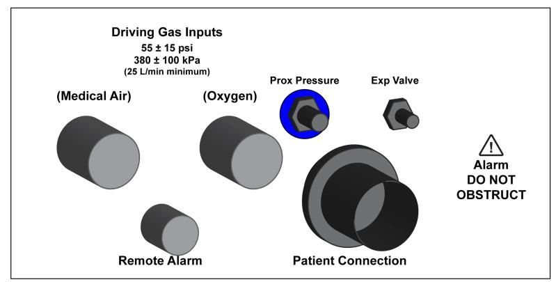
The pNeuton® Ventilator is under US patent protection.
              (Patent # 6,591,835)

   pNeuton is a Registered Trademark of the Airon
                    Corporation

       Copyright © 2012 by Airon Corporation

                      Manufactured by:

            Airon Corporation
            751 North Drive
            Unit 6
            Melbourne, Florida 32934
            USA

            Tel: 888-448-1238 (toll free USA & Canada)
                 +1-321-821-9433
            Fax: +1-321-821-9443

            www.AironUSA.com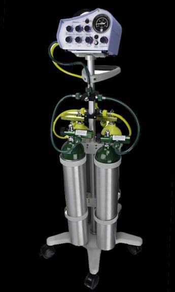
Table of Contents

Section 1. General Description ............................              1-1
   Indications for Use ..........................................        1-1
   Contraindications ............................................        1-2

Section 2. Warnings, Cautions, Notes .................                   2-1
   Warnings .........................................................    2-1
   Cautions ..........................................................   2-3
   Notes .........................................................…..    2-4
   Medical Symbol Key ……………………………                                        2-7

Section 3. Controls and Patient Safety Systems ..                        3-1
   Front Panel ......................................................    3-1
   Side Panel .......................................................    3-4
   Unique Device Identifier………………………..                                   3-6
   Internal Patient Safety Systems .......................               3-7

Section 4. Operating Instructions .........................              4-1
   Ventilator Set-up ..............................................      4-1
   Operational Verification ....................................         4-2
   Patient Ventilation ............................................      4-3
   Inspiratory and Expiratory Time Controls……..                          4-4
   Peak Pressure and Continuous Flow Controls.                           4-5
   PEEP/CPAP Control ……………………………                                         4-6
   Oxygen Control ...............................................        4-6
   High Pressure Alarm ……………………………                                       4-6
   Disconnect Alarm ……………………………….                                        4-7
   Hypobaric Operation ........................................          4-8

Section 5. Patient Circuit ......................................        5-1
   Infant / Pediatric Circuit ....................................       5-1
   Ventilator Connection .......................................         5-2
   Single-Use only Devices/Accessories ………..                             5-3

Section 6. Accessories ……………………………. 6-1

Section 7. Theory of Operation ............................. 7-1

pNeuton mini Ventilator                                                        I
Pneumatic System Diagram ............................            7-1
    Pneumatic System Description ........................            7-2
    Management of Patient Tidal Volume ……..….                        7-3
    CPAP System .........…………………………….                                7-4
    Oxygen Delivery System ..................................        7-5
    MRI Compatibility ........................................….     7-7
    High Pressure Alarm ……………………………                                  7-8
    Disconnect Alarm ………………………………..                                  7-9
    Low Gas Supply Alarm ………………………….                                 7-10

Section 8. Troubleshooting ..................................... 8-1

Section 9. Cleaning and Maintenance ................. 9-1
   Cleaning the Ventilator .................................... 9-1
   Cleaning / Disinfecting the Patient Circuit ....... 9-1
   Routine Maintenance ...................................... 9-1
   Factory Preventative Maintenance..................... 9-1

Section 10. Specifications ......................................    10-1
   General Description .........................................     10-1
   Ventilator System Performance .......................             10-1
   Alarm System ……………………………………                                       10-2
   Environmental and Physical Characteristics ....                   10-3
   Power Sources .................................................   10-3

Section 11. Limited Warranty ................................. 11-1

Section 12. Index ................................................... 12-1

pNeuton mini Ventilator                                                 II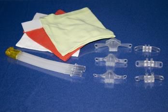
pNeuton mini Transport Ventilator
             Section 1: General Description

The pNeuton (pronounced "new-ton") mini is a small,
lightweight transport ventilator designed for use on patients
from neonatal to child in size, 400 grams to 25 kg. It is a
time cycled, flow limited ventilator providing Intermittent
Mandatory Ventilation (IMV). In this mode of ventilation,
an adjustable inspiratory time, expiratory time, and flow are
delivered to the patient. The patient is allowed to breath
spontaneously between the mandatory breaths with
minimal work of breathing. A built-in PEEP / CPAP system
can be set to provide expiratory positive pressure. The
delivered oxygen is adjustable from 21% to 100%, with
oxygen and compressed air as the driving source gas.

The pNeuton mini is a pneumatic ventilator. Electrical
power is not required for patient ventilation. mini has been
specifically designed for patient support during transport
and non-critical care unit mechanical ventilation. It may be
used during intra and inter-hospital transport, in aircraft, on
ambulances, in delivery suites, emergency rooms, MRI
and other radiology suites.

Indications for Use

The pNeuton mini Ventilator is intended for continuous
mechanical ventilation of patients in the following patient
populations and use locations:

Patient population – neonatal / infant / child patients 400
grams to 25 Kg who require the following general types of
ventilatory support:
• positive pressure ventilation delivered invasively (via
    an ET tube) or non-invasively (via a mask or nasal
    prongs)

pNeuton mini Ventilator                                  1-1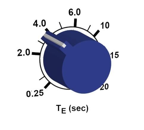
•   CMV and IMV modes of ventilation
•   with or without PEEP / CPAP
•   with oxygen or a mixture of air and oxygen

The ventilator is suitable for use in:
• Inter and intra-hospital patient transport
• Hospital ICU transport applications including delivery
   rooms, emergency, radiology, surgery, post-anesthesia
   / recovery and MRI departments
• Air & ground transport – pressurized and non-
   pressurized aircraft (to 15,000 ft)

Contraindications

The following conditions contraindicate the use of the
pNeuton mini Ventilator:
• Patients undergoing procedures with flammable
   anesthetic gasses
• Patients undergoing hyperbaric treatment
• Patients requiring tidal volumes greater than 500 ml.

pNeuton mini Ventilator                             1-2
Section 2: Warnings, Cautions, Notes

The pNeuton mini Ventilator is intended for use by
properly trained personnel under the direct supervision of
licensed medical Physician or Practitioner only. Personnel
must become thoroughly familiar with this Operators
Manual prior to using the pNeuton mini Ventilator on a
patient.

As used in this manual, the following terms mean:
   Warning: Indicates the possibility for injury to the
               patient or the operator
   Caution: Indicates the possibility of damage to the
               device
   Note:       Places emphasis on an operating
               characteristic

Warnings

This manual serves as a reference. The instructions in this
manual are not intended to supersede the physician’s
instructions regarding the use of the pNeuton mini
Ventilator.

The operator should read and understand this entire
manual before using the pNeuton mini Ventilator.

     DO NOT use the pNeuton mini Ventilator in
conjunction with anesthetics or in contaminated
(hazardous, explosive) atmospheres. Only compressed
oxygen and air may be used.

     DO NOT use conductive (anti-static) patient breathing
circuits. The only approved patient circuits for use with
pNeuton mini Ventilator are the Airon circuits listed in
Section 5 of this manual. Any other patient circuit should
NOT be used and may lead to patient harm.
pNeuton mini Ventilator                               2-1
Two different diameter patient circuits are used with the
pNeuton mini, based upon patient size. The 10 mm ID
circuit is designed for neonatal and infant patients. The 15
mm ID circuit is designed for children and pediatric
patients. DO NOT use the 10 mm neonatal circuit on large
children or at inspiratory flows of 10 L/min or higher.

     The proper attachment of the circuit’s small tubing to
the Expiratory Valve and Proximal Pressure connections of
the ventilator are very important. Connecting the tubes to
the wrong connectors will cause the ventilator to
malfunction and not provide ventilation. DO NOT cross
connect these tubes.

     The Airon patient circuit is a single use, disposable
device. Cleaning, reprocessing and / or reuse of this
device is not recommended. Reprocessing may cause a
change in ventilation characteristics. The circuit and all
components are sold clean and non-sterile.

      The Operational Verification tests as described in this
manual (Section 4) must be performed prior to connecting
a patient to the ventilator. If the ventilator fails any of the
tests it must be removed from clinical use. DO NOT return
the unit to clinical use until all repairs have been completed
by an Airon approved repair facility and all operational
verification tests are acceptable.

     The pNeuton mini Ventilator has been designed for
use on neonatal, infant and child patients. The pNeuton
mini cannot deliver operator adjusted tidal volumes greater
than 500 ml. DO NOT use the pNeuton mini Ventilator
on adult patients.

To protect the patient from high airway pressures, insure
that the Peak Pressure control is adjusted appropriately.

pNeuton mini Ventilator                                  2-2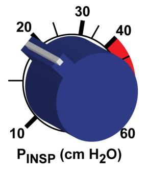
The pNeuton mini Ventilator is not intended for use
under hyperbaric pressure conditions. If used in these
conditions tidal volume delivery will significantly decrease.
Careful patient monitoring of tidal volume with a hyperbaric
compatible external spirometer is mandatory.

         The pNeuton mini Ventilator is MRI Conditional
         (see Notes section below). While tests show that
         the ventilator functions at the bore of the MRI unit,
Airon Corporation does not recommend that the ventilator
be clinically used at or within the bore of MRI scanners. A
minimum proximity of 12 inches (0.3 meter) from the bore
should be used. In addition, safe MRI practice calls for all
devices used in the proximity of an MRI scanner, including
pNeuton mini, be anchored to prevent inadvertent
movement.

    The ventilator will cease to operate properly if the
oxygen supply drops below 40 psi (280 kPa, 2.8 bar). Gas
may still flow through the ventilator from the internal
blender if the compressed air source is active, but
mechanical breaths will cease.

The Low Gas Supply Alarm will occur if the driving gas
supply drops below safe levels (40 psi, 280 kPa) or if the
difference between the two gas supply pressure is more
than 15 psi (100 kPa). The alarm activates as long as
driving gas is available or until supply pressure returns to
normal. The alarm will only activate for a very short period
of time if the gas supply abruptly ceases as can happen if
the supply gas becomes disconnected. Always insure that
the supply gas is secure and operating at the proper
pressure.

Cautions

Insure that clean, dry medical grade compressed air is
pNeuton mini Ventilator                                 2-3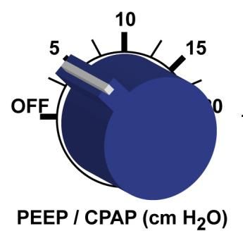
used at all times. Compressed air that is contaminated
with water or other material will damage the internal
components of the ventilator.

DO NOT obstruct or cover the holes on the left side of the
ventilator where the audible alarm is located. Doing so
may decrease the sound level of the audible alarm.

     DO NOT attempt to service the unit. Service may
only be performed by Airon Corporation authorized
engineers. The Preventative Maintenance program
requires a general service and calibration every two years.
Only original manufacturer parts and accessories should
be used.

Any attempts to modify the hardware of this device without
the express written approval of Airon Corporation will void
all warranties and liabilities.

Do not immerse the pNeuton mini Ventilator or allow any
liquid to enter the case or the oxygen / medical air inlets.
Clean as directed in Section 9, Cleaning and Maintenance.

Notes

In the USA the pNeuton mini Ventilator is a restricted
medical device intended for use by qualified medical
personnel under the direction of a physician.

During the transport of patients it is recommended that an
alternate source of ventilation be available in the event of
driving gas supply failure or ventilator malfunction.

      The ventilator will operate normally at altitudes up to
15,000 feet. Changes in altitude will not affect pressure
settings but will cause the inspiratory time to increase and
the expiratory time to decrease as altitude increases. To
pNeuton mini Ventilator                                 2-4
compensate for the effect of changing altitude on tidal
volume and respiratory rate, use an external spirometer to
verify tidal volume accuracy.
Extremely short inspiratory or expiratory time settings (0.25
seconds) may result in operational variance from the
control knob labeling. If using such short time settings,
measurement of actual delivered time is recommended.
The pNeuton mini Ventilator is MRI Conditional. Non-
clinical testing demonstrated that the pNeuton mini Infant
Ventilator is MR Conditional and can be used in
the MRI environment according to the following
conditions:
- Static magnetic field of 3-Tesla or less
- Maximum spatial gradient magnetic field of 720
Gauss/cm
IMPORTANT NOTE: This product is intended for use
within the MRI environment (e.g., in the MR system room).
It should not be utilized directly inside of the MR system
(e.g., inside of the bore of the scanner), during its
operation (i.e., scanning). As such, the assessment of
magnetic field interactions for this product specifically
involved evaluations of translational attraction and function
in relation to exposure to a 3-Tesla MR system only.
Airon recommends that users perform similar tests in their
MRI scanner prior to patient use.
Special note on the presence of latex: The components,
devices, accessories, and packaging that make up the
pNeuton mini Ventilator system do not contain any dry
natural rubber or natural rubber latex, which may cause
allergic reactions.
Special note on the presence of di (2-ethylhexyl) phthalate
(DEHP): The components, devices, accessories, and
packaging that make up the pNeuton mini Ventilator
system do not contain any phthalates which are classified
pNeuton mini Ventilator 2-5as carcinogenic, mutagenic or toxic to reproduction, of category 1 or 2, in accordance with Annex I to Directive 67/548/EEC. Additional Warnings, Cautions, and Notes are located throughout this manual. pNeuton mini Ventilator 2-6
Airon’s Medical Symbol Key

                    Consult Instructions of Use

                    CE Marked

                    Authorized Representative in European
                    Community

                    Model (Part) Number

                    Lot Number

                    Do Not Reuse

                    MRI Conditional (3 T)

                    Manufacturer

                    Manufactured Date

                    Use By Date

                    Keep Dry

                    Caution, serious injury or device
                    damage may occur by disregarding the
                    instructions accompanying this warning
                    symbol.

pNeuton mini Ventilator                                2-7
pNeuton mini Ventilator 2-8
Section 3: Controls and Patient Safety Systems

Front Panel

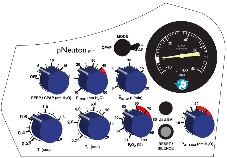
                               Pressure gauge,
                               patient circuit
                               pressure

                               Mode control, puts
                               the ventilator into
                               either the CPAP or
                               IMV + CPAP modes

pNeuton mini Ventilator                      3-1
PEEP / CPAP
control, calibrated,
range 0 to 20 cm
H2O
Peak Pressure
(PINSP) control of
mandatory breaths,
calibrated, range 15
to 60 cm H2O
Flow (VINSP) control,
sets the continuous
flow through the
patient circuit at 6, 8,
10, 15 or 20 L/min
Inspiratory Time (TI)
control, calibrated,
range 0.25 to 2.0
seconds
pNeuton mini Ventilator 3-2Expiratory Time (TE)
control, calibrated,
range 0.25 to 20.0
seconds
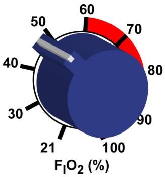
Oxygen (FIO2)
control, calibrated,
range 21% to 100%
Alarm visual
indicator
Alarm Reset /
Silence,
10 second alarm,
25 second silence
pNeuton mini Ventilator 3-3High Pressure Alarm
(PALARM) control,
range 10 to 70 cm
H2O
Side Panel
Driving Gas Input (oxygen),
requires 55 + 15 psi (380 +
100 kPa, 3.8 + 1 bar), (25
L/min minimum)
pNeuton mini Ventilator 3-4Driving Gas Input (air),
requires 55 + 15 psi (380 +
100 kPa, 3.8 + 1 bar), (25
L/min minimum)
Remote Alarm output
Patient Circuit connection,
see Section 5 for a
complete description of the
patient circuit and it's
attachment to the ventilator
Expiratory Valve connection
Proximal patient pressure
connection
pNeuton mini Ventilator 3-5Unique Device Identification (UDI)
Pursuant to the U.S. FDA Unique Device Identification
(UDI) Rule, each device must bear a UDI code. The UDI
for pNeuton mini is located under the “Serial Number:”
labeling, in plain text, on the back panel of the device. The
UDI code consists of one Device Identifier (DI) and
potentially four Production Identifiers (PI). Therefore, UDI =
DI+PI. Production identifiers are required if the information
appears on the product (box) label. The UDI on the
product (box) label appears in both plain text and machine-
readable format. The numbers in the parentheses indicate
different parts of the UDI, as applicable to the device:
(01) Device Identifier
(10) Batch / Lot Number
(11) Manufacturing / Production Date
(17) Expiration Date
(21) Serial Number
The format for Manufacturing / Production date and
Expiration date within the UDI code is: YYMMDD
• YY = tens and units of the year (e.g. 2014 = 14)
• MM = number of the month (e.g. January = 01)
• DD = number of the day (e.g. third day = 03)
• January 03, 2014 = 140103
An example UDI for the pNeuton mini is as follows:
Device Identifier = 00853678006023
Serial Number = I0000
The Device Identifier portion of the code may be entered
into AccessGUDID to obtain information about the product.
http://accessgudid.nlm.nih.gov/
pNeuton mini Ventilator 3-6Internal Patient Safety Systems
The ventilator has several internal safety systems. These
systems insure patient safety in the event of ventilator
malfunction.
High Pressure Release
The patient circuit peak pressure is adjustable using the
Peak Pressure control. This control can be set from 15 to
60 cm H2O. The factory preset value is 30 cm H2O. In
addition to this control, there is an internal safety pressure
release valve. This valve will automatically limit circuit
pressure to approximately 80 cm H2O, regardless of the
setting of the Peak Pressure control.
Anti-Suffocation System
An internal safety system will allow the patient to breathe
on his or her own in the event of ventilator malfunction. At
approximately 2 cm H2O negative pressure an internal
valve will open allowing unimpeded ambient air to enter
the patient circuit for the patient. This system is always
available to the patient, irrespective of control settings,
including PEEP / CPAP.
Low Gas Supply Pressure Alarm
When either driving gas supply pressure drops below the
safe operating pressure the visual alarm indicator will
illuminate and an internal pneumatic audible alarm will
sound. This low pressure alarm will occur when the source
gas pressure drops below 40 psi (280 kPa) or if the
difference between the two gas supply pressure is more
than 15 psi (100 kPa). The alarm will continue to sound
until all pressure has been lost in the system or when
pressure is re-established to at least 45 psi (310 kPa).
WARNING: The ventilator will cease to operate
properly if the oxygen supply drops below 40 psi (280 kPa,
2.8 bar). Gas may still flow through the ventilator from the
internal blender if the compressed air source is active, but
pNeuton mini Ventilator 3-7mechanical breaths will cease.
WARNING: The Low Gas Supply Alarm will only
activate for a very short period of time if both gas supplies
abruptly cease as can happen if both supply gases
become disconnected. Always insure that both supply
gases are secure and operating at the proper pressure.
NOTE: Always use an external oxygen monitor to insure
the desired oxygen percentage is delivered to the patient.
Disconnect Alarm
The ventilator automatically monitors patient pressure at all
times. If there is a disconnection in the patient circuit the
visual alarm indicator will illuminate and the audible alarm
will sound. The alarm activates if the circuit pressure is
less than 3 cm H2O for 10 seconds. The Disconnect alarm
may be silenced for 25 seconds by pressing the alarm
Reset / Silence button.
NOTE: Setting the CPAP level to less than 3 cm H2O
while in the CPAP mode will cause the alarm to sound
continuously.
High Patient Pressure Alarm
During mechanical ventilation the High Patient Pressure
alarm will provide an audible and visual alarm when
pressure reaches the control’s set level. The control can
be set independently of the Peak Pressure control. If it is
set less than the Peak Pressure control and patient
pressure reaches the High Pressure alarm level, it will
alarm at every breath. Setting the High Pressure alarm
control to a slightly higher level than the Peak Pressure
control will notify the operator only when there is
inadvertent high patient pressure.
pNeuton mini Ventilator 3-8Section 4: Operating Instructions
Ventilator Set-up
The following equipment is needed:
1. pNeuton mini Ventilator with breathing circuit (see
Section 5 for a list of compatible circuits.)
2. Oxygen analyzer
3. Watch
When ready:
1. Attach breathing circuit to ventilator as described in
Section 5.
2. Set the controls as follows:
a. Mode control to IMV + CPAP
b. PEEP / CPAP to Off
c. Peak Pressure (PINSP) to 30 cm H2O
d. Continuous Flow (VINSP) to 8 L/min
e. Inspiratory Time (TI) to 0.6 sec
f. Expiratory Time (TE) to 2.0 sec
g. Oxygen (FIO2) to 60%
h. High Pressure Alarm (PALARM) to 40 cm H2O
3. Occlude the patient connection or place a cap over
the patient connection to seal the circuit.
4. Attach Oxygen and Air Input on side panel of the
ventilator to high pressure gas sources and turn on
the gases.
NOTE: The ventilator will begin operation at the above
settings when the oxygen and air is turned on. The alarm
will sound. You may press the “Reset / Silence” button to
silence the alarm or wait for the unit to begin ventilating.
pNeuton mini Ventilator 4-1Operational Verification
Verification Step Acceptable Result
Range
Observe the pressure gauge. It
30 ± 3 cm
should rise to 30 cm H2O and Pass / Fail
H2O
drop to 0 cm H2O.
Count the respiratory rate with a 23 ± 3
stopwatch. Measure the number breaths per Pass / Fail
of breaths in one minute. minute
Attach an oxygen analyzer to
the output of the expiratory
valve. Using a calibrated 60% + 3% Pass / Fail
oxygen analyzer measure the
oxygen percentage.
Set the High Patient Pressure
Visual and
alarm to 20 cm H2O. The alarm
audible Pass / Fail
should activate with each
alarm
breath.
Remove the patient connection
cap and allow the breathing
10 ± 2
circuit to remain open. Using a Pass / Fail
seconds
stopwatch, measure the time
until the alarm sounds.
Disconnect one gas input with
the remaining gas source Visual and
connected to Air or Oxygen gas audible Pass / Fail
source. Verify the Low Gas alarm
Supply alarm activates.
If the ventilator has passed all the above steps it is ready for
clinical use. If the ventilator fails to pass any of the
following tests do not apply it to patients. Call your local
distributor or Airon Corporation Customer Support at 888-
448-1238 (toll free USA & Canada) or +1-321-821-9433.
Do not attempt to service the unit.
pNeuton mini Ventilator 4-2CAUTION: Do not disassemble the pNeuton mini Ventilator. No internal user replaceable parts. All service must be performed by Airon Corporation or an approved service technician. Opening the device will negate the warranty. User will be responsible for all repair costs to service the unit. Patient Ventilation The ventilator operates with the following modes: CMV - Continuous Mechanical Ventilation IMV - Intermittent Mandatory Ventilation CPAP - Continuous Positive Airway Pressure Using the Intermittent Mandatory Ventilation (IMV) mode, the ventilator provides an adjustable number of breaths per minute using the expiratory time control. The inspiratory time of these breaths is also adjustable. The patient may breathe spontaneously between ventilator breaths as desired. 1. Set the Inspiratory Time (TI) control to the appropriate level. 2. Adjust the Expiratory Time (TE) control to achieve the desired mandatory breath frequency. Refer to the Respiratory rate table on the top of the ventilator for assistance. 3. Set the Oxygen (FIO2) control to the desired FIO2. 4. Adjust the PEEP / CPAP control to the desired level. 5. Adjust the Peak Pressure (PINSP) control to the desired level by turning the control while occluding the patient circuit and observing the level of pressure generated during a mandatory breath. 6. Adjust the Continuous Flow (VINSP) control to the desired level. This sets the flow that is used for inspiration. The larger the patient, the higher flow that is needed to meet patient demand. 7. Adjust the High Pressure Alarm (PALARM) control to the pNeuton mini Ventilator 4-3
desired alarm level. This setting will determine at which
    pressure the alarm will activate. It can be set
    independent of the Peak Pressure control.
8. Set the Mode control to IMV + CPAP.
9. Turn on the gas supplies.
10. Attach the patient circuit to the patient and observe for
    appropriate ventilation. Adjust as required. External
    measurement devices may be used to verify ventilation
    parameters.
11. Observe and monitor the patient and the ventilator per
    your institution's standards. If using a portable gas
    supply, monitor the supply level to insure there is
    sufficient gas for ventilation.

The pNeuton mini functions as a pressure-limited
ventilator, as such the set inspiratory time, flow and oxygen
concentration will remain constant within the complete
range of delivered pressures.

Inspiratory and Expiratory Time Controls

The Inspiratory Time control (TI) sets the time the ventilator
delivers a mandatory breath. The range is 0.25 to 2.0
seconds. The longer the set time, the higher the tidal
volume. When the set Peak Pressure level is reached the
continuous flow through the patient circuit will be released
through the expiratory valve.

The Expiratory Time control (TE) sets the time the ventilator
does not deliver a mandatory breath. The range is 0.25 to
20.0 seconds. This control is used to set the respiratory
rate for mandatory breaths. The patient is allowed to
breathe spontaneously during this period.

Respiratory Rate Chart: estimated breaths per minute
based upon I Time and E time settings. (See chart below.)

pNeuton mini Ventilator                                 4-4
Exp Time (sec)
Insp Time
(sec) 0.25 2 4 6 10 15
0.25 120 27 14 10 6 4
0.4 92 25 14 9 6 4
0.6 71 23 13 9 6 4
0.8 57 21 13 9 6 4
1.0 48 20 12 9 5 4
1.2 41 19 12 8 5 4
1.4 36 18 11 8 5 4
1.6 32 17 11 8 5 4
1.8 29 16 10 8 5 4
2.0 27 15 10 8 5 4
The patient’s breathing efforts cannot affect the timing of
mandatory breaths. The mandatory breaths are started
when the set expiratory time ends. There is no
synchronization of patient effort with the start of mandatory
breaths. At the end of the expiratory time the ventilator will
switch to inspiration and provide a breath for the set
inspiratory time at the set peak pressure.
Peak Pressure and Continuous Flow Controls
The Peak Pressure control (PINSP) sets the maximum
pressure that will be generated in the patient circuit. The
range is 15 to 60 cm H2O. This is a pressure limiting
system. When the pressure is reached during inspiration
the continuous flow through the patient circuit will then
escape out the exhalation valve instead of going into the
patient.
The Continuous Flow control (VINSP) sets the level of flow
through the patient circuit. This is a continuous flow that is
maintained at all times. The flow settings are 6, 8, 10, 15
and 20 L/min.
pNeuton mini Ventilator 4-5The combination of the Inspiratory Time, Peak Pressure and Flow settings determine the tidal volume delivered. The time of inspiration and the flow through the circuit determines tidal volume as long as the pressure level is not reached. Once the pressure level is reached, flow is then diverted out the exhalation valve and delivered volume to the patient stops. See a complete description of the relationship of these controls to tidal volume delivery in Section 7. PEEP / CPAP Control The PEEP / CPAP control sets the level of PEEP during mandatory ventilation and CPAP during spontaneous breathing. The range is 0 to 20 cm H2O. This is a continuous flow system using the expiratory valve to control the pressure level. It functions during all ventilator modes. Oxygen Control The Oxygen Control (FIO2) sets the level of oxygen delivered to the patient. The range is 21% to 100%. The ventilator uses an internal oxygen / air mixing system which provides the continuous flow into the patient circuit. See Section 7 for a complete description of this system. It is recommended that an external oxygen analyzer always be used to verify oxygen delivery. High Pressure Alarm The High Patient Pressure alarm (PALARM) will provide an audible and visual alarm when pressure reaches the control’s set level. The range is 10 to 70 cm H2O. The control can be set independently of the Peak Pressure control. If it is set less than the Peak Pressure control and patient pressure reaches the alarm level, it will alarm at pNeuton mini Ventilator 4-6
every breath. Setting the High Pressure alarm control to a
slightly higher level than the Peak Pressure control will
notify the operator only when there is inadvertent high
patient pressure.

The alarm system provides a remote alarm output on the
left side of the ventilator. Use the Airon Remote Alarm (Part
number 21031) to provide a remote audible and visual
indication of active alarm conditions.

Disconnect Alarm

The ventilator has a patient circuit disconnect alarm system.
This system cannot be turned off. If a circuit disconnect is
sensed, the visual indicator on the front panel will illuminate
and the audible alarm will sound.

The alarm will activate as soon as a gas source is turned on
to the ventilator. You may silence the alarm for 25 seconds
by pressing the Reset / Silence button. Attaching the
ventilator to a patient and starting ventilation will
automatically reset the alarm system and turn off the
audible and visual indicators.

A patient circuit disconnect is sensed if the pressure in the
patient circuit is less than 3 cm H2O for 10 seconds.
Mandatory breaths of 3 cm H2O or greater during the 10
second window will reset the alarm to wait for the next
breath. When PEEP / CPAP is turned on and set for at
least 3 cm H2O no patient breaths are required to satisfy the
alarm system.

NOTE: Setting the CPAP level to less than 3 cm H2O while
in the CPAP mode will cause the alarm to sound
continuously.

The alarm system can be momentarily silenced by pressing
the Reset / Silence button on the front panel. Pressing this

pNeuton mini Ventilator                                 4-7
button turns off the visual and audible indicators for 25
seconds. Each time the Reset / Silence button is pressed;
the alarm system restarts the 25 second silence time delay.
This delay is NOT cumulative. In other words, repeatably
pressing the Reset / Silence button will not increase the
silence time by more than 25 seconds.

The alarm system provides a remote alarm output on the
left side of the ventilator. Use the Airon Remote Alarm (Part
Number 21031) to provide a remote audible and visual
indication of active alarm conditions.

Hypobaric (Altitude) Operation

The ventilator will operate normally at altitudes up to 15,000
feet. Changes in altitude will not affect pressure settings.
However, delivered inspiratory time increases and
expiratory time decreases with increasing altitude. This is
due to lower barometric pressure than the ventilator’s
calibration at standard sea level.

To compensate for the effect of changing altitude on
inspiratory and expiratory time, use a stopwatch to verify
ventilation timing accuracy. Adjust the inspiratory and
expiratory time controls to the desired value as measured
by the stopwatch rather than the markings on the control
panel.

pNeuton mini Ventilator                                4-8
Section 5: Patient Circuit

Infant and Pediatric Circuits

The patient circuits designed for use with the pNeuton
mini Ventilator are:
   • Neonatal to infant patients - part number 58031, 10
       mm internal diameter, 6 ft. (1.8 m) length
       disposable patient circuit. Box of 15.
           o Use 6 or 8 L/min flow setting with this circuit.
           o Compression volume = 0.1 ml per cm H2O
   • Neonatal to infant patients - part number 58201, 10
       mm internal diameter, 8 ft. (2.4 m) length
       disposable patient circuit. Box of 10.
           o Use 6 or 8 L/min flow setting with this circuit.
           o Compression volume = 0.1 ml per cm H2O
   • Pediatric patients – part number 58035, 15 mm
       internal diameter, 6 ft. (1.8 m) length disposable
       patient circuit. Box of 15.
           o Use 8, 10, 15 or 20 L/min flow setting with
               this circuit.
           o Compression volume = 0.5 ml per cm H2O

     WARNING: Patient circuits other than the Airon
circuits listed above will alter the ventilator's CPAP / PEEP
characteristics and / or expiratory flow resistance. They
should NOT be used and may lead to patient harm.

     WARNING: Do not use air filters on the expiratory
port of the patient circuit except those provided by Airon
Corporation. Some filters may alter the ventilator's CPAP /

pNeuton mini Ventilator                                 5-1
PEEP characteristics and / or expiratory flow resistance.
They should NOT be used and may lead to patient harm.
Ventilator Connection
The patient circuit must be attached to the ventilator
properly. Incorrect attachment could result in failure to
provide adequate ventilation.
The main breathing hose
(22 mm) is connected to the
“Patient Connection” port.
The small tubing (3 mm)
connects the expiratory
valve to the “Expiratory
Valve” barb connection
The small blue tubing (4
mm) connects the proximal
patient port of the circuit to
the blue “Proximal
Pressure” barb connection
WARNING: The proper attachment of the circuit’s
small tubing to the Expiratory Valve and Proximal Pressure
connections of the ventilator are very important.
Connecting the tubes to the wrong connectors will cause
the ventilator to malfunction and not provide ventilation.
DO NOT cross connect these tubes.
NOTE: The Airon patient circuit is a single use, disposable
device. Cleaning, reprocessing and / or reuse of this
pNeuton mini Ventilator 5-2device is not recommended. The circuit and all
components are sold clean and non-sterile.
Single-Use only Medical Devices/Accessories
How do I know if a device is Single-Use?
This symbol will be identified on the packaging and
User’s Manual of the device.
What does Single-Use mean?
Do not reuse. A single-use device is used on an individual
patient during a procedure, such as transport ventilation,
and then discarded. It is not intended to be reprocessed
and used again, even on the same patient.
What is the concern with reused device labeled Single-
Use?
The use of reprocessed devices may present serious
incidents relating to the health and safety of patients and
healthcare professionals. Reuse can be unsafe because
of risk of:
• Cross-infection – inability to clean and
decontaminate due to design, device components
are not manufactured for disassembly and
reassembly
• Endotoxin reaction – excessive bacterial
breakdown products, which cannot be adequately
removed by cleaning
• Patient injury – device failure from reprocessing or
reuse because of fatigue or material alteration
• Chemical burns or sensitization – residues from
chemical decontamination agents on materials that
can absorb chemicals
NOTE: If you reuse a single-use device you may be
legally liable for the safe performance of the device.
pNeuton mini Ventilator 5-3pNeuton mini Ventilator 5-4
Section 6: Accessories

Accessories have been compiled to add safety and an
ease of operation and training.
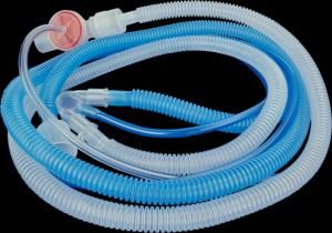
   - Patient circuits
   - CPAP interfaces
   - MRI environment

                               Neonatal/infant patient
                               circuit- Box of 15 (Box of 10).
                               Disposable, single patient
                               use. 10mm ID, 6 foot (1.8m)
                               or 8 foot (2.4m) length.
                               SAFETY NOTE: Only Airon
                               manufactured patient
                               breathing circuits are
                               approved for use with
                               pNeuton ventilators.

                               Child /pediatric patient
                               circuit – Box of 15.
                               Disposable, single patient
                               use. 15mm ID, 6 foot (1.8m)
                               length. SAFETY NOTE: Only
                               Airon manufactured patient
                               breathing circuits are
                               approved for use with
                               pNeuton ventilators.

                               miniFlow nCPAP Patient
                               Interface – Box of 20. For
                               use with the pNeuton mini.

                               miniFlow Start-up Kit –
                               Small. Disposable, single
                               patient use. Includes 5
                               miniFlow interfaces, 3 Small
                               nasal prongs, 2 masks, and 3
                               bonnets.

pNeuton mini Ventilator                               6-1
miniFlow Start-up Kit -
Large. Disposable, single
patient use. Includes 5
miniFlow interfaces, 3 Large
nasal prongs, 2 masks, and 3
bonnets.
miniFlow Nasal Prongs –
Nasal prongs for use with
miniFlow system. Box of 10
single use, disposable nasal
prongs.
miniFlow Nasal Mask –
Nasal mask for use with
miniFlow system. Box of 10
single use, disposable nasal
masks.
miniFlow Bonnet - Head
Bonnet for use with miniFlow
system. Box of 10 single use,
disposable bonnets.
miniFlow Attachment strip
for bonnets – Attachment
strips for use with miniFlow
system. Box of 10 single use,
disposable strips.
Test Lung, infant – A rigid
wall Test Lung is ideal to test
and demonstrate the
performance of the pNeuton
mini. Spontaneous breaths
can only be properly
simulated using a rigid wall
test lung.
pNeuton mini Ventilator 6-2MRI compatible Mobile
Stand, mini – The Mobile
Stand is a 3 foot, 9 inch (1.2
m) tall, MRI compatible stand
designed to hold the pNeuton
mini ventilator. The five
wheeled stand uses large 3
inch (7.6 cm) wheels to aid in
stability and ease of
movement. Four “E” size
cylinders (2 medical air, 2
oxygen) can be securely
mounted on the stand. The
ventilator attaches to the
stand using a mounting plate
which allows the user to slide
the ventilator on and off the
stand for transport.
Pole Mount – The mini Pole
Mount will allow the ventilator
to be mounted to standard
horizontal or vertical poles up
to 1.25″ (3 cm). The mount
provides a sturdy support
during patient transport. The
ventilator attaches to the
mount using a mounting plate
which allows the user to slide
the ventilator on and off the
mount.
Remote Alarm
Respironics Model 1118941
- Allows the user to attach a
remote alarm to the pNeuton
Ventilator. Great for the MRI
control room.
pNeuton mini Ventilator 6-3Remote Alarm Cables
MRI compatible BNC cables
to attach the remote alarm to
the pNeuton Ventilator
50 foot (15 m) cable
100 foot (30 m) cable
Oxygen Regulator – A MRI
compatible high pressure
oxygen regulator for D / E
size oxygen tanks.
Medical Air Regulator – A
MRI compatible high pressure
medical air regulator for D / E
size tanks.
Manifold System - A 3-way
manifold that connects to the
mobile stand and allows for
the seamless use of two
oxygen cylinders and external
oxygen supply to provide
continuous power to the
pNeuton ventilator. Both
systems include 1 oxygen and
1 medical air manifold, 3 x 18″
each high pressure air and
oxygen hoses and 1 x 10′
each high pressure air and
oxygen hoses. The standard
manifold also includes 2 each
oxygen and medical air
regulators.
High Pressure Oxygen
Hose - DISS Female both
ends, MRI compatible. (Note:
ISO color hose available)
High Pressure Medical Air
Hose - DISS Female both
ends, MRI compatible.
pNeuton mini Ventilator 6-4Oxygen Cylinder, E Size
– A 600 liter green oxygen
cylinder with yoke stem valve
Medical Air Cylinder, E Size
– A 600 liter yellow medical
air cylinder with yoke stem
valve
pNeuton mini Ventilator 6-5pNeuton mini Ventilator 6-6
Section 7: Theory of Operation

The pNeuton mini is a pneumatic ventilator based upon
the Intermittent Mandatory Ventilation (IMV) principle. As
such, adjustable inspiratory timed breaths are delivered to
the patient between which the patient may breathe
spontaneously. This section describes how the ventilator
operates.

Further information on the ventilator's theory of operation,
including circuit diagrams, parts lists, and calibration
instructions are available from Airon Corporation to
properly trained service personnel.

Pneumatic System Diagram

pNeuton mini Ventilator                                 7-1
Pneumatic System Description

The major components of the pneumatic system and the
control of gas flow through the ventilator are as follows:

    1. High pressure gases, oxygen and medical grade
       compressed air enters the ventilator and are filtered
       (5 micron) and reduced to a lower working pressure
       (40 psi, 280 kPa, 2.8 bar).
    2. Both gases go into a high quality oxygen blender
       where they are mixed per the FIO2 control setting.
       This blender provides accurate gas mixing + 3%
       throughout the operating range of the ventilator.
    3. The output of the oxygen blender goes to the Flow
       (VINSP) control. This device controls the flow of
       mixed gas to the patient circuit connection.
    4. The timing circuit is separately driven by the
       oxygen source gas and uses two precision control
       valves to control inspiratory and expiratory time.
       These valves charge (or reduce) pressure to a
       pneumatic timing cartridge. This timing cartridge
       turns on or off the gas supply to the Peak Pressure
       control system.
    5. The Peak Pressure control system sends an
       adjustable pressure to the patient circuit expiratory
       valve. The pressure in this system determines the
       peak pressure that can be generated in the patient
       circuit.
    6. The adjustable PEEP / CPAP system directs a
       pressure signal to the expiratory valve to generate
       the PEEP and CPAP levels in the circuit.
    7. The circuit pressure measured at the proximal
       patient port is directed to the pressure gauge and
       the High Pressure Alarm control. If patient
       pressure exceeds the control setting a pneumatic
       signal is sent to activate the audible and visual
       alarm system. A small amount of gas continuously
       flows down the patient pressure line to insure it
       remains open. The gas is at the same oxygen
       concentration at the oxygen control.

pNeuton mini Ventilator                                7-2
8. The proximal patient pressure signal is also sent to
the patient disconnect alarm system. See the
description later in this section for information on
how the alarm functions.
Management of Patient Tidal Volume through the
Inspiratory Time, Flow and Peak Pressure
Controls
The combination of the Inspiratory Time, Peak Pressure
and Flow settings determine the tidal volume delivered to
the patient. There is no set or guaranteed tidal volume.
The tidal volume the patient actually receives can vary
breath to breath due to many factors including the patient’s
lung compliance / resistance and leaks around the patient
interface.
The time of inspiration and the flow through the circuit is
the basic determination of tidal volume (ml). During
inspiration the ventilator closes the expiratory valve and
the continuous flow is directed into the patient’s lungs.
The time of inspiration multiplied by the flow equals the
tidal volume. The following chart shows the range of tidal
volume delivery based on the available control setting:
Continuous Flow (L/min)
Insp Time (sec) 6 8 10 15 20
0.25 25 33 42 63 83
0.40 40 53 67 100 133
0.60 60 80 100 150 200
0.80 80 107 133 200 267
1.00 100 133 167 250 333
1.20 120 160 200 300 400
1.40 140 187 233 350 467
1.60 160 213 267 400 533
1.80 180 240 300 450 600
2.00 200 267 333 500 667
The above table assumes that all of the flow from the
pNeuton mini Ventilator 7-3ventilator goes to the patient’s lungs. This is seldom the case in neonatal and infant ventilation. Gas is often lost around the endotracheal tube or mask interface. Gas can also be lost due to pressure limitation of the exhalation valve. The Peak Pressure control is used to set the highest pressure delivered to the patient. When this pressure in the circuit is reached, all flow during the inspiratory time is then diverted out the exhalation valve. This diverted flow does not contribute to delivered tidal volume. The Peak Pressure control can be tested by occluding the patient port of the patient circuit during a mandatory breath. During the breath the pressure will rapidly raise to the set peak pressure. The level can be adjusted by turning the Peak Pressure control until the desired peak pressure is achieved. As when using any mechanical ventilator, careful attention to detail is required. It is suggested that independent validation of tidal volume and rate be performed using external spirometers and timing devices. CPAP System The ventilator's internal CPAP system provides gas for spontaneous breathing at adjustable CPAP pressures up to 20 cm H2O. This is a simple continuous flow system. The patient may inhale at any flow rate needed. If the patient’s spontaneous inspiratory flow is greater than the set continuous flow, inspiratory pressure may decrease. Adjusting the continuous flow to meet the patient’s inspiratory demand will decrease work of breathing. The PEEP / CPAP control is calibrated to the dynamics of Airon Corporation disposable patient circuit. Using this circuit will insure proper operation and the full 0 to 20 cm H2O PEEP / CPAP range. pNeuton mini Ventilator 7-4
Oxygen Delivery System

The pNeuton mini ventilator uses a sophisticated oxygen
blender to mix oxygen and air for delivery to the patient.
This blender requires both compressed oxygen and
medical grade air for proper operation. The ventilator
should not be used if either gas source is not available.

The required input pressure for each gas is 55 + 15 psi
(380 + 100 kPa or 3.8 + 1 bar). The gas source must be
able to maintain the required pressure with flow up to 25
L/min. If the supply pressure decreases below the
required pressure due to flow demand, the low gas supply
alarm will activate.

The FIO2 control sets the oxygen / air percent mixture
delivered to the patient. The continuous flow rate of this
oxygen mixture into the patient circuit is controlled by the
Flow (VINSP) control. The accuracy of the blender is 3%. If
the low gas supply alarm is activated, the delivered oxygen
will not be accurate.

Large variance between the pressures of either gas source
may affect accuracy of the oxygen blender. The internal
pressure regulators reduce both gases to 40 psi for use by
the blender. As long as both gases are at the minimum
pressure or above the mixing system will operate properly.
However, if the gas pressures differ by 15 psi (100 kPa or
1 bar) or more then the accuracy may be affected and the
alarm system will activate.

The operation of the internal pneumatic control system
does not use the output of the blender. All pneumatics are
operated from oxygen only. This insures proper operation,
regardless of the percent oxygen being delivered to the
patient. If the oxygen supply pressure decreases below
the required level, the pneumatic system may malfunction.

pNeuton mini Ventilator                               7-5
WARNING: Never operate the ventilator without
proper oxygen and air gas supplies at the required
pressure.

    The ventilator will cease to operate properly if the
oxygen supply drops below 40 psi (280 kPa, 2.8 bar). Gas
may still flow through the ventilator from the internal
blender if the compressed air source is active, but
mechanical breaths will cease.

Factors Effecting the Operating Time from Tanks
There are several factors that affect the length of time the
ventilator will operate from oxygen / air cylinders. The
ventilator uses very little gas for its own operation (less
than 3 L/min) and is not a major factor in oxygen tank
consumption. The major factors are:
• Volume of oxygen in the oxygen and air tanks
• Flow setting
• CPAP setting
• Position of the FIO2 control
• Mode selected

NOTE: Always use full oxygen and air tanks before the
start of any transport. The calculation of any expected run
time becomes unreliable as tank pressure is reduced.

The relative amount of oxygen and air used is dependent
on the FIO2 setting. At 60% oxygen, the oxygen and air
tanks will be depleted at the same rate. Lower
concentrations of oxygen will result in more air used than
oxygen. Higher then 60% will result in more oxygen used
then air. Also, operation of the IMV + CPAP mode will
result in slight greater consumption of oxygen and air, due
to the oxygen use by the pneumatic timing system.

pNeuton mini Ventilator                                 7-6
The following table shows the expected operating times
under the following condition:
• Full “E” size tanks (USA – 660 liters pressurized)
• IMV + CPAP mode
• Inspiratory time – 0.6 seconds
• Expiratory time – 2.0 seconds
• CPAP – 5 cm H2O
Flow 21% 60% 100%
6 L/m 100 min 100 min 60 min
10 L/m 60 min 80 min 45 min
15 L/m 40 min 60 min 30 min
MRI Compatibility
The ventilator was engineered and built to be MRI
compatible. Testing in a MRI scanner has shown that the
scanner does not affect the ventilator’s performance. The
ventilator does not generate artifact, RF noise, or other
deleterious effects on the operation of the MRI scanner or
it's production of an image. In addition, due to pNeuton
mini ventilator components, heating of the ventilator does
not occur during scanning.
Testing for MRI compatibility was done following ASTM
MRI safety standards F2052 – 06e1 and F2119 – 07. The
MRI scanner used has the following maximum
performance levels:
• Static field strength - 3 Tesla
• Spatial field gradient - 720 G/cm
The scanner used for testing was an active shielded
system. The ventilator was placed in the position of
maximum field strength and maximum spatial gradient.
The standard patient circuit (Airon part number 58031) was
used. A standard imaging sequence with a maximum
scanning time of 5 minutes was used.
pNeuton mini Ventilator 7-7The pNeuton mini ventilator meets testing
requirements for use within the Magnetic
Resonance Environment with a conditional
marking for safety.
NOTE: Airon recommends that users perform the above
referenced tests in their MRI scanner prior to patient use.
WARNING: While tests show that the ventilator
functions at the bore of the MRI unit, Airon Corporation
does not recommend that the ventilator be clinically used
at or within the bore of MRI scanners. A minimum
proximity of 12 inches (0.3 meter) from the bore should be
used. In addition, safe MRI practice calls for all devices
used in the proximity of a MRI scanner be anchored to
prevent inadvertent movement.
High Pressure Alarm
The High Patient Pressure alarm (PALARM) will provide an
audible and visual alarm when pressure reaches the
control’s set level. The range is 10 to 70 cm H2O. The
control can be set independently of the Peak Pressure
control. If it is set less than the Peak Pressure control and
patient pressure reaches the alarm level, it will alarm at
every breath. Setting the High Pressure alarm control to a
slightly higher level than the Peak Pressure control will
notify the operator only when there is inadvertent high
patient pressure.
The alarm system uses the proximal patient pressure
signal. It is inline with the pressure gauge so that the
pressure shown on the gauge is the same as the alarm
system uses. The sensing line to the patient wye is
constantly flushed by a very small flow of oxygen to
maintain patency.
pNeuton mini Ventilator 7-8This alarm is part of the ventilator’s alarm system and is connected to the remote alarm output. This remote alarm output provides a passive, non-electrically charged remote alarm signal on the rear of the ventilator. The remote output uses a normally closed signal output with a resistance of 51K Ohms. When an alarm occurs, the signal output opens to infinite resistance. This is a passive remote alarm output that does not provide its own electrical signal. Use the Airon Remote Alarm (Part number 21031) to provide a remote audible and visual indication of active alarm conditions. Disconnect Alarm The ventilator has an internal patient circuit disconnect alarm system. This system cannot be turned off. If a circuit disconnect is sensed, the visual indicator on the front panel will illuminate and the audible alarm will sound. This alarm system is always on and monitoring pressure in the circuit. Whenever circuit pressure drops below 3 cm H2O an independent pressurized capacitance begins to drop in pressure. If a return to at least 3 cm H2O pressure does not occur within 10 seconds the pressure in the capacitance drops low enough to activate the audible and visual alarm system. The alarm will activate as soon as an oxygen source is turned on to the ventilator. Attaching the ventilator to a test lung or the patient and starting ventilation or CPAP will automatically reset the alarm system and turn off the audible and visual indicators. The alarm system can be momentarily silenced by pressing the Reset / Silence button on the front panel. Pressing this button turns off the visual and audible indicators for 25 seconds. Each time the Reset / Silence pNeuton mini Ventilator 7-9
button is pressed; the alarm system restarts the 25 second
silence time delay. This delay is NOT cumulative. In other
words, repeatably pressing the Reset / Silence button will
not increase the silence time by more than 25 seconds.

The alarm system is entirely pneumatic and uses no
electricity. A series of valves and pneumatic capacitances
provide the sensing network. Due to the nature of this
system, a minimum CPAP of 3 cm H2O is required. If
CPAP is set for less than 3 cm H2O and mandatory
breaths are not being provided, the alarm system will
activate.

This alarm is also connected to the remote alarm system
described above. When a disconnect alarm is activated, a
remote alarm signal is sent. Use the Airon Remote Alarm
(Part number 21031) to provide a remote audible and
visual indication of active alarm conditions.

Low Gas Supply Alarm

The Low Gas Supply Alarm will occur if the driving gas
supply (Air or Oxygen) drops below safe levels (40 psi, 280
kPa, 2.8 bar). Supply pressures are monitored
independently so that if only one supply is low, the alarm
will still activate. The alarm activates as long as driving
gas is available or until the supply pressure returns to
normal.

When operating from cylinders the ventilator will gradually
use up the gas and tank pressures will fall. Once one of
the cylinders reach approximately 500 psi (35 bar), most
portable tank regulators will start to decrease pressure to
the ventilator during mandatory breaths. As this happens
the at Low Gas Supply Alarm will sense the decreased
pressure and begin to intermittently alarm each time the
pressure drops during inspiration. As pressure in the
cylinder falls to lower values, the amount of time the
regulator is delivering low pressure increases and the

pNeuton mini Ventilator                               7 - 10
alarm sounds longer. Eventually the regulator is unable to
maintain pressure and the alarm will sound continuously
until all gas in all cylinders is used.

Note: The Low Gas Supply Alarm will only activate for a
very short period of time if the gas supply abruptly ceases.
This can occur if operating from a wall source and the gas
supply hoses are disconnected from the gas supply outlet.
In fact, the Low Gas Supply Alarm may not sound at all
when the ventilator is disconnected from a wall source.
This is because all gas in the high pressure hose
immediately exits out from where the hose was connected
to the outlet and there is no gas pressure to power the
ventilator’s alarm. When using the ventilator on a patient
always insure that the supply gas is secure and operating
at the proper pressure.

A differential pressure gas supply alarm is included to
ensure proper performance and calibration of the internal
air / oxygen blender. The alarm condition will trigger if the
pressure differential between the air and oxygen sources
to the blender is approximately 18-22 psi.

pNeuton mini Ventilator                                 7 - 11
pNeuton mini Ventilator 7 - 12
Section 8: Troubleshooting

This troubleshooting guide lists common problems that
may be encountered and possible solutions. If none of the
corrective actions seem to work, contact Airon Corporation
or your distributor.

    Indication                 Meaning           Corrective Action
 Ventilator does          Missing or             Check gas source,
 not operate – no         insufficient driving   55 psi (380 kPa) at
 patient ventilation      gas supply             25 L/min is required
                          Patient circuit        Reconnect patient
                          disconnection          circuit
                          Internal malfunction   Send ventilator for
                                                 service
 Ventilator seems         Peak Pressure          Increase Peak
 to “want” to             control set too low    Pressure control
 operate, but no
 breaths are
 generated
                          Expiratory Time (TE)   Decrease Expiratory
                          set too long           Time
                          Proximal pressure      Ensure tubing is
                          line disconnected      properly connected
                          Expiratory valve       Ensure tubing is
                          drive line             properly connected
                          disconnected
                          Expiratory Valve is    Replace patient
                          malfunctioning         circuit
                          Insufficient driving   Check gas source,
                          gas supply             55 psi (380 kPa) at
                                                 25 L/min is required
                          Internal malfunction   Send ventilator for
                                                 service
 Ventilator               CPAP may be            Check CPAP control
 appears to be            turned on high
 stuck in
 inspiration
                          Internal malfunction   Send ventilator for
                                                 service

pNeuton mini Ventilator                                        8-1
You can also read


