Maple Armor FW106, FW106C - Fire Alarm Control Panel - Installation and Operation Manual
←
→
Page content transcription
If your browser does not render page correctly, please read the page content below
Maple Armor

FW106, FW106C
Fire Alarm Control Panel

Installation and Operation Manual
                               DOC‐FW106‐UM‐R1.6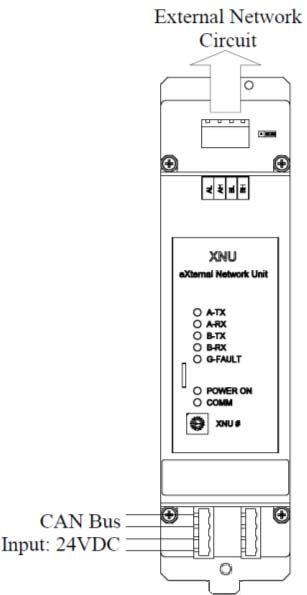
Installation and Operation Manual

TABLE OF CONTENTS
Control Panel Limitations ................................................................................................................................................... 1
Agency Listings, Approvals ................................................................................................................................................. 2
    Underwriters Laboratories (UL/ULC) .......................................................................................................................... 2
          Requirements for All Installations ...................................................................................................................... 2
          Requirements for Local Protected Fire Alarm Systems ...................................................................................... 2
Overview ............................................................................................................................................................................ 3
    FW106/FW106CFire Alarm Control Panel .................................................................................................................. 3
    Board Assembly Diagram ........................................................................................................................................... 5
    FW106/FW106C Configuration .................................................................................................................................. 6
    Specifications and Features ........................................................................................................................................ 7
    System Components ................................................................................................................................................... 8
          Components Overview ....................................................................................................................................... 8
          AMI ..................................................................................................................................................................... 9
          PTU ................................................................................................................................................................... 10
          PCU ................................................................................................................................................................... 11
          ALU ................................................................................................................................................................... 12
          NOU .................................................................................................................................................................. 13
          ROU................................................................................................................................................................... 14
          XNU................................................................................................................................................................... 15
          Battery .............................................................................................................................................................. 15
INSTALLATION ................................................................................................................................................................... 16
    Cautions .................................................................................................................................................................... 16
    Control Panel Location ............................................................................................................................................. 16
    Control Panel Installation Notice .............................................................................................................................. 16
    FW106/FW106C Mounting Space ............................................................................................................................ 17
    FW106/FW106C Installation Size ............................................................................................................................. 18
    Cabinet Mounting..................................................................................................................................................... 19
    Remove Knock‐Outs ................................................................................................................................................. 19
    Battery Installation ................................................................................................................................................... 21
    Unit Address Setting ................................................................................................................................................. 22
SYSTEM WIRING ............................................................................................................................................................... 23
    Wiring Notes ............................................................................................................................................................. 23
    Power Limiting .......................................................................................................................................................... 23
          Wiring Entering the Enclosure .......................................................................................................................... 23
          Wiring Separation ............................................................................................................................................. 24
    Power Supply Wiring ................................................................................................................................................ 24
          AC Connection .................................................................................................................................................. 24
          Battery Connection ........................................................................................................................................... 27
    Addressable Loop Circuit Wiring .............................................................................................................................. 28
          Addressable Loop Circuit Wiring – Class A ....................................................................................................... 28
          Addressable Loop Circuit Wiring – Class B ....................................................................................................... 29

                                                                                           I
Installation and Operation Manual
Notification Appliance Circuit Wiring ....................................................................................................................... 30
Notification Appliance Circuit Wiring – Class A ................................................................................................ 30
Notification Appliance Circuit Wiring – Class B ................................................................................................ 31
Relay Output Circuit Wiring ...................................................................................................................................... 32
External Network Circuit Wiring ............................................................................................................................... 33
External Network Circuit Wiring ‐ Class B ......................................................................................................... 33
Auxiliary Power Output Wiring................................................................................................................................. 34
Communication Port Connection ............................................................................................................................. 34
System Checkout ...................................................................................................................................................... 36
Before Turning the Power ON........................................................................................................................... 36
Power‐up Procedure ......................................................................................................................................... 36
Troubleshooting........................................................................................................................................................ 37
Circuit Trouble .................................................................................................................................................. 37
Ground Fault ..................................................................................................................................................... 37
Battery Trouble ................................................................................................................................................. 37
Common Trouble .............................................................................................................................................. 37
Operation ......................................................................................................................................................................... 38
Status handling ......................................................................................................................................................... 38
Standby Condition ............................................................................................................................................ 38
Alarm Conditions .............................................................................................................................................. 38
Trouble Conditions ........................................................................................................................................... 39
Supervisory Conditions ..................................................................................................................................... 41
Device, Appliance Handling ...................................................................................................................................... 42
NAC Activation and Silence .............................................................................................................................. 42
Device Supervision ........................................................................................................................................... 42
Detector Monitor.............................................................................................................................................. 42
Manual Station Response ................................................................................................................................. 43
Drift Compensation .......................................................................................................................................... 43
Alarm Verification ............................................................................................................................................. 43
Positive Alarm Sequence (PAS) ......................................................................................................................... 44
Two‐Stage ......................................................................................................................................................... 45
By‐pass.............................................................................................................................................................. 45
Auto addressing ................................................................................................................................................ 45
Event History ............................................................................................................................................................ 46
LED, Buzzer, Buttons ................................................................................................................................................. 47
LEDs Operation ................................................................................................................................................. 47
Buzzer Operation .............................................................................................................................................. 48
Button Operation.............................................................................................................................................. 49
LCD Display ....................................................................................................................................................... 50
Lamp Test .......................................................................................................................................................... 50
Configuration and Maintenance............................................................................................................................... 51
PC Configuration ............................................................................................................................................... 51
Control Panel Access Control............................................................................................................................ 51
Control Panel Configuration ............................................................................................................................. 52
Appendix‐A: Compatible Devices ..................................................................................................................................... 57
IIInstallation and Operation Manual
Devices for Addressable Loop Circuits...................................................................................................................... 57
Appliances for Notification Appliance Circuits ......................................................................................................... 57
Appendix‐B: Wire Selection Guide ................................................................................................................................... 58
SLC Wire Selection Guide ......................................................................................................................................... 58
NAC Wire Selection Guide ........................................................................................................................................ 59
Annunciator Wire Selection Guide ........................................................................................................................... 59
Appendix‐C: Quantities of Notification Appliances .......................................................................................................... 60
Appendix‐D: Battery Calculations ..................................................................................................................................... 61
Total System Currents Calculations .......................................................................................................................... 61
Battery Capacity ....................................................................................................................................................... 63
Appendix‐E: Glossary and Acronyms ................................................................................................................................ 64
IIIInstallation and Operation Manual
List of Figures
Figure 1 FW106/FW106C Control Panel ............................................................................................................................. 3
Figure 2 Assembly Diagram ................................................................................................................................................ 5
Figure 3 Assembly Diagram (Inside) ................................................................................................................................... 5
Figure 4 AMI (Front) ........................................................................................................................................................... 9
Figure 5 AMI (Back) .......................................................................................................................................................... 10
Figure 6 PTU ..................................................................................................................................................................... 10
Figure 7 PCU ..................................................................................................................................................................... 11
Figure 8 ALU ..................................................................................................................................................................... 12
Figure 9 NOU .................................................................................................................................................................... 13
Figure 10 ROU................................................................................................................................................................... 14
Figure 11 XNU ................................................................................................................................................................... 15
Figure 12 FW106/FW106C Enclosure Mounting Size ....................................................................................................... 17
Figure 13 FW106/FW106C Installation Size ..................................................................................................................... 18
Figure 14 Wiring Separation ............................................................................................................................................. 20
Figure 15 Battery Installation ........................................................................................................................................... 21
Figure 16 Unit Address Switch .......................................................................................................................................... 22
Figure 17 Wiring Terminals Location ................................................................................................................................ 24
Figure 18 AC Power Supply Wiring ................................................................................................................................... 25
Figure 19 Ground Wiring .................................................................................................................................................. 25
Figure 20 AC Power Supply Wiring (Terminal) .................................................................................................................. 26
Figure 21 Battery Connection ........................................................................................................................................... 27
Figure 22 Addressable Loop Circuit Wiring – Class A ....................................................................................................... 28
Figure 23 Addressable Loop Circuit Wiring – Class B ....................................................................................................... 29
Figure 24 Notification Appliance Circuit Wiring – Class A ................................................................................................ 30
Figure 25 Notification Appliance Circuit Wiring – Class B ................................................................................................ 31
Figure 26 Relay Output Circuit Wiring .............................................................................................................................. 32
Figure 27 External Network Circuit Wiring ‐ Class B ......................................................................................................... 33
Figure 28 Auxiliary Power Output Wiring ......................................................................................................................... 34
Figure 29 AMI ................................................................................................................................................................... 35
Figure 30 LCD (Standby) ................................................................................................................................................... 38
Figure 31 LCD (Trouble) .................................................................................................................................................... 39
Figure 32 Alarm Verification ............................................................................................................................................. 43
Figure 33 Positive Alarm Sequence .................................................................................................................................. 44
Figure 34 Two‐Stage Alarm............................................................................................................................................... 45
IVInstallation and Operation Manual
List of Tables
Table 1 FW106/FW106C Module Units .............................................................................................................................. 6
Table 2 FW106/FW106C Control Panel Specifications ....................................................................................................... 7
Table 3 System Components .............................................................................................................................................. 8
Table 4 Battery Space ....................................................................................................................................................... 21
Table 5 Unit Address Range .............................................................................................................................................. 22
Table 6 Circuit Trouble ...................................................................................................................................................... 37
Table 7 Trouble Event Type ............................................................................................................................................... 40
Table 8 LEDs Operation..................................................................................................................................................... 47
Table 9 Buttons Function .................................................................................................................................................. 49
Table 10 Access Level 0 Operation ................................................................................................................................... 52
Table 11 Access Level 1 Operation ................................................................................................................................... 52
Table 12 Access Level 2 Operation ................................................................................................................................... 52
Table 13 Access Level 3 Operation ................................................................................................................................... 53
Table 14 Device for Addressable Device Circuits .............................................................................................................. 57
Table 15 Appliance for Notification Appliance Circuits .................................................................................................... 57
Table 16 Addressable Loop Wiring ................................................................................................................................... 58
Table 17 NAC Wiring Table ............................................................................................................................................... 59
Table 18 Annunciator Wiring Table .................................................................................................................................. 59
Table 19 Maximum Numbers of NA ................................................................................................................................. 60
Table 20 System Currents Calculation .............................................................................................................................. 61
Table 21 Battery Calculation ............................................................................................................................................. 63
VInstallation and Operation Manual
Control Panel Limitations
The FW106/FW106C control panel may not show an alarm condition without compatible initiating devices
(smoke detectors, etc.) and notification devices (horn, lights, etc.) connected to it. Electrical ratings of the
initiation and notification appliances must be compatible with the electrical ratings of the control panel
and must be properly interconnected. The wiring used for interconnection must be large enough to carry
the total current for all appliances without excessive voltage drop. Please refer to Appendix‐B: Wire
Selection Guide for detail.
The control panel must be connected to a dedicated primary electrical source that has a high degree of
reliability and adequate capacity for this control panel. The means of disconnecting this power source shall be
available only to authorized personnel and clearly marked "Fire Alarm Circuit Control".
A battery set (24V) that has enough capacity to properly operate the system for 24 hours standby and
30 minutes alarm per UL864 10th Edition (section 69.2.3 and 69.2.5) / ULC‐S527 3rd Edition (section 10.5) or as
otherwise required by local codes and the AHJ must also be connected to the control panel. These batteries do
lose capacity with age. Batteries must be replaced when they fail to provide the control panel with the required
standby and alarm power or after 4 years, whichever happens first. These batteries must be checked for
performance at least twice a year or more often, if local requirements dictate.
Even though this control panel was made to last for the expected life of the fire alarm system, parts can fail at
any time. Therefore, a regular test program should be followed and documented to make sure each part of the
system is tested, as indicated in Chapter 7 of NFPA 72, and CAN/ULC‐S536, or more often if dictated by local
code requirements. Malfunctioning units must be replaced or repaired immediately by factory authorized
service personnel.
This control panel is designed to show an alarm condition when the initiating devices connected to it
detects specific conditions. These conditions may or may not represent a life‐threatening condition.
Unneeded evacuation of a building or an area may subject individuals to an unnecessary hazard.
Therefore, it is important that the building owner, manager, or representative promulgate, distribute,
and/or post instructions describing steps to be taken when the fire alarm control panel signals an
alarm condition. These instructions should be developed in co‐operation with representatives of the
local authority having jurisdiction and in accordance with the applicable standards.
1Installation and Operation Manual
Agency Listings, Approvals
Underwriters Laboratories (UL/ULC)
Requirements for All Installations
The general requirements are described in this section. When installing an individual device, refer to the specific
section of the manual for additional requirements.
1. All field wiring must be installed in accordance with NFPA 70 National Electric Code, CSA C22.1 Canadian
Electrical Code Part 1, CAN/ULC‐S524, NBC, NBC, NFC, AHJ, and local code requirements.
2. Use the addressable smoke detectors listed in the compatibility chart (Appendix‐A: Compatible Devices).
3. Use UL/ULC listed notification appliances compatible with the FW106/FW106C from those specified in
Appendix‐A: Compatible Devices of this manual.
4. A full system verification must be performed every time the panel is programmed or reprogrammed.
Requirements for Local Protected Fire Alarm Systems
At least one UL listed supervised notification appliances must be used.
2Installation and Operation Manual
Overview
FW106/FW106CFire Alarm Control Panel
The FireWatcher FW106/FW106C is an intelligent Fire Alarm Control Panel designed for small to medium‐scale
facilities. The FireWatcher FW106/FW106C is ideally suited for both new and retrofit commercial, institutional,
and industrial fire detection and notification applications. The only difference between FW106 and FW106C is
the language. FW106 is in English and FW106C is in French.
(a) FW106 (English) (b) FW106C (French)
Figure 1 FW106/FW106C Control Panel
The FireWatcher FW106/FW106C is an addressable fire control system that meets the requirements of UL 864
10th Edition, and CAN/ULC‐S527 3rd edition. It can support:
4 Addressable Loop Circuits and 1,008 addressable devices/points
4 Notification Appliance Circuits
5 form C dry relay contacts.
The FW106/FW106C has
A 7” color LCD and a resolution of 800×480
6 auxiliary function keys
9 LED indicators making it the most intuitive fire‐alarm user interface.
3Installation and Operation Manual
The FW106/FW106C can also connect with up to 110 panels and/or remote annunciators via a CAN bus to form
a fire emergency detection and notification network system.
Networked panels and/or annunciators can share the following events and manual controls:
Event (signal) type: ALARM, SUPERVISORY, TROUBLE, MONITOR, OUTPUT
Manual Control type: Signal Silence, Buzzer Silence, Reset, Acknowledge
Event/control sharing can be configured in three modes – Peer to Peer, Group, and Master/Slave.
Peer‐to‐Peer
All panels/annunciators are intended to function as a single system and share events/controls of each
other.
Group
Panels/annunciators can be assigned into multiple groups. There are two options of event/control
sharing:
o “Events & Operation” – Events and controls are only shared within individual group; Events and
Controls are NOT shared across the groups.
o “Operation Only” – Events are shared across the network. Controls are shared within individual
group. Each panel/annunciator can silence troubles locally outside of the group.
Master/Slave
o Only one panel (address #1) can be the Master panel. The Master panel can receive events from all
networked panels, as well as have controls over all panels.
o All the other panels are Slave panels. A slave panel can only view events from its own inputs, and
control its own outputs.
o All annunciators act like the Master panel.
4Installation and Operation Manual
Board Assembly Diagram
The FW106/FW106C provides modular assemble style. Figure 2 and Figure 3 show the assembly diagram:
Figure 2 Assembly Diagram
8 slots optional for
External Internal Grounded ALU/NOU/ROU/XNU
AMI
Door Door Wire
Enclusure
Mounting
Hole
×4
PCU
Battery
Grounded PTU
Wire
Note: Refer to Table 1 for the optional slots for ALU/NOU/ROU/XU
Figure 3 Assembly Diagram (Inside)
5Installation and Operation Manual
FW106/FW106C Configuration
The FW106/FW106C function is governed by several modules. All the functional module units are shown in Table 1:
Table 1 FW106/FW106C Module Units
Fixed/
Module Units Type Qty. Notes
Configurable
Includes: CPU board, LCD, Keypad, LED, buzzer,
AMI 1 Fixed
etc.
1 Fixed
PTU
PCU 1 Fixed
One ALU supports one addressable loop circuit
ALU 1‐4 Configurable
and 252 devices.
NOU 1‐5 Configurable One NOU supports two NACs.
ROU 0‐1 Configurable
XNU 0‐1 Configurable For network
Notes: ALU, NOU, ROU, and XNU are all of same dimension and same mechanical interface.
6Installation and Operation Manual
Specifications and Features
The specifications and features of the FW106/FW106C Control Panel are described in Table 2.
Table 2 FW106/FW106C Control Panel Specifications
General Digital signal processor based design, fully configurable from front panel with
password protection
Environmental Operating temperature : 32 ‐ 120F (0 ‐ 49C)
Relative humidity : Up to 93% @ 90F (32C)
To be installed in normal dry indoor environment only
Primary Supply 110 ‐ 120 VAC 60Hz (3.86A), or
220 ‐ 240 VAC 50Hz (1.96A)
Secondary Power Two 12V in series lead‐acid batteries set
Supply Charging capacity: 40AH
Power Outputs Internal power supply for
AMI
ALUs and Addressable Loop Circuits
NOUs and Notification Appliance Circuits
XNUs, External Network Circuits
ROUs
One auxiliary power supply
Non‐Resettable/Resettable Power Output (configurable)
Power limited
24VDC
Output current: 500mA in normal standby, 1200mA in alarm
Power Factor Rating: 0.35
Special application: Compatible devices are the Annunciator Model FW121 /
FW121C /FW122W / FW122R / FW122CW / FW122CR / FW123 / FW123C and IO
Module Model FW821.
Relays Output One programmable relay
4 non‐programmable status relays
Status: Alarm, Supervisory, Trouble, Monitor
Form C Contact
Contact Rating: 2A 30VDC
Power Factor Ration:0.35
Notification Appliance Total of 10 circuits supported, total power available 8A
Circuits 2 Class A or 2 Class B circuits on each NOU
Maximum Current: 2A per NAC circuit
Alarm Voltage: 24V nominal
Bell code: Temporal 3
Panel supports one regulated 24 VDC NAC, or up to 10 special application 24VDC
NAC. Refer to Table 20 for specific appliances/devices.
Max line loss: 1.8 V.
7Installation and Operation Manual
Network Circuit Class B circuit
For up to 110 panels and/or remote annunciators connection
Communications protocol: CAN
Max. line capacitance = 0.05 uF
Max. line resistance = 25 Ohm
Addressable Loop Maximum Current (short ): 0.4A
Circuits Class A/Class B circuit
252 addresses: detectors and modules max
Output voltage range: 20.2V ~ 26.2V
Maximum normal standby current: 100mA
Maximum alarm current: 220mA
Max. line capacitance = 0.1 uF
Max. line resistance = 10 Ohm
System Components
Components Overview
Table 3 describes the FW106/FW106Ccomponents.
Table 3 System Components
Model Description FW106/FW106C Components
FW201/FW201C AMI(Advanced Machine Interface) √
FW391 PTU(Power‐supply Transformer Unit) √
FW397 PCU (Power‐supply and Charger Unit) √
FW327 ALU (Addressable Loop Unit) √
FW337 NOU (Notification Output Unit) √
FW347 ROU (Relay Output Unit) √
FW357 XNU(External Network Unit) √
8Installation and Operation Manual
AMI
The AMI is the main control unit of FW106/FW106C panel, which integrates the CPU board, 4 Signal status LEDs,
5 system status LEDs, 4 navigation buttons and 1 enter button, 6 functionality buttons and a buzzer.
(a) FW201
(b) FW201C
Figure 4 AMI (Front)
9Installation and Operation Manual
Figure 5 AMI (Back)
PTU
The PTU contains an internal transformer, which converts 110‐120VAC, or 220‐240VAC input to 24VAC output to
PCU.
110-120 VAC, 60Hz, 3.86A
Or 220-240 VAC 50Hz, 1.96A 24VAC
Figure 6 PTU
110‐120VAC or 220‐240VAC input is optional. A slide switch is used to fulfill this
function. Please refer to Power Supply Wiring section for switch usage information.
10Installation and Operation Manual
PCU
Provide power supply output to the system (AMI, ALU, NOU, ROU, XNU, Addressable Loop Circuits,
Notification Appliance Circuits, Relay output, Network circuits).
Terminals BAT+ and BAT‐ connect two lead‐acid batteries (12VDC) in series.
Maximum Charge Voltage: 27.8 VDC
Maximum Charge Current: 3A. Sufficient battery charging capability is available to charge 40AH sealed
lead‐acid batteries within code requirements for up to 24 hours standby plus 30 minutes alarm.
Use a microprocessor‐controlled transfer circuit to switch power supply for the system to standby batteries
when AC power is off or low.
Communicate to the AMI to report fault conditions.
PCU address is set by the rotary switch on the board. The default is "1".
Figure 7 PCU
The PCU must be set to a correct address before use. Please refer to Unit Address
Setting section for detail.
11Installation and Operation Manual
ALU
One ALU can support one addressable loop circuit, which supports up to 252 points of addressable devices.
Initializes and operates all devices residing on the loop and communicates all relevant devices and event
information, such as alarms and troubles, to the System CPU.
Circuit topology support: Class A or Class B.
ALU address is set by the rotary switch on the board. The valid address range is 1~4.
Addressable Loop
Circuit
Figure 8 ALU
The ALU must be set to a correct address before use. Please refer to Unit Address
Setting section for detail.
12Installation and Operation Manual
NOU
One NOU can support two independent notification appliance circuits.
Circuit topology support: Class A or Class B.
Maximum Current: 2A per NAC circuit, 4A total per NOU
NOU address is set by the rotary switch on the board. The valid address range is 1~5.
Figure 9 NOU
The NOU must be set to a correct address before use. Please refer to Unit Address
Setting section for detail.
13Installation and Operation Manual
ROU
One ROU card supports five dry contact relays.
o Alarm Relay
o Supervisory Relay
o Trouble Relay
o Monitor Relay
o Programmable Relay
The relay contacts are Form C style.
ROU address is set by the rotary switch on the board. The valid address range is 1.
Figure 10 ROU
The ROU must be set to a correct address before use. Please refer to Unit Address
Setting section for detail.
14Installation and Operation Manual
XNU
TheFW106/FW106C control panel communicates to panels/annunciators, up to 110 nodes on a network.
Circuit topology support: Class B.
XNU address is set by configuration from the panel or configurator. The valid address range of the
FW106/FW106C or a compatible annunciator is 1 to 110.
Figure 11 XNU
The XNU must be set to a correct address before use. Please refer to Unit Address
Setting section for detail.
Battery
FW106/FW106C can support 40 AH sealed lead‐acid batteries within code requirements for up to 24 hours
normal standby plus 30 minutes alarm.
Batteries must be replaced when they fail to provide the control panel with the required standby and alarm
power or after 4 years, whichever happens first.
Please refer to Battery Calculations to select an appropriate Battery Capacity.
15Installation and Operation Manual
INSTALLATION
Cautions
1. Remove the PCB for any procedure that may cause dust, metal shavings, grease, or such matter to affect the
operation of the boards or get in contact with the units.
2. Disconnect all sources of power prior to installing or removing modules, connecting or disconnecting wiring
and programming jumpers.
3. Group the incoming wires through the top of the enclosure. For easy identification and neatness use a wire
tie.
4. DO NOT insert cables through bottom of the box. This space is reserved for Batteries.
Control Panel Location
The control panel should be located near an exit at ground level where the normal ambient temperature is
maintained within the control panel specification (see the Specifications and Features section). The unit should
be in an area free of dust, vibration, moisture, and condensation. Any auxiliary battery box or other accessory
not connected through a protective device or a circuit designed for remote connection must be within 20 ft. and
in the same room, connected through the electrical conduit.
Control Panel Installation Notice
The cabinet must be fastened securely to a clean, dry, shock‐free, and vibration‐free surface in a protected
environment. Consider the following when mounting the cabinet:
Mounting height for visual and manual access to the Display Board
Weight and size of cabinet
Local mounting codes
When mounting the cabinet, position the cabinet clear of obstructions so that the door can open freely and
indicators and controls are easily accessible.
The fire alarm control panel must be mounted in a properly accessible location, as required by the applicable
codes and the AHJ.
Installation must be done by qualified personnel who have thoroughly read and who understands these
instructions.
16Installation and Operation Manual
FW106/FW106C Mounting Space
The FW106/FW106C cabinet can be surface‐mounted or flush‐mounted.
Do NOT flush mount in a wall designated as a fire separation.
Figure 12 FW106/FW106C Enclosure Mounting Size
17Installation and Operation Manual
FW106/FW106C Installation Size
Figure 13 FW106/FW106C Installation Size
18Installation and Operation Manual
Cabinet Mounting
To install the cabinet:
Select a clean, dry, shock, and vibration‐free surface in a protected environment.
Position the cabinet clear of obstructions so that the front door opens freely and the controls and
indicators are easily accessible.
Mark the locations of the two upper mounting bolts of the cabinet on the wall.
There are two key‐shaped cutouts on the top of the back box. Make sure the end with
the two key‐shaped cutouts is on top when installing the back box.
Drill the two holes marked in the previous step and screw in the top bolts, leaving a small gap between
the wall and each top bolt.
Choose a screw type and length able to support the control panel, options, and battery
set. You may need a different screw type depending on the wall material.
Place the cabinet over the two top bolts and allow it to slide down over the bolts.
Mark, drill, and install the two bottom bolts in the cabinet.
Tighten all four bolts securely against the back wall of the cabinet.
Remove Knock‐Outs
Prepare the enclosure for electrical wiring by breaking out the appropriate conduit entry points. The optional
knockout locations and quantities are shown in Figure 14. The power limited and non‐power limited conductors
must be separated. In order to maintain the minimum separation, follow the wire routing shown in Figure 14. At
least 1/4 in.is required between the non‐power limited and power limited conductors. Power limited and
non‐power limited wiring must be run in a separate conduit.
Attach conduit (if required) and run wires as required. Label each field cable for future reference.
Basic system wiring and detector positioning must be done in accordance with NFPA 72 or other applicable
codes and instructions from the appropriate local authority having jurisdiction. Unit connections and limitations
are as indicated on the wiring diagrams included in the SYSTEM WIRING section of this manual.
19Installation and Operation Manual
Figure 14 Wiring Separation
20Installation and Operation Manual
Battery Installation
Use the battery calculation chart to determine the battery capacity and size. Place the batteries in the
space provided in the bottom of the enclosure.
Refer to Table 4 to determine the maximum available battery space.
Table 4 Battery Space
mm inch
Length (for 2 batteries) 410 16.14
Width 168 6.61
Height 200 7.87
Battery
position
Figure 15 Battery Installation
21Installation and Operation Manual
Unit Address Setting
Units (ALU, NOU, ROU, PCU) have an internal rotary switch to set an address. The rotary switch is located at the
bottom of each unit’s cover.
Figure 16 Unit Address Switch
XNU’s address should be programmed on the panel’s attribute screen (Refer to Programming Manual
DOC‐FW106‐PM for details)
The unit must be set to an appropriate address before use. The valid address range is listed in Table 5.
Table 5 Unit Address Range
Unit Type Address Range
ALU 1~4
NOU 1~5
ROU 1
PCU 1
XNU 1~110
22Installation and Operation Manual
SYSTEM WIRING
Before connecting the field wiring, check the wiring for opens, shorts, grounds, and stray voltages.
WARNING
Damage may result if a high‐voltage insulation tester is used on wiring while connected to the control panel
and field devices.
Terminate the field wiring to the main board in accordance with the diagrams in the SYSTEM WIRING section
and in the system design documents.
All wiring must be in accordance with local codes, National Electrical Code, and Canadian Electrical Code.
Wiring Notes
Basic system wiring and detector locations must be in accordance with NFPA 72 and CAN/ULC‐S524 or other
applicable codes and instructions from the appropriate local authority having jurisdiction.
Devices that may be satisfactorily used with the control panel are shown in the Appendix‐A: Compatible Devices.
Wire reference data are listed in Appendix‐B: Wire Selection Guide.
Power Limiting
In accordance with NEC Article 760 and UL 864, all power limited fire protective signaling conductors must be
located at least 1/4 inch away from all of the following wiring located within a control panel:
Electric light
Power
Class 1 or non‐power limited fire protective signaling conductors
To meet these requirements, the following guidelines must be observed when installing modules and wiring to
this control panel.
When installing power limited field wiring, the installer must comply with NEC article 760, which states:
The fire alarm power‐limited circuits are installed using Types FPL, FPLR, FPLP or permitted substitute cable,
provided these power‐limited cable conductors extending beyond the jacket are separated by a minimum of
0.25 in. (6.35 mm) or by a nonconductive sleeve or nonconductive barrier from all other conductors.
If energy limited cable or equivalent is not used within the FW106/FW106C enclosure, then the following
guidelines do not apply. In that case, be sure to follow standard wiring practices.
Wiring Entering the Enclosure
Non‐Power Limited Wiring ‐ Wiring entering the enclosure from the bottom left side and right side of the
enclosure is considered non‐power limited wiring. Wiring must be in the shortest route and must not overlap
any other wiring.
Power Limited Wiring ‐ Wiring entering the enclosure from the upper left side of the enclosure or the right
side is considered power limited. Wiring must be in the shortest route and must not overlap any other wiring.
23Installation and Operation Manual
Wiring Separation
All high voltage and non‐power limited wiring must be separated from power limited wiring. A separation of at
least 1/4 inch must be maintained with high voltage and non‐power limited wiring running in separate conduit
openings from power limited wiring.
Figure 17 Wiring Terminals Location
Power Supply Wiring
AC Connection
Wire the AC supply to the power supply on the back of the enclosure. The supply should originate from a
dedicated 15A branch circuit. It should be provided with a breaker or other means of isolation that must be
colored red.
24Installation and Operation Manual
Dangerous voltages will be present on the terminal block and on other components surrounding it
CAUTION when the AC supply is turned on. Do not touch.
AC Input terminals must be located on the left side of the enclosure and in the knockouts position shown in
Figure 18.
Route all high voltage and non‐power limited wiring together and away from power limited
wiring. Refer to the Power Limiting section for more details.
Figure 18 AC Power Supply Wiring
Connect the ground cable to the earth stud on the enclosure back box.
Figure 19 Ground Wiring
25Installation and Operation Manual
… Switch Matches Rated Voltage!
Figure 20 AC Power Supply Wiring (Terminal)
Make sure the slide switch matches the rated voltage. Otherwise the PTU will be permanently
CAUTION damaged!
26Installation and Operation Manual
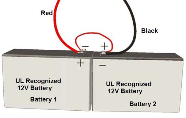
Battery Connection
WARNING
Improper battery connections or shorting battery terminals may damage the system and/or the batteries and
may cause personal injuries.
The control panel battery charge capacity is up to 40AH. Use 12V batteries of the same AH rating. Determine the
correct AH rating as per your current load calculation (see Appendix‐D: Battery Calculations).Wire batteries in
series to produce a 24‐volt equivalent. Do not parallel batteries to increase the AH rating.
Figure 21 Battery Connection
27Installation and Operation Manual
Addressable Loop Circuit Wiring
One ALU card supports one addressable loop circuit.
Addressable Loop Circuit supports Class A and Class B style. A maximum of 252 devices can be connected to the
circuit.
All the compatible detectors and manual stations are polarity insensitive, while the compatible modules are
polarity sensitive.
Refer to the instruction sheets packed with each device.
The detectors and modules may be wired together according to several NFPA defined wiring styles. The wiring
style that is appropriate for your installation should be determined from the relevant building codes and the
local Authority Having Jurisdiction.
Addressable Loop Circuit Wiring – Class A
Class A provides redundant communication paths.
Figure 22 Addressable Loop Circuit Wiring – Class A
28Installation and Operation Manual
Addressable Loop Circuit Wiring – Class B
Class B wiring allows branching of circuit connections.
LA+
LB+
LA‐
LB‐
Figure 23 Addressable Loop Circuit Wiring – Class B
29Installation and Operation Manual
Notification Appliance Circuit Wiring
One NOU card supports two notification appliance circuits.
Refer to the instruction sheets packed with each NAC device.
Notification Appliance Circuit Wiring – Class A
Figure 24 Notification Appliance Circuit Wiring – Class A
30Installation and Operation Manual
Notification Appliance Circuit Wiring – Class B
One EOL (R=10kOhms) is needed at the end of the line to monitor the circuit integrity.
Figure 25 Notification Appliance Circuit Wiring – Class B
31Installation and Operation Manual
Relay Output Circuit Wiring
One ROU card supports five dry contact relays.
Relay contact
(Shown in normal standby condition, see
left drawing)
NO – Normal Open
COM – Common
NC – Normal Close
Figure 26 Relay Output Circuit Wiring
32Installation and Operation Manual
External Network Circuit Wiring
External network circuit can address up to 110 panels and/or remote annunciators.
FW106/FW106C control panel can connect to panels/annunciators by using External Network Unit.
Remote Device Power – The control panel auxiliary power can provide power for 4 annunciators. Each address
on the circuit must be fully powered from either auxiliary power of control panel UL/ULC Listed power supply
for use in fire alarm systems.
When connecting panels/annunciators on the external network circuit, the data wires must be daisy chained
and with no T‐taps to preserve the integrity of the data. The following diagrams show the proper wiring.
External Network Circuit Wiring ‐ Class B
Figure 27 External Network Circuit Wiring ‐ Class B
About the XNU Jumper
Each XNU has an internal jumper on its upper right side which must first be correctly configured.
If this XNU is located at the end of the external network circuit, the jumper
must be switched to “ON”.
33Installation and Operation Manual
If this XNU is located in the middle of the external network circuit, the jumper
must be switched to “OFF”.
Jumper
OFF
AL
AH
BL
BH
XNU
Please refer to the Unit Address Setting section to set the XNU’s address
Auxiliary Power Output Wiring
The Power‐supply and Charging Unit provide auxiliary power output connection. This power output can be
configured as resettable or non‐resettable. The resettable terminal interrupts the power for 6 seconds after a
reset condition.
Figure 28 Auxiliary Power Output Wiring
Communication Port Connection
An Ethernet standard plug is provided for temporary connection to a computer for panel programming.
The Ethernet standard plug is connected to the Ethernet port of the computer that has the FW401 configurator
tool. This is used to upload and/or download panel configuration for programming.
34Installation and Operation Manual
The computer must be disconnected from the panel if not in use.
Figure 29 AMI
35Installation and Operation Manual
System Checkout
The following are the recommended steps that should be followed before and during the powering up of the
FW106/FW106C.
Before Turning the Power ON
1. To prevent sparking, DO NOT connect the battery first. Connecting the batteries should only be done once the
system has been powered from the main AC Supply.
2. Check all field (external) wiring for opens, shorts, and ground.
3. Check that all interconnection cables are secure and that all connectors are plugged in properly.
4. Check all switches for proper setting.
5. Check the AC power wiring for proper connection. Observe/check slide switch position.
6. Close the front cover plate before powering the system from main AC supply.
Power‐up Procedure
1. After completing Before Turning the Power ON procedures, power‐up the panel.
The green AC ON LED should illuminate.
2. Since the batteries are not connected, the Battery Trouble LED should illuminate, the
Trouble LED should flash and the Trouble Relay (on the main board) will be active.
3. Connect the batteries while observing correct polarity; the red wire is positive (+) and black wire is negative
(‐).
4. All indicators should extinguish except for normal power AC ON green LED.
36You can also read