LCO NF C PRE3 Product Manual - LED-Driver - Tridonic
←
→
Page content transcription
If your browser does not render page correctly, please read the page content below
LED-Driver

LCO NF C PRE3
Product Manual
Manual LCO NF C PRE3 | 07-2020 | 1.1 | en

Table of Contents

1. Validity 4
  1.1. Copyright . . . . . . . . . . . . . . . . . . . . . . . . . . . . . . . . . . . . . . . . . . . . . . . . . . . . . . . . . . . . . . . . . . . . . . . . . . . . . . . . . . . . . . . . . . . . . . . . . . . . . . . . . . . . . . . . . 4
  1.2. Imprint . . . . . . . . . . . . . . . . . . . . . . . . . . . . . . . . . . . . . . . . . . . . . . . . . . . . . . . . . . . . . . . . . . . . . . . . . . . . . . . . . . . . . . . . . . . . . . . . . . . . . . . . . . . . . . . . . . . 4

2. General safety instructions 5
  2.1. Intended use . . . . . . . . . . . . . . . . . . . . . . . . . . . . . . . . . . . . . . . . . . . . . . . . . . . . . . . . . . . . . . . . . . . . . . . . . . . . . . . . . . . . . . . . . . . . . . . . . . . . . . . . . . . . . . 5
  2.2. Dangers associated with the operation of the system . . . . . . . . . . . . . . . . . . . . . . . . . . . . . . . . . . . . . . . . . . . . . . . . . . . . . . . . . . . . . . . . . . . . . . . 5
  2.3. Environment . . . . . . . . . . . . . . . . . . . . . . . . . . . . . . . . . . . . . . . . . . . . . . . . . . . . . . . . . . . . . . . . . . . . . . . . . . . . . . . . . . . . . . . . . . . . . . . . . . . . . . . . . . . . . 5
  2.4. Additional instructions . . . . . . . . . . . . . . . . . . . . . . . . . . . . . . . . . . . . . . . . . . . . . . . . . . . . . . . . . . . . . . . . . . . . . . . . . . . . . . . . . . . . . . . . . . . . . . . . . . . . 6

3. Description and key features 7
  3.1. Description of key features . . . . . . . . . . . . . . . . . . . . . . . . . . . . . . . . . . . . . . . . . . . . . . . . . . . . . . . . . . . . . . . . . . . . . . . . . . . . . . . . . . . . . . . . . . . . . . . . 7
  3.2. Main values and functions . . . . . . . . . . . . . . . . . . . . . . . . . . . . . . . . . . . . . . . . . . . . . . . . . . . . . . . . . . . . . . . . . . . . . . . . . . . . . . . . . . . . . . . . . . . . . . . . 8
  3.3. Housing variants . . . . . . . . . . . . . . . . . . . . . . . . . . . . . . . . . . . . . . . . . . . . . . . . . . . . . . . . . . . . . . . . . . . . . . . . . . . . . . . . . . . . . . . . . . . . . . . . . . . . . . . . 10
  3.4. Adjustable output current . . . . . . . . . . . . . . . . . . . . . . . . . . . . . . . . . . . . . . . . . . . . . . . . . . . . . . . . . . . . . . . . . . . . . . . . . . . . . . . . . . . . . . . . . . . . . . . . 11

4. Compatibility between LED module and LED Driver 12
  4.1. Comparison of data sheet values with a 5-point guideline . . . . . . . . . . . . . . . . . . . . . . . . . . . . . . . . . . . . . . . . . . . . . . . . . . . . . . . . . . . . . . . . . . 12
  4.2. Practical tests . . . . . . . . . . . . . . . . . . . . . . . . . . . . . . . . . . . . . . . . . . . . . . . . . . . . . . . . . . . . . . . . . . . . . . . . . . . . . . . . . . . . . . . . . . . . . . . . . . . . . . . . . . . 14
  4.3. Application of the 5-point guideline . . . . . . . . . . . . . . . . . . . . . . . . . . . . . . . . . . . . . . . . . . . . . . . . . . . . . . . . . . . . . . . . . . . . . . . . . . . . . . . . . . . . . . 15

5. Installation notes 21
  5.1. Safety information . . . . . . . . . . . . . . . . . . . . . . . . . . . . . . . . . . . . . . . . . . . . . . . . . . . . . . . . . . . . . . . . . . . . . . . . . . . . . . . . . . . . . . . . . . . . . . . . . . . . . . . 21
  5.2. Function of the earth terminal . . . . . . . . . . . . . . . . . . . . . . . . . . . . . . . . . . . . . . . . . . . . . . . . . . . . . . . . . . . . . . . . . . . . . . . . . . . . . . . . . . . . . . . . . . . . 22
  5.3. Routing the wires . . . . . . . . . . . . . . . . . . . . . . . . . . . . . . . . . . . . . . . . . . . . . . . . . . . . . . . . . . . . . . . . . . . . . . . . . . . . . . . . . . . . . . . . . . . . . . . . . . . . . . . . 24
  5.4. External fuse for DC operation . . . . . . . . . . . . . . . . . . . . . . . . . . . . . . . . . . . . . . . . . . . . . . . . . . . . . . . . . . . . . . . . . . . . . . . . . . . . . . . . . . . . . . . . . . . 25
  5.5. Maximum loading of circuit breakers . . . . . . . . . . . . . . . . . . . . . . . . . . . . . . . . . . . . . . . . . . . . . . . . . . . . . . . . . . . . . . . . . . . . . . . . . . . . . . . . . . . . . 26

6. Functions and interfaces 31
  6.1. IVG Plus . . . . . . . . . . . . . . . . . . . . . . . . . . . . . . . . . . . . . . . . . . . . . . . . . . . . . . . . . . . . . . . . . . . . . . . . . . . . . . . . . . . . . . . . . . . . . . . . . . . . . . . . . . . . . . . . . 31
  6.2. eCLO . . . . . . . . . . . . . . . . . . . . . . . . . . . . . . . . . . . . . . . . . . . . . . . . . . . . . . . . . . . . . . . . . . . . . . . . . . . . . . . . . . . . . . . . . . . . . . . . . . . . . . . . . . . . . . . . . . . 33
  6.3. inputDIM . . . . . . . . . . . . . . . . . . . . . . . . . . . . . . . . . . . . . . . . . . . . . . . . . . . . . . . . . . . . . . . . . . . . . . . . . . . . . . . . . . . . . . . . . . . . . . . . . . . . . . . . . . . . . . . . 35
  6.4. External temperature management . . . . . . . . . . . . . . . . . . . . . . . . . . . . . . . . . . . . . . . . . . . . . . . . . . . . . . . . . . . . . . . . . . . . . . . . . . . . . . . . . . . . . . 37
  6.5. chronoSTEP V3 . . . . . . . . . . . . . . . . . . . . . . . . . . . . . . . . . . . . . . . . . . . . . . . . . . . . . . . . . . . . . . . . . . . . . . . . . . . . . . . . . . . . . . . . . . . . . . . . . . . . . . . . . 39
  6.6. U6Me2 . . . . . . . . . . . . . . . . . . . . . . . . . . . . . . . . . . . . . . . . . . . . . . . . . . . . . . . . . . . . . . . . . . . . . . . . . . . . . . . . . . . . . . . . . . . . . . . . . . . . . . . . . . . . . . . . . . 41
  6.7. DSI . . . . . . . . . . . . . . . . . . . . . . . . . . . . . . . . . . . . . . . . . . . . . . . . . . . . . . . . . . . . . . . . . . . . . . . . . . . . . . . . . . . . . . . . . . . . . . . . . . . . . . . . . . . . . . . . . . . . . 42
  6.8. Power-up Fading . . . . . . . . . . . . . . . . . . . . . . . . . . . . . . . . . . . . . . . . . . . . . . . . . . . . . . . . . . . . . . . . . . . . . . . . . . . . . . . . . . . . . . . . . . . . . . . . . . . . . . . . 43
  6.9. DALI . . . . . . . . . . . . . . . . . . . . . . . . . . . . . . . . . . . . . . . . . . . . . . . . . . . . . . . . . . . . . . . . . . . . . . . . . . . . . . . . . . . . . . . . . . . . . . . . . . . . . . . . . . . . . . . . . . . 44
  6.10. ready2mains . . . . . . . . . . . . . . . . . . . . . . . . . . . . . . . . . . . . . . . . . . . . . . . . . . . . . . . . . . . . . . . . . . . . . . . . . . . . . . . . . . . . . . . . . . . . . . . . . . . . . . . . . . . 46
  6.11. DC recognition . . . . . . . . . . . . . . . . . . . . . . . . . . . . . . . . . . . . . . . . . . . . . . . . . . . . . . . . . . . . . . . . . . . . . . . . . . . . . . . . . . . . . . . . . . . . . . . . . . . . . . . . . 47
  6.12. Dimming on DC . . . . . . . . . . . . . . . . . . . . . . . . . . . . . . . . . . . . . . . . . . . . . . . . . . . . . . . . . . . . . . . . . . . . . . . . . . . . . . . . . . . . . . . . . . . . . . . . . . . . . . . . 48

c                                                                                                                                                                                                                                     2 / 61
Manual LCO NF C PRE3 | 07-2020 | 1.1 | en

Table of Contents

      6.13. Intelligent Temperature Guard . . . . . . . . . . . . . . . . . . . . . . . . . . . . . . . . . . . . . . . . . . . . . . . . . . . . . . . . . . . . . . . . . . . . . . . . . . . . . . . . . . . . . . . . . . 49
      6.14. Surge Burst protection . . . . . . . . . . . . . . . . . . . . . . . . . . . . . . . . . . . . . . . . . . . . . . . . . . . . . . . . . . . . . . . . . . . . . . . . . . . . . . . . . . . . . . . . . . . . . . . . . . 51
      6.15. DiiA Specification . . . . . . . . . . . . . . . . . . . . . . . . . . . . . . . . . . . . . . . . . . . . . . . . . . . . . . . . . . . . . . . . . . . . . . . . . . . . . . . . . . . . . . . . . . . . . . . . . . . . . . . 52
      6.16. Description . . . . . . . . . . . . . . . . . . . . . . . . . . . . . . . . . . . . . . . . . . . . . . . . . . . . . . . . . . . . . . . . . . . . . . . . . . . . . . . . . . . . . . . . . . . . . . . . . . . . . . . . . . . . . 52
      6.17. Commissioning . . . . . . . . . . . . . . . . . . . . . . . . . . . . . . . . . . . . . . . . . . . . . . . . . . . . . . . . . . . . . . . . . . . . . . . . . . . . . . . . . . . . . . . . . . . . . . . . . . . . . . . . . 52
      6.18. NFC . . . . . . . . . . . . . . . . . . . . . . . . . . . . . . . . . . . . . . . . . . . . . . . . . . . . . . . . . . . . . . . . . . . . . . . . . . . . . . . . . . . . . . . . . . . . . . . . . . . . . . . . . . . . . . . . . . . 54
      6.19. sensorMODE . . . . . . . . . . . . . . . . . . . . . . . . . . . . . . . . . . . . . . . . . . . . . . . . . . . . . . . . . . . . . . . . . . . . . . . . . . . . . . . . . . . . . . . . . . . . . . . . . . . . . . . . . . . 55

7. Reference list 60
      7.1. Additional information . . . . . . . . . . . . . . . . . . . . . . . . . . . . . . . . . . . . . . . . . . . . . . . . . . . . . . . . . . . . . . . . . . . . . . . . . . . . . . . . . . . . . . . . . . . . . . . . . . . 60
      7.2. Downloads . . . . . . . . . . . . . . . . . . . . . . . . . . . . . . . . . . . . . . . . . . . . . . . . . . . . . . . . . . . . . . . . . . . . . . . . . . . . . . . . . . . . . . . . . . . . . . . . . . . . . . . . . . . . . . 60
      7.3. Technical data . . . . . . . . . . . . . . . . . . . . . . . . . . . . . . . . . . . . . . . . . . . . . . . . . . . . . . . . . . . . . . . . . . . . . . . . . . . . . . . . . . . . . . . . . . . . . . . . . . . . . . . . . . . 61

...

c                                                                                                                                                                                                                                      3 / 61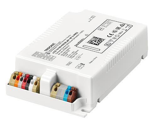
Manual LCO NF C PRE3 | 07-2020 | 1.1 | en

Scope of documentation

These operating instructions are valid for LED Drivers of the LCO NF C PRE3 series.

TRIDONIC GmbH & Co KG is constantly striving to develop all its products. This means that there may be changes in form, equipment
and technology.
Claims cannot therefore be made on the basis of information, diagrams or descriptions in these instructions.
The latest version of these operating instructions is available on our home page.

Copyright
This documentation may not be changed, expanded, copied or passed to third parties without the prior written agreement of
TRIDONIC GmbH & Co KG.
We are always open to comments, corrections and requests. Please send them to info@tridonic.com

Imprint
Tridonic GmbH & Co KG
Färbergasse 15
6851 Dornbirn
Austria

T +43 5572 395-0
F +43 5572 20176

www.tridonic.com

...

c                                                                                                                           4 / 61
Manual LCO NF C PRE3 | 07-2020 | 1.1 | en

General safety instructions

The instructions in this section have been compiled to ensure that operators and users of LED Drivers of the LCO NF C PRE3 series
from Tridonic are able to detect potential risks on time and take the necessary preventative measures.
The operator must ensure that all users fully understand these instructions and follow them. This device may only be installed and
configured by suitably qualified personnel.

Intended use
Proper use
Operation of LED light modules. The device may only be used for this intended purpose.

Improper use
Outdoor use. Extensions and modifications to the product.

 ½ WARNING!
 Improper use could result in injury, malfunction or damage to property.
 It must be ensured that the operator informs every user of existing hazards.

Dangers associated with the operation of the system
 ½ DANGER!
 Danger of electrocution
 Disconnect the power of the entire lighting system before working on the lighting system!

Environment
 ½ DANGER!
 Not to be used in corrosive or explosive environments.

 ½ CAUTION!
 Risk of damage caused by humidity and condensation

  _ Use use the control device only in dry rooms and protect it against humidity!
  _ Prior to commissioning the system, wait until the control device is at room temperature and completely dry!

c                                                                                                                           5 / 61
Manual LCO NF C PRE3 | 07-2020 | 1.1 | en

General safety instructions

Additional instructions
 ½ CAUTION!
      Electromagnetic compatibility (EMC)
      Although the device meets the stringent requirements of the appropriate directives and standards on electromagnetic
      compatibility, it could potentially interfere with other devices under certain circumstances!

...

c                                                                                                                           6 / 61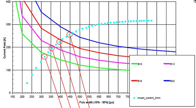
Manual LCO NF C PRE3 | 07-2020 | 1.1 | en

Description and key features

Description of key features
LCO NF C PRE3 is a specially designed portfolio for outdoor and industrial applications. It has been optimised to meet the hardest
requirements in outdoor LED applications.

      _ Special design:
        The LCO NF C PRE3 offer a safe and reliable solution under difficult weather and electrical circumstances (e.g. street and
        roadlight, tunnel, carpark)
      _ Lifetime:
        Excellent lifetime thanks to special design
      _ Safety:
        Up to 10 kV surge/burst protection
      _ Thermomanagement:
        ta up to 70 °C with 65,000 hours lifetime
      _ State-of-the-art dimming technology:
        Stepless dimming from 100 to 1 %
      _ Diversity of functions:
         _ NFC, U6Me2, ready2mains, DALI, ETM, AUX 24V, D4i

...

c                                                                                                                                    7 / 61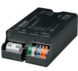
Manual LCO NF C PRE3 | 07-2020 | 1.1 | en

Main values and functions

Main values and functions
Dimming
 Portfolio                                  Description

 Dimmable

 Dimming method                             Amplitude dimming

 Dimming range                              100 to 1 %

 Dimming curve                              Logarithmic dimming curve (standard)
                                            Switching to linear dimming curve is possible.

 Dimming interfaces                         DALI V2-DT6, DSI, ready2mains, chronoSTEP V3

Functions
 Portfolio                                                    Description

 Intelligent Voltage Guard

 Intelligent Temperature Guard

 Power-up Fading

 DC Operation                                                 DC level adjustable
                                                              supporting EN 50172

 Configuration Interfaces                                     NFC, DALI V2-DT6, ready2mains, U6Me2

  eCLO

Output current
 Portfolio                         Description

 Adjustable output current

 Adjustable via...                 NFC, DALI V2-DT6, ready2mains

 Step size                         1 mA

 Tolerance                         Further information can be found in the data sheet (see Reference list, p. 60).

c                                                                                                                    8 / 61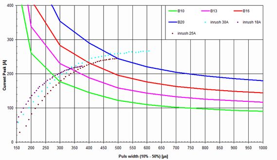
Manual LCO NF C PRE3 | 07-2020 | 1.1 | en

Main values and functions

Technical data
      Portfolio                             Description

      Rated supply voltage                  220-240 V

      Standby losses                        < 0.3 W

...

c                                                         9 / 61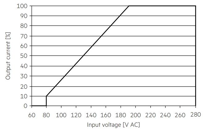
Manual LCO NF C PRE3 | 07-2020 | 1.1 | en
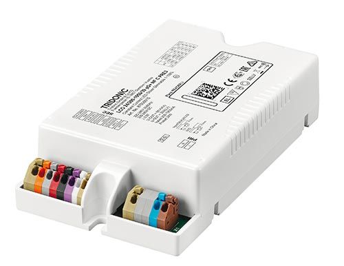
Housing variants
Housing variants
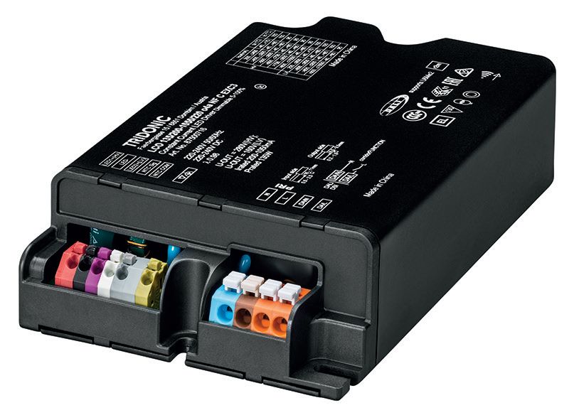
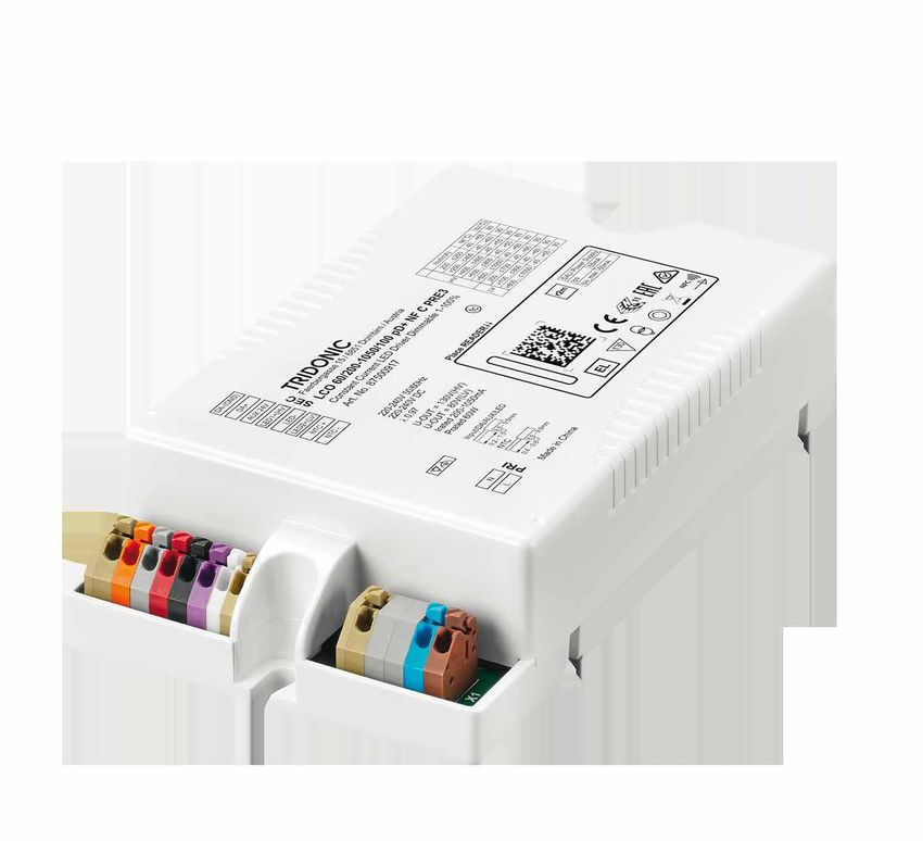
LCO NF C PRE3 is available in the following housing variants:
Image Description
Housing variant compact
_ Compact shape for installation inside the luminaire casing
(in-built)
Typical area of application: Road, street, industry
Housing variant compact potted
_ Compact shape for installation inside the luminaire casing
(in-built)
_ Typical area of application: Road, street, industry
...
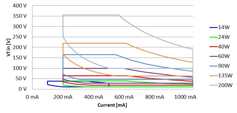
c 10 / 61Manual LCO NF C PRE3 | 07-2020 | 1.1 | en Adjustable output current Adjustable output current The output current can be adjusted via NFC, DALI V2-DT6, ready2mains Adjusting the output current via DALI or ready2mains Further information about DALI (see DALI, p. 44) or ready2mains (see ready2mains, p. 46) can be found in the corresponding function description of the DALI manual (see Reference list, p. 60). Adjusting the output current via NFC The NFC Interface allows wireless communication with the LED Driver. This interface offers the option to write configuration and to read configuration, errors and events with the companionSUITE. A correct communication between the LED Driver and the NFC antenna can only be guaranteed if the Driver is directly placed on the antenna. Any material placed between the LED Driver and the NFC antenna can cause a deterioration of the communication quality. We recommend the use of following NFC antennas: www.tridonic.com/nfc-readers NFC is compliant with ISO/IEC 15963 standard. Output voltage The output voltage range results from the selected current. More information can be found in the data sheet (see Reference list, p. 60). The output current can be adjusted via NFC, DALI or ready2mains. The diagrams below show the forward voltage ranges as a function of the output current and are intended as a guide. For detailed values and an explanation of the methods available please refer to the data sheets (see Reference list, p. 60). ... c 11 / 61
Manual LCO NF C PRE3 | 07-2020 | 1.1 | en

Compatibility between LED module and LED Driver

There are two stages involved in the check for compatibility between the LED module and the LED Driver.

      _ The requirements for operating together can be checked by comparing the data sheets
      _ Subsequent practical tests can ensure that there are no unexpected problems during actual operation

Comparison of data sheet values with a 5-point guideline
Different values for the two devices need to be considered when comparing the data sheets. The following table shows which values
are involved and which requirements they must meet.

      Comparison    Value in LED          Value in LED
      of…                module           Driver             Detailed procedure

      (1) Current       Irated @HO   >=   Output current     _ Determine forward current of module
                                                             _ Check whether LED Driver can be operated with the same output
                              Imax   >=   Output current +
                                                               current
                                          tolerances
                                                             _ Check whether Imax of module is greater than or equal to output
                                                               current of LED Driver (including tolerances)

                                                             ½ CAUTION!
                                                              The Imax can be temperature dependent!
                                                              Refer to the derating curve of the LED module data sheet.

                                                                                                                          turn page... ->

...

c                                                                                                                                12 / 61
Manual LCO NF C PRE3 | 07-2020 | 1.1 | en
Compatibility between LED module and LED Driver
Comparison Value in LED Value in LED
of… module Driver Detailed procedure
(2) Voltage Min. forward > Min. output _ Check whether voltage range of LED module is completely within the
voltage voltage voltage range of LED Driver
Max. forward < Max. output
voltage voltage ½ CAUTION!
The forward voltage is temperature dependent!
Refer to the Vf/tp diagram in the data sheet.
Min. forward > Min. output Only relevant for dimmable LED Driver !
voltage voltage
@ min. dim
level I NOTICE
To ensure full dimming performance the forward voltage of the LED
module at min. dim level must be greater than or equal to the min.
output voltage of the driver.
_ Determine the forward voltage of the LED module at lowest dim level
_ In case there is no data available for the LED module at lowest dim
level: take the min. forward voltage minus 20% as an approximation
_ Check whether the forward voltage of the LED module is greater
than or equal to the min. output voltage of the driver
(3) LF current Max. >= Output LF _ Check whether max. permissible LF current ripple of LED module is
ripple permissible current ripple greater than or equal to output LF current ripple of LED Driver
LF current ( Max. output _ Check whether max. permissible peak current of LED module is
current permissible current peak greater than max. output current peak of LED Driver
peak current
(5) Power Min. power > Min. output _ Check whether power range of LED module is completely within
(pertinent for consumption power output power range of LED Driver
multi channel
Max. power < Max. output
LED Driver)
consumption power
c 13 / 61Manual LCO NF C PRE3 | 07-2020 | 1.1 | en Compatibility between LED module and LED Driver Practical tests ½ CAUTION! Following the comparison of the data sheet values a practical test is required. Only a practical test can ensure that the system components (luminaire, LED Driver , LED module, wiring) are coordinated and working properly. The following aspects must be checked: Technical aspects _ Transient behaviour _ Colour shift _ Connection during operation _ Parasitic capacitance Visual aspects _ Flickering _ Stroboscopic effect (video applications) _ Dimming behaviour _ Colour change/stability _ Luminous flux When conducting the tests the following conditions must be considered: Conditions _ All tolerances _ Entire temperature range _ Different output voltage ranges (incl. no load) _ Entire dimming range _ Short circuit I NOTE If the values are slightly over or under the specified threshold values or if there are any other concerns or questions please contact your 1st level technical support. c 14 / 61
Manual LCO NF C PRE3 | 07-2020 | 1.1 | en

Compatibility between LED module and LED Driver

Application of the 5-point guideline
The compatibility check with the 5-point guideline is shown here using two examples.

Example 1
Comparison data for LED Driver

  LED Driver

  Designation                 LCA 75W 250–750mA one4all C PRE OTD

  Manufacturer                TRIDONIC

  Data sheet values of LED Driver

  Output current                                                                       700 mA

  Output current tolerance                                                             ±3%

  Min. output voltage                                                                  45 V (1)

  Max. output voltage                                                                  107 V (1)

  Output LF current ripple                                                             ±5%

  Max. output current peak                                                             980 mA

  Output power                                                                         75.0 W

(1)   Values at 700 mA

c                                                                                                  15 / 61
Manual LCO NF C PRE3 | 07-2020 | 1.1 | en

Compatibility between LED module and LED Driver

Comparison data for LED module

      LED module

      Designation       RLE G1 49x223mm 4000lm 830 PL1 EXC OTD

      Manufacturer      Tridonic

      Data sheet values of LED module

      Forward current                               700 mA

      Max. DC forward current                       1400 mA

      Typ. forward voltage                          33 V +/-10 % (1)

      Min. forward voltage                          43.6 V (1)

      Max. forward voltage                          49.8 V (1)

      Max. permissible LF current ripple            1800 mA

      Max. permissible peak current                 2,000 mA

      Power draw                                    32.14 W

(1)    Values at 700 mA

Questions
      _ Is the LED Driver able to operate two modules?
      _ Can the required luminous flux of 3,000 lm be achieved with this combination?

...

c                                                                                       16 / 61
Manual LCO NF C PRE3 | 07-2020 | 1.1 | en
Compatibility between LED module and LED Driver
Procedure
Comparison of data sheet values
Comparison Value Value in
of… in LED module LED Driver Result Explanation
(1) Current 700 mA = 700 mA _ To produce a luminous flux of 3,000 lm, the two LED modules
must be operated with a forward current of 700 mA.
_ The LED Driver can be set so that it delivers precisely this value
of 700 mA as the output current.
1400 mA >= 721 mA _ The output current of the LED Driver including tolerances (700
mA + 3 % = 721 mA) is less than or equal to the max. DC forward
current of the LED module (1400 mA).
(2) Voltage 87.2 V > 45 V _ The voltage range of the LED module (2 x 43.6 V = 87.2 V; 2 x
49.8 V = 99.6 V) lies completely within the voltage range of the
99.6 V < 107 V LED Driver (45 - 107 V).
(3) LF 1800 mA > 735 mA _ The Output LF current ripple (5 % of output current plus
current tolerances: [700 mA + 5 %] x 1.05 = 735 mA) of the LED Driver
ripple is less than the max. permissible LF current ripple of the LED
module (1800 mA).
(4) Max. 2000 mA > 980 mA _ The max. output current peak of the LED Driver (700 mA + 20 %
peak current = 980 mA) is less than the max. permissible peak current with
which the LED module can be operated (2,000 mA).
(5) Power 64.8 W < 75.0 W _ The power draw of the LED module (64.8 W) is less than the
output power of the LED Driver (75.0 W).
Result
All the values meet the requirements. The components are mutually compatible.
With 2 modules a luminous flux of 3,713 lm will be achieved.
c 17 / 61Manual LCO NF C PRE3 | 07-2020 | 1.1 | en Compatibility between LED module and LED Driver Example 2 Comparison data for LED Driver LED Driver Designation LCA 75W 250–750mA one4all C PRE OTD Manufacturer TRIDONIC Data sheet values of LED Driver Output current 700 mA Output current tolerance ±3% Min. output voltage 45 V (1) Max. output voltage 107 V (1) Output LF current ripple ±5% Max. output current peak 980 mA Output power 75.0 W (1) Values at 700 mA c 18 / 61
Manual LCO NF C PRE3 | 07-2020 | 1.1 | en

Compatibility between LED module and LED Driver

Comparison data for LED module

      LED module

      Designation                          Fictitious LED module

      Manufacturer                         Other manufacturer

      Data sheet values of LED module

      Forward current                                              700 mA

      Max. DC forward current                                      1,050 mA

      Typ. forward voltage                                         39.5 V +/-10 % (1)

      Min. forward voltage                                         35.55 V (1)

      Max. forward voltage                                         43.45 V (1)

      Max. permissible LF current ripple                           630 mA

      Max. permissible peak current                                1,500 mA

      Power draw                                                   19.75 W

(1)    Values at 700 mA

Questions
      _ Are the two components mutually compatible?
      _ Can the required luminous flux of 1,800 lm be achieved with this combination?

...

c                                                                                       19 / 61
Manual LCO NF C PRE3 | 07-2020 | 1.1 | en
Compatibility between LED module and LED Driver
Procedure
Comparison of data sheet values
Comparison Value Value in
of… in LED module LED Driver Result Explanation
(1) Current 700 mA = 700 mA _ To produce a luminous flux of 1,800 lm the LED module must be
operated with a forward current of 700 mA.
_ The LED Driver can be set so that it delivers precisely this value
of 700 mA as the output current.
1,050 mA >= 721 mA _ The output current of the LED Driver including tolerances (700
mA + 5 % = 721 mA) is less than or equal to the max. DC forward
current of the LED module (1,050 mA).
(2) Voltage 35.55 V > 45 V _ The voltage range of the LED module (35.55 V - 43.45 V) is not
within the voltage range of the LED Driver (45 V - 107 V)
43.45 V < 107 V
(3) LF 630 mA > 735 mA _ The Output LF current ripple (2 % of output current plus
current tolerances: [700 mA + 5 %] x 1.02 = 735 mA) of the LED Driver
ripple is not less than the max. permissible LF current ripple of the
LED module (630 mA).
(4) Max. 1,500 mA > 980 mA _ The max. output current peak of the LED Driver (700 mA + 20 %
peak current = 980 mA) is less than the max. permissible peak current with
which the LED module can be operated (1,500 mA).
(5) Power 19.75 W < 75 W _ The power draw of the LED module (19.75 W) is less than the
output power of the LED Driver (75.0 W).
Result
One of the values does not meet the requirements. The components are not mutually compatible.
...
c 20 / 61Manual LCO NF C PRE3 | 07-2020 | 1.1 | en
Installation notes
I NOTICE
The cabling, wiring and mounting for a LED Driver varies depending on the design and manufacturer of the LED module.
The following description should therefore not be viewed as comprehensive installation instructions but merely as important
general information.
To obtain further information, proceed as follows:
_ Read the documentation provided by the lamp manufacturer. Follow the guidelines and instructions of the lamp
manufacturer!
_ Observe all relevant standards. Follow the instructions given in the standards!
Safety information
½ WARNING!
_ Comply with the general safety instructions (see General safety instructions, p. 5) !
_ To avoid failures due to ground faults protect the wiring against mechanical loads from sharp-edged metal parts (e.g. cable
penetrations, cable holders, metal frames, etc.
_ LED Drivers from Tridonic are protected for a maximum of 48 hour against overvoltage of up to 320 V. Make sure that the
LED Driver is not exposed to overvoltages for long periods!
_ LED Drivers of the LCO NF C PRE3 series from Tridonic have type of protection IP 20. Comply with the requirements for this
type of protection!
...
c 21 / 61Manual LCO NF C PRE3 | 07-2020 | 1.1 | en Installation notes Function of the earth terminal The earth connection is conducted as protection earth (PE). The LED Driver can be earthed via earth terminal or metal housing (if device has metal housing). If the LED Driver will be earthed, protection earth (PE) has to be used. There is no earth connection required for the functionality of the LED Driver. Earth connection is recommended to improve following behaviour. _ Electromagnetic interferences (EMI) _ LED glowing at standby _ Transmission of mains transients to the LED output In general, it is recommended to earth the LED Driver if the LED module is mounted on earthed luminaire parts respectively heat sinks and thereby representing a high capacity against earth. Avoiding residual LED glow on standby Residual LED glow on standby may occur as a result of capacitive leakage currents from the LED module onto earthed luminaire parts (such as the heat sink). This mainly affects high-efficiency LED systems with large surface areas installed in luminaires with protection class 1. The topology has been improved so that residual LED glow can be virtually eliminated by earthing the devices. I NOTICE If the LED Driver cannot be earthed or if earthing is not desired, residual LED glow can be minimised by adequate insulation (for example by using heat-conducting double-sided insulation foil). Avoiding the transfer of mains transients to the LED output The transfer of mains transients to the LED output presents a problem for many LED Driver topologies currently on the market, and TRIDONIC devices may be affected. Voltage peaks at the input of the LED Driver may be transferred to the output of the device where they lead to differences in potential between the LED output and earthed luminaire parts. These differences in potential may result in flashovers if the insulation is inadequate or if the creepage and clearance distances are too small. Flashovers will cause the LED module to fail. Earthing the LED Driver attenuates voltage peaks and reduces the likelihood of flashovers. The precise degree of attenuation depends on the capacitance of the LED module with respect to earth. If voltages at the output are higher than 0.5 kV, it is mentioned in the data sheet. c 22 / 61
Manual LCO NF C PRE3 | 07-2020 | 1.1 | en

Installation notes

Figure: Voltage peaks for LED driver without earthing (left) and with earthing (right)

 I NOTICE
      Irrespective of whether the LED Driver is earthed or not, LED modules must be insulated in accordance with the requirements of
      the luminaire protection class. Improved insulation of the LED module can also reduce the likelihood of flashovers.

...

c                                                                                                                             23 / 61
Manual LCO NF C PRE3 | 07-2020 | 1.1 | en Installation notes Routing the wires Tests I NOTICE The performance of the prescribed tests and compliance with relevant standards are the responsibility of the luminaire manufacturer. The following descriptions merely indicate the most important tests and are no substitute for a full research of the relevant standards. Insulation and dielectric strength testing of luminaires LED Driver for lamps are sensitive to high-voltage transients. This must be taken into consideration when subjecting luminaires to routine testing during manufacture. According to IEC 60598-1 Annex Q (for information only!) and ENEC 303-Annex A, each luminaire should be subjected to an insulation test for 1 second at 500 V DC. The test voltage is applied between the linked phase/neutral conductor terminal and the protective earth terminal. The insulation resistance must be at least 2 megaohm. As an alternative to measuring the insulation resistance, IEC 60598-1 Annex Q describes a dielectric strength test at 1500 V AC (or 1.414 x 1,500 V DC). To avoid damaging LED Driver, this dielectric strength test should be performed exclusively for type testing. This test should certainly not be used for routine testing. I NOTICE Tridonic recommends performing an insulation test because a dielectric strength test may damage the device irreparably. Type testing Type testing of the luminaire is performed according to IEC 60598-1 Section 10. The wiring for protection class 1 luminaires is tested at a voltage of 2xU + 1,000 V. In order not to overload the LED Driver all the inputs and outputs of the LED Driver are connected to one another. Uout is used for measuring the voltage for luminaires with LED Driver with U out > 250 V: For Uout 480 V the voltage for the type test is 2000 V. (Routine testing is always performed at 500 V DC) Wiring I NOTICE The wiring procedure is device specific. Further information about wiring, wire cross sections and the length of stripped off insulation can be found in the data sheet. c 24 / 61
Manual LCO NF C PRE3 | 07-2020 | 1.1 | en

Installation notes

Wiring guidelines
 _ The cables should be run separately from the mains connections and mains cables to ensure good EMC conditions.
 _ The LED wiring should be kept as short as possible to ensure good EMC. The max. secondary cable length is 2 m (4 m circuit),
   this applies for LED output as well as for temperature sensor.
 _ Depending on the design of the luminaire it may be possible to improve the radio interference properties by earthing the
   device at the earth connection.
 _ The LED Driver has no inverse-polarity protection on the secondary side. Wrong polarity can damage LED modules with no
   inverse-polarity protection.

Wiring the plug-in terminal

 _ Use solid wire or stranded wire with the correct cross-section
 _ Strip off correct length of insulation; you may need to twist the tool slightly
 _ If stranded wire is used: push onto the terminal from above to be able to insert the wire
 _ Insert the bare end into the terminal

Detaching the plug-in terminal

 _ Push onto the terminal from above to release the wire
 _ Pull out the wire at the front

External fuse for DC operation
The internal fuse of an LED Driver is not rated for DC operation. Because of this, an additional external fuse must be used if an LED
Driver is operated on a DC network.

Proceed as follows:

 _ Connect the external fuse to the line labeled "+" which is between the DC power supply and the input terminal of the LED
   Driver
 _ Only use an external fuse with suitable parameters.

For LED Drivers with a power of 25-150 watts the following values are recommended:

 _ Rated voltage: 250 V
 _ DC rated power: 1 A - 3 A Time-Lag (SLO-Blo®)

Tridonic recommends the following external fuse:

 _ 477 Series, 5 × 20 mm, Time-Lag (Slo-Blo®) Fuse Rating 3.15 A

c                                                                                                                             25 / 61
Manual LCO NF C PRE3 | 07-2020 | 1.1 | en

Installation notes

Maximum loading of circuit breakers
Importance of maximum loading
A circuit breaker is an automatically operated electrical switch that protects an electrical circuit from damage caused by overload or
short circuit. Unlike a fuse that must be replaced if it triggers, a circuit breaker can be reset (either manually or automatically) and
used further. Circuit breakers are available in different sizes and with different technical data.

The inrush current is a short increased peak current that occurs when an electronic control gear is switched on.

In electrical installations, numerous control gear are connected to one circuit breaker. The maximum loading of a circuit breaker
indicates how many control gear can be connected to the circuit breaker without triggering the circuit breaker because of the
summation of the different inrush currents. The value is calculated through simulation programs based on the circuit breakers
characteristic.

Information about the maximum loading can be found in Tridonic data sheets. The following table shows the data for LCO
60/200-1050/100 o4a NF C EXC3 as an example.

 Automatic circuit breaker type                      C10     C13     C16     C20         B10   B13   B16     B20       Inrush current

 Installation Ø (in mm2)                              1,5     1,5    2,5      4          1,5   1,5   2,5      4        Imax        time

  LCO 60/200-1050/100 o4a NF C EXC3                   16      21     26       33         10    13     16      20      28.4 A      270 µs

Calculation of maximum loading
Tripping characteristics of circuit breakers
The load at which a circuit breaker triggers is defined by the height and the duration of the applied current.
The following table shows exemplary values for different circuit breakers (B10, B13, B16, B20).

 Duration                  Current B10               Current B13                   Current B16                Current B20
 [µs]                      [Apeak]                   [Apeak]                       [Apeak]                    [Apeak]

 100                       700                       910                           1,120                      1,400

 200                       260                       338                           416                        520

 300                       177                       230.1                         283                        354

 400                       145                       188.5                         232                        290

 500                       122                       158.6                         195                        244

 600                       110                       143                           176                        220

 700                       102                       132.6                         163                        204

c                                                                                                                               26 / 61
Manual LCO NF C PRE3 | 07-2020 | 1.1 | en
Installation notes
800 97 126.1 155 194
900 93 120.9 149 186
1000 90 117 144 180
The combination of both parameters can also be displayed graphically. This results in the tripping characteristic for a certain circuit
breaker.
Current [A]
Duration [µs]
I NOTICE
Information about the specific tripping characteristics of a circuit breaker must be requested from the respective manufacturer !
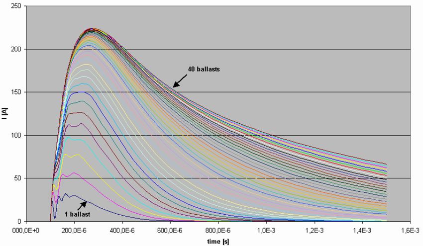
Calculation of the inrush current
The inrush current of a control gear is also defined by its duration and its height. The duration is typically measured as the time
between 10 % of maximum current (ascending) and 50 % of maximum current (descending).
The following illustration shows the inrush current of a single control gear:
c 27 / 61Manual LCO NF C PRE3 | 07-2020 | 1.1 | en Installation notes If several control gear are connected to one circuit breaker, the individual inrush currents add up. Implementation of the simulation The above-mentioned parameters, height and duration of the current pulse in both the circuit breaker and the control gear, are entered into the simulation program. The result of the simulation is presented in graphical form. The different elements have the following meaning: _ Circuit breaker: B10, B13, B16, B20 (solid line) represent the tripping characteristics of different circuit breakers. c 28 / 61
Manual LCO NF C PRE3 | 07-2020 | 1.1 | en

Installation notes

 _ Inrush current:
   The dotted lines represent different inrush currents.
   The index of a point signifies the number of control gear, that is, point 1 represents the result for 1 control gear, point 2 the
   result for 2 control gear, etc.

The simulation results can be read as follows:

 _ The crossing of the two lines shows the maximum value for the selected combination of circuit breaker and inrush current.
 _ The index of the point at this maximum value shows the max. number of control gear.

The following example shows the maximum number of control gear at four different circuit breakers:

 _ max. 5 devices at circuit breaker B10 (green tripping characteristic)
 _ max. 7 devices at circuit breaker B13 (pink tripping characteristic)
 _ max. 9 devices at circuit breaker B16 (red tripping characteristic)
 _ max. 12 devices at circuit breaker B20 (blue tripping characteristic)

c                                                                                                                                29 / 61
Manual LCO NF C PRE3 | 07-2020 | 1.1 | en

Installation notes

 I NOTICE
      The results of different simulations can only be compared if all of the relevant factors are the same. The following points can
      influence the results:

      _ Tripping characteristic used for the circuit breakers
      _ Definition used for the duration of the inrush current (Tridonic: 10-50 %)
      _ Gear used for the measurement of the inrush current (especially important: Which electrolytic capacitor is installed in the
        control gear?)
      _ Considering a safety buffer (Tridonic: +20 % for the electrolytic capacitor )
      _ Considering different system impedance
      _ Switch-on point used: should always be at max. input voltage
      _ Adopted cable lengths and cable data (Tridonic: Cable length 40 cm; Resistivity: 0.0172 ohm * mm 2 / m; inductance: 5 nH /
        cm; terminal resistance: 2 milliohm)
      _ The modeling of the control gear is performed from the input to the bus voltage electrolytic capacitor . For inductance the
        saturation values must be used.

...

c                                                                                                                                  30 / 61
Manual LCO NF C PRE3 | 07-2020 | 1.1 | en Functions and interfaces IVG Plus Description In some cases mains voltage is not stabilized and has some voltage peaks which are lower or higher than the nominal voltage range. Between 192 V and 80 V input voltage, the LED Driver operates in undervoltage mode and dims the secondary side linearly down to 10 %. Below 80 V input voltage, the LED Driver shuts down, restarts at 90 V (without a reset) and dims linearly up back to 100 %. Above 280 V input voltage, the LED Driver shuts down. If input voltage drops below 270 V, the LED Driver restarts (without a reset). ½ WARNING! If the driver is operated on voltages higher >280V it will turn off automatically. This is a safety feature only on streetlight a pplications. I NOTICE Input Voltage Guard Plus (IVG+) has a higher priority than inputDIM. I NOTICE If overvoltage is detected, the connected sensors are ignored. c 31 / 61
Manual LCO NF C PRE3 | 07-2020 | 1.1 | en

IVG Plus

Commissioning
Activating the IVG Plus function
The IVG Plus function is activated by default.

Deactivating the IVG Plus function
Deactivating the IVG Plus function via masterCONFIGURATOR
The eCLO function can be deactivated via the masterCONFIGURATOR.
Further information can be found in the masterCONFIGURATOR manual (see
http://www.tridonic.com/com/en/download/Manual_masterConfigurator_en.pdf).

...

c                                                                            32 / 61
Manual LCO NF C PRE3 | 07-2020 | 1.1 | en

eCLO

eCLO
Description
The light output of an LED module reduces over the course of its lifetime.
The eCLO function (enhanced Constant Light Output) compensates for this natural decline by constantly increasing the output
current of the LED Driver throughout its lifetime.

As a results, a virtually uniform light output is achieved at all times.

Up to 8 steps, each with a timer value and an intensity value, can be used for the configuration.

Starting from these steps, the control of the output current takes place automatically. If the function "visual feedback" is enabled,
visual feedback is given as soon as the LED exceeds the expected LED lifetime, see table "Parameter".

c                                                                                                                               33 / 61
Manual LCO NF C PRE3 | 07-2020 | 1.1 | en

eCLO

Parameter
                      Default                                                                                               Min        Max
      Parameter        value    Description                                                                                value      value

      Initial timer     0h      The initial timer value is always 0.                                                        0h          0h
      value                     The function will be started from this step.

      Initial         100 %     Specifies the intensity, with which the function is started.                               70 %       100 %
      intensity

      Step 1 - 7        0h      For each of the 7 further steps (1 - 7) a separate timer value can be specified.            0h     127,500 h
      timer value               After the period specified here, the respective intensity of the level (1 - 7) is taken.
                                The 7 timer values are to be entered as absolute values.

      Step 1 - 7      100 %     For each of the 7 further steps (1 - 7) an intensity can be specified.                     70 %       100 %
      intensity                 If one of the levels is defined as 100 %, the function is ended at this step.

      LED burning       0h      Makes it possible to adjust the burning hours of an LED.                                    0h     131,070 h
      hours                     With this, LEDs with different burning hours can be matched to each other when
                                LEDs are replaced.

      Visual            Off     If visual feedback is enabled, visual feedback is given as soon as the LED exceeds          Off          On
      feedback                  the expected LED lamp life.
                                If the expected LED lamp life is exceeded, the luminaire flashes for 2 seconds after
                                being switched on.

Commissioning
Activating and adjusting the eCLO function
Activating and adjusting the eCLO function via companionSUITE (valid for EXC3 and ADV3)
The eCLO function can be activated and adjusted via companionSUITE.
Further information can be found on the Tridonic homepage at http://www.tridonic.com/download/help/Overview_en.html and
http://www.tridonic.com/download/help/Enhanced_constant_light_output_eCLO_en.html.

Activating and adjusting the eCLO function via masterCONFIGURATOR (valid only for EXC3)
The eCLO function can be activated and adjusted via the masterCONFIGURATOR.
Further information can be found in the masterCONFIGURATOR manual (see
http://www.tridonic.com/com/en/download/Manual_masterConfigurator_en.pdf).

...

c                                                                                                                                  34 / 61
Manual LCO NF C PRE3 | 07-2020 | 1.1 | en inputDIM inputDIM Description inputDIM enables dimming with the variation of mains voltage between 170 and 250 V AC. The max. / min. dimming level can be set via appropriate software. The associated voltage for the max. / min. dimming level can be set individually within the voltage range stated above. The input voltage regulation IVG Plus has higher priority than inputDIM. If the min. dimming level set by the inputDIM function is higher than the max. allowed dimming level of IVG Plus, the value of IVG Plus has priority. Depending on the level of the input voltage, the intensity of the LED can be set with two adjustable interpolation points. Between the two interpolation points the values are interpolated linearly. c 35 / 61
Manual LCO NF C PRE3 | 07-2020 | 1.1 | en

inputDIM

Parameter
                  Default
      Parameter    value    Description                                                          Min value         Max value

      Minimum      30 %     Interpolation point 1: Defines the minimum level of the LED.           10 %                    85 %
      level

      Minimum     180 V     Interpolation point 1: Defines the input voltage up to which the       170 V             Maximum
      voltage               minimum level of the LED is set.                                                    voltage - 20 V

      Maximum     100 %     Interpolation point 2: Defines the maximum level of the LED.           30 %                   100 %
      level

      Maximum     220 V     Interpolation point 2: Defines the voltage from which on the           196 V                  250 V
      voltage               maximum level of the LED is set.                                    =< Maximum
                                                                                               voltage + 20 V

Commissioning
Activating and adjusting the inputDIM function
Activating and adjusting the inputDIM function via companionSUITE
The inputDIM function can be activated and adjusted via companionSUITE.
Further information can be found on the Tridonic homepage at http://www.tridonic.com/download/help/Overview_en.html and
http://www.tridonic.com/download/help/inputDIM_en.html.

Activating and adjusting the inputDIM function via masterCONFIGURATOR
The inputDIM function can be activated and adjusted via the masterCONFIGURATOR.
Further information can be found in the masterCONFIGURATOR manual (see
http://www.tridonic.com/com/en/download/Manual_masterConfigurator_en.pdf).

Activating and adjusting the inputDIM function via ready2mains
The inputDIM function can be activated and adjusted via ready2mains.
Further information can be found in the Product manual ready2mains Programmer (see
http://www.tridonic.com/com/en/download/technical/ready2mains_Programmer_ProductManual_en.pdf).

...

c                                                                                                                   36 / 61
Manual LCO NF C PRE3 | 07-2020 | 1.1 | en ETM External temperature management Description ETM protects the LED module against thermal overstress. An external temperature sensor (NTC) detects the LED module temperature and the LED Driver will limit the output current according to this temperature: If the temperature is between the limits T1 (normal condition) and T2 (overload), the LED output current will be decreased. If the temperature exceeds the limit T3 (critical temperature), the device will switch to the shutdown level. The shutdown level will be active until the module temperature decreases below T1 or until the LED Driver is restarted (switch off or mains reset). I NOTICE The LED module’s temperature is only measured if the output is active (lamp is on). The allowed NTC resistor value is between 0 to 2 megaohm. By default there are three predefined values that can be set via programming software, up to five individual values can be added. The temperature sensor (NTC) is defined by two parameters, the resistance value at 25 °C (R25) and the sensor constant (BETA). c 37 / 61
Manual LCO NF C PRE3 | 07-2020 | 1.1 | en

ETM

Parameter
                              Default                                                                        Min
      Parameter                value    Description                                                         value            Max value

      External                 OFF      Via this checkbox the function can be activated or deactivated       OFF                    ON
      tempera-ture
      management

      Lower tempera-ture       75 °C    Tempera-ture at which the power reduction starts                    50 °C             T2 - 10 °C
      limit T1

      Upper tempera-ture       85 °C    Tempera-ture where the power reduction stops at the reduction       T1 +              T3 - 10 °C
      limit T2                          level                                                               10 °C

      Critical tempera-ture   100 °C    Critical temperature at which the device switches to the            T2 +      Device de-pend-ent
      T3                                shutdown level                                                      10 °C     (maxi-mum 127 °C)

      Reduction level          40 %     Level up to which the power is reduced                               10 %                 100 %

      Shutdown level           10 %     Level to be switched to, when reaching the critical tempera-ture   Physical     Reduction level
                                        T3                                                                 minimum     (maxi-mum 30 %)

      Select NTC sensor         –       Here, predefined NTC types can be selected or user defined            –         NCP 18XH103J
                                        values can be entered.                                                          NCP 18XW153J
                                        The sensor constant (BETA) and the resistance at 25 °C (R25)                    NCP 18XW223J
                                        can be precisely defined.                                                         User defined

      Sensor constant          0K       This constant is needed to convert the resistance value to a         0K                 4,890 K
      (BETA)                            tempera-ture in an NTC resistor, displayed in Kelvin.

      Resistance at 25 °C     0 ohm     Resistance value of the NTC sensor at 25 °C                         0 ohm         470,000 ohm
      (R25)

Commissioning
Activating and adjusting the ETM function
Activating and adjusting the ETM function via companionSUITE
The ETM function can be activated and adjusted via companionSUITE.
Further information can be found on the Tridonic homepage at http://www.tridonic.com/download/help/Overview_en.html and
http://www.tridonic.com/download/help/ETM_en.html.

Activating and adjusting the ETM function via masterCONFIGURATOR
The ETM function can be activated and adjusted via the masterCONFIGURATOR.
Further information can be found in the masterCONFIGURATOR manual (see
http://www.tridonic.com/com/en/download/Manual_masterConfigurator_en.pdf).

...

c                                                                                                                             38 / 61
Manual LCO NF C PRE3 | 07-2020 | 1.1 | en
chronoSTEP V3
chronoSTEP V3
Description
In the outdoor lighting and street lighting sector, it often makes sense to dim the lighting level during the night hours in order to save
energy. The chronoSTEP v3 function is a tool that makes this easy to do.
The LED Driver automatically measures the switch-on and switch-off times of the lighting installation over the past three days. The
switch-on and switch-off times are typically the times at which the sun sets and rises. The midpoint of these two reference points is
the time referred to as Virtual Midnight. To allow immediate operation in the first night, it is possible to program the Virtual Midnight
manually.
The overall time between switch-ON and switch-OFF is called On-Time.
In chronoSTEP V3 there is a total of two profiles:
_ Factory default: chronoSTEP deactivated (light output set to 100 %)
_ Profile 1: user-defined programmable profile
Profiles are defined by different pairs of reduction times and reduction levels. A maximum of eight such reduction time/level pairs are
available. Creating profiles with less than eight such pairs is also possible.
The basic set up of a profile looks like this:
Profiles:
...
c 39 / 61Manual LCO NF C PRE3 | 07-2020 | 1.1 | en chronoSTEP V3 Commissioning Activating and adjusting the chronoSTEP V2 function Activating and adjusting the chronoSTEP V2 function via companionSUITE The chronoSTEP V2 function can be activated and adjusted via companionSUITE. Further information can be found on the Tridonic homepage at http://www.tridonic.com/download/help/Overview_en.html and http://www.tridonic.com/download/help/chronoSTEP_en.html. Activating and adjusting the chronoSTEP V2 function via masterCONFIGURATOR The chronoSTEP V2 function can be activated and adjusted via the masterCONFIGURATOR. Further information can be found in the masterCONFIGURATOR manual (see http://www.tridonic.com/com/en/download/Manual_masterConfigurator_en.pdf). Activating and adjusting the chronoSTEP V2 function via U6Me2 The chronoSTEP V2 function can also be activated and adjusted via U6Me2. A detailed U6Me2 programming instruction is available on request. Contact Tridonic technical support! ... c 40 / 61
Manual LCO NF C PRE3 | 07-2020 | 1.1 | en

U6Me2

U6Me2
Description
U6Me2 is the communication type to activate and adapt the chronoSTEP function in the device using switch-on and switch-off
commands.

A detailed U6Me2 programming instruction is available on request. Contact Tridonic technical support!

...

c                                                                                                                      41 / 61
Manual LCO NF C PRE3 | 07-2020 | 1.1 | en

DSI

DSI
Description
DSI (Digital Serial Interface) enables DSI LED Driver to be controlled. The DSI line can be wired separately via a two-core cable or
together with the mains cable in a five-core cable. Communication is not impaired by the mains cable. In contrast to DALI, there is no
individual addressing of the LED Drivers with DSI.

DSI offers a series of benefits:

      _ Expansion options via submodules, for example in combination with daylight control or additional switch modules
      _ Wiring: Simple wiring with five pole standard cables and line length of up to 250 meters
      _ Wiring: Polarity-free control lines can be used for mains and control lines
      _ Wiring: Multiple wiring possibilities (star, series and mixed wiring)
      _ Unaffected by electrical interference
      _ Uniform light level from the first to the last light source
      _ reverse polarity protected connection: can be connected with any polarity

The main benefits of DSI are the optimization of energy consumption of extensive groups of luminaires (e.g. in sports stadiums and
factories).

Commissioning
Further information can be found in the DALI Handbook (see
http://www.tridonic.com/com/en/download/technical/DALI-manual_en.pdf).

Activating and adjusting the DSI function via masterCONFIGURATOR
The DSI function can be activated and adjusted via the masterCONFIGURATOR.
Further information can be found in the masterCONFIGURATOR manual (see
http://www.tridonic.com/com/en/download/Manual_masterConfigurator_en.pdf).

...

c                                                                                                                            42 / 61
Manual LCO NF C PRE3 | 07-2020 | 1.1 | en Power-up fading Power-up Fading Description The power-up fading function offers the opportunity to realize a soft start. The soft start will be applied when the mains supply is switched on and during operation with switchDIM. The function is programmed as a DALI fade time in the range from 0.7 to 16 seconds and dims in the selected time from 0 percent to the power-on level. By factory default power-up fading is not active (0 seconds). Commissioning Activating and adjusting Power-up Fading via masterCONFIGURATOR The Power-up Fading function can be activated and adjusted via the masterCONFIGURATOR. Further information can be found in the masterCONFIGURATOR manual (see http://www.tridonic.com/com/en/download/Manual_masterConfigurator_en.pdf). ... c 43 / 61
Manual LCO NF C PRE3 | 07-2020 | 1.1 | en

DALI

DALI
Description
DALI standard
 I NOTICE
 LCO NF C PRE3 devices support the new DALI standard V2 (according to EN 62386-102).

DALI (Digital Addressable Lighting Interface) is an interface protocol for digital communication between electronic lighting
equipment.

The DALI standard was developed by Tridonic together with renowned manufacturers of operating and control equipment. Today,
these manufacturers belong to the DALI Activity Group which promotes the use and further development of DALI.

The DALI standard is defined in IEC 62386. A test procedure standardized by the DALI Activity Group ensures compatibility between
products from different manufacturers. Tridonic products have undergone this test and meet all the requirements. This is indicated by
the logo of the DALI Activity Group on the device.

The agreement by the lighting industry to adopt a common protocol has opened up a virtually unlimited number of options. With the
right choice of individual DALI components an extremely wide range of requirements can be met, from operating a simple light switch
to lighting management systems for entire office complexes with thousands of light sources.

DALI in Action
DALI offers a lot of possibilities:

 _ DALI line: 64 control gear can be grouped to a line
 _ DALI groups: Every control gear can be attributed into 16 groups
 _ Addressability: All control gear are individually addressable
 _ Grouping: Possible without complicated rewiring
 _ Programmability: Individual programmability makes it possible to use functions which transcend the DALI standard
 _ Monitoring: Easily possible thanks to status feedback
 _ Wiring: Simple wiring with five pole standard cables and a cable length of max. 300 metres
 _ Wiring: Polarity-free control lines can be used for mains and control lines
 _ Wiring: Multiple wiring possibilities (star, series and mixed wiring)
 _ Unaffected by interruptions: All luminaires receive the same, unaffected digital signal and dimming level
 _ Similar light level from first to last luminaire

Technical data of a DALI line:

 _ DALI voltage: 9.5 V - 22.4 DC
 _ Maximum DALI system current: max. 250 mA
 _ Data transfer rate: 1200 Baud
 _ Maximum line length: up to 300 m (for 1,5 mm2)

c                                                                                                                              44 / 61
Manual LCO NF C PRE3 | 07-2020 | 1.1 | en

DALI

Commissioning
 I NOTICE
      If the corridorFUNCTION is activated the LED Driver is controlled only by motion. To operate the LED Driver via DALI, DSI or
      switchDIM the corridorFUNCTION must be deactivated.

Further information can be found in the DALI Handbook (see
http://www.tridonic.com/com/en/download/technical/DALI-manual_en.pdf).

Activating and adjusting the DSI function via masterCONFIGURATOR
DALI can be activated and adjusted via the masterCONFIGURATOR.
Further information can be found in the masterCONFIGURATOR manual (see
http://www.tridonic.com/com/en/download/Manual_masterConfigurator_en.pdf).

eD
eD ("enhanced DALI") offers extended DALI commands. They can be used to activate specific commands of the LED Driver. The
masterCONFIGURATOR software works with eD commands. These commands are Tridonic specific. They are not part of the DALI
standard and are not publicly available.

...

c                                                                                                                              45 / 61
Manual LCO NF C PRE3 | 07-2020 | 1.1 | en
ready2mains
ready2mains
Description
ready2mains uses the mains cable to transmit information: easily, reliably and professionally.
ready2mains can be used to configure both drivers with a separate communication interface as well as fixed output drivers. The
configuration saves time and is very flexibel. ready2mains reduces production costs and installation costs and also reduces possible
sources of error.
Configuration
The ready2mains interface can be used to configure the main parameters of LED Drivers via the mains wiring (LED output current,
CLO and DC level). These parameters can be adjusted either via ready2mains-capable configuration software or directly via the
ready2mains programmer (output current only). Further information can be found in the Leaflet ready2mains (see Reference list, p.
60).
_ Easy configuration of luminaires
_ Simple integration in existing test setups
...
c 46 / 61Manual LCO NF C PRE3 | 07-2020 | 1.1 | en
DC recognition
DC recognition
Description
In emergency light systems with central battery supply the DC recognition function uses the input voltage to detect that emergency
mode is in place. The LED Driver then automatically switches to DC mode and dims the light to the defined DC level. Without DC
recognition different and more complex solutions need to be applied in order to detect emergency mode.
LED Drivers of the LCO NF C PRE3 series are factory preset to a DC level of 15 %. This value can be customized.
Further information can be found in the masterCONFIGURATOR manual (see Reference list, p. 60).
I NOTICE
The LED Driver is designed to operate on DC voltage and pulsing DC voltage.
In DC recognition connected sensors are ignored.
...
c 47 / 61Manual LCO NF C PRE3 | 07-2020 | 1.1 | en
Dimming on DC
Dimming on DC
Description
If Dimming on DC is activated the requirements of the DC recognition function are ignored. Even if DC is detected, the LED Driver
continues to behave as in AC mode:
_ The present dimming level is retained
_ An emergency light level defined for the DC recognition function (DC level) is ignored
_ Control signals via DALI and DSI continue to be executed
Commissioning
½ WARNING!
If Dimming on DC is activated, the emergency mode is not recognised. The device no longer automatically switches to the
emergency light level.
Make sure that if Dimming on DC is activated an appropriate dimming level is selected for the emergency lighting mode.
Please also note the following:
_ Dimming on DC may only be activated by trained personnel
_ A security code must be entered before activation
_ The security code is issued only after a consent form has been signed
_ Dimming on DC must not be used in emergency lighting systems according to EN 50172
Activating and adjusting Dimming on DC via masterCONFIGURATOR
Dimming on DC can be activated and adjusted via the masterCONFIGURATOR.
Further information can be found in the masterCONFIGURATOR manual (see
http://www.tridonic.com/com/en/download/Manual_masterConfigurator_en.pdf).
Activating and adjusting Dimming on DC via companionSUITE
Dimming on DC can be activated and adjusted via companionSUITE.
Further information can be found on the Tridonic homepage at http://www.tridonic.com/download/help/Overview_en.html and
http://www.tridonic.com/download/help/DC_level_en.html.
...
c 48 / 61Manual LCO NF C PRE3 | 07-2020 | 1.1 | en
Intelligent Temperature Guard
Intelligent Temperature Guard
½ WARNING!
The tc temperature is the maximum permitted temperatur in terms of safety. Operating the LED Driver above the permitted t c
temperature is not compliant with relevant standards!
The Intelligent Temperature Guard function does not replace the proper thermal design of the luminaire and does not enable the
lighting to operate for lengthy periods of time in impermissible ambient temperatures.
Description
The Intelligent Temperature Guard function provides protection against temporary thermal overloads. Thermal overload protection is
triggered if the tc temperature is exceeded. This way, instant failure of the LED Driver can be prevented.
The output is reduced in small stages that are generally imperceptible to the user:
_ The temperature is checked every two minutes
_ If the temperature is too high, the output is reduced by about 2 %
_ This process is repeated until the LED Driver returns to its permitted temperature range
_ The maximum output reduction is 50 %
The following table shows the exact behaviour and parameters of the Intelligent Temperature Guard:
Parameters Description
Starting point When maximum tc temperature is exceeded. (1)
of power
reduction
I NOTICE
The temperature at which the power reduction starts is device-specific and depends on the load and the
installation situation.
Depending on the installation situation and the load of the device, the temperatures at different measuring
points of the device may differ. As a result, it may happen that the actual measured temperature is not identical
to the temperature at the tc point.
In any case, the starting point of the power reduction is higher than the predetermined maximum t c
temperature.
For the functioning of the protective function these deviations are not decisive. The starting point of the power
reduction is selected by the device in a way that the protective function starts when the rated life time would
otherwise be significantly affected.
Type of power Power reduction takes place in gradual steps.
reduction
c 49 / 61You can also read