User Manual POS-Line Series small V2 - POS-Line Monitors from 38 cm (15") to 61 cm (24") - Distec GmbH
←
→
Page content transcription
If your browser does not render page correctly, please read the page content below
User Manual
                                     POS-Line Series small V2

                                                 POS-Line Monitors
                                            from 38 cm (15“) to 61 cm (24“)
202102_Manual_POS_Line_small_V2_EN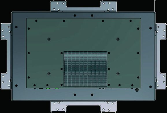
    Copyright
    The contents of this manual are subject to change without notice.
    © 2021 Distec GmbH. All rights reserved.
    Reproduction of this manual in parts or entirely without the previous authorization of Distec GmbH is prohibited.
    Distec GmbH is not liable for errors and collateral or subsequent damage which result from supply, deployment or any other utilisation of this document.
    All product names mentioned in this document are trademarks or registered trademarks of their due owners.

    2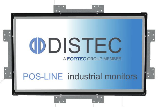
Table of Contents

1.     General Specifications................................................................................ 4

2.     Chassis Versions.......................................................................................... 5

3.     Scope of Delivery........................................................................................ 6

4.     General Safety Regulations........................................................................ 7

5.     First Installation......................................................................................... 10

6.     Touch Sensors............................................................................................ 14

7.     POS-Line Video PME.................................................................................. 15

8.     POS-Line IQ Atom...................................................................................... 23

9.     POS-Line IQ Core®-i................................................................................... 27

10. POS-Line VideoPoster................................................................................ 31

11. POS-Line IoT.............................................................................................. 36

12. WebPoster................................................................................................. 39

13. Maintenance............................................................................................. 41

14. Guarantee / Service.................................................................................. 41

15. Disposal..................................................................................................... 43

16. Declaration of Conformity......................................................................... 44

                                                                                                                        3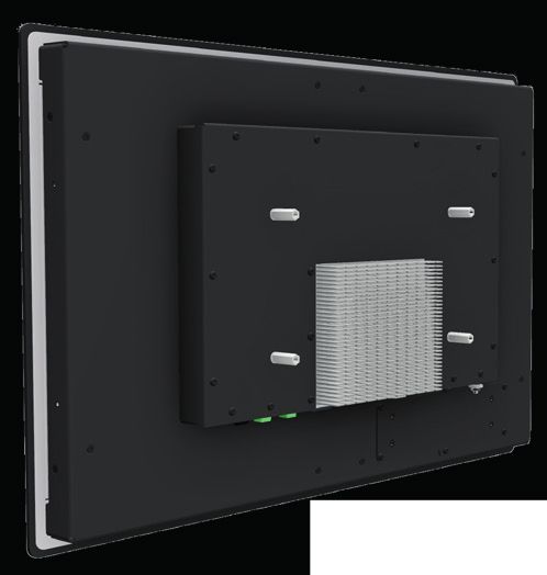
General Specifications

        1.        General Specifications

        Scope of Document

        This user manual is valid for POS-Line monitors up to 61 cm (24”). The POS-Line monitors are offered in different screen sizes and with
        various controllers and other options.

        Important note: All documents are available for download from Distec web site: https://www.distec.de/en/service/downloads/mon-
        itor-downloads/.

        POS-Line monitor versions:

        POS-Line Video PME:           Monitor with integrated AD converter board, 1 x RGB, 1 x HDMI, 1 x Display Port.

        POS-Line IQ Atom:		           Monitor with integrated PC board Intel Atom.

        POS-Line IQ Core-i7:          Monitor with integrated PC board Intel Core-i.

        POS-Line VideoPoster:         Monitor with integrated network media player for video play lists.

        POS-Line IoT:		               Monitor with integrated Raspberry® Pi CM3 ARM module.

        4
Chassis Versions
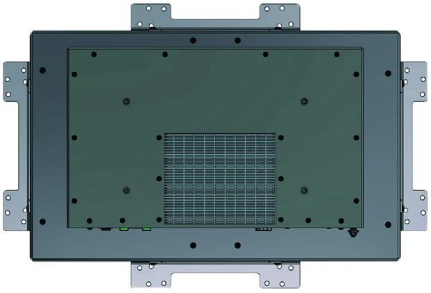
2. Chassis Versions
Various front options are available for the POS-Line displays to support the mounting in different situations and applications. The front
options changes the look of the displays.
Note: All the photos and graphic representations of this document show open frame displays. However, the explanations
apply also to displays with front bezel.
Displays with various front bezels:
Open frame display
(without bezel)
For mounting with angles or VESA com-
patible mounts.
Display with front bezel
For VESA compatible mounts.
Display with front plate
For front mount applications with angles
or VESA compatible mounts.
Display with true-flat glass
For front mount applications with angles
or VESA compatible mounts.
5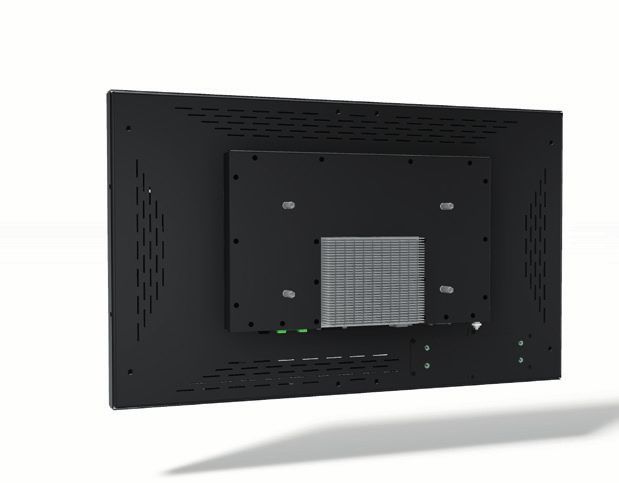
Scope of Delivery

        3.       Scope of Delivery

        When unpacking the monitor, please check if the following accessories are included in the shipment:

                 Note: Pictures can differ from actually supplied products.

        		                Product information

                         RGB cable***                      USB cable*                  Power adapter

                                USB stick**                  2 mounting brackets****

        *		      Devices with touch sensor only
        **		     POS-Line VideoPoster series only
        ***		    POS-Line PME series only
        ****		   Not together with option front bezel

        6
General Safety Regulations

4.        General Safety Regulations

Safety information

Please read this safety information carefully for your personal safety and for the prevention of property damage.

In case of a malfunction, immediately disconnect the power plug and contact your dealer or the next Data Display Group service cen-
tre. A malfunction is also considered if the housing, a control element or cable is damaged or if liquids or other objects penetrate the
monitor.

Please read the safety information carefully before installing the device. If you have any doubts about whether the device may be used
in a particular environment, please contact our service partner.

Repairs

Repairs may only be carried out by authorized technical personnel. Unauthorized access or improper repairs might cause serious prop-
erty damage or cause danger to the user. In addition to that, any legitimate warranty claim expires.

Electrical connection

Disconnect the monitor from socket before executing any work. Do not touch or connect data cables or power cables during thunder-
storms.

System start-up

Before the system start-up let the monitor adjust to the room temperature. Do not expose the device to direct heat sources. In case
of condensation, please wait a minimum of 12 hours before switching on the monitor. The monitor shall only be installed and used
according to this documentation data sheets. Only qualified personnel may perform the initial installation and system setup.

Qualified personnel

Qualified personnel, in terms of the safety information of this documentation, are persons who are qualified to activate, ground and
label devices, systems and circuits according to the safety standards.

Operation

For a proper and safe utilization of the product, adequate transportation, storage, installation, assembly, careful handling and main-
tenance are essential. The device is only certified for in-door operation. Extreme ambient conditions shall be avoided and the monitor
shall be protected from dust, humidity and heat. Do not expose the monitor to direct sunlight.

Transport

Unpack the monitor at the place of installation. Use only original packaging for transportation. Please observe these rules for any later
transport.

Condensation

Avoid condensation during transport at low temperatures or at extreme fluctuations of temperature.

                                                                                                                                       7
General Safety Regulations

                             Safety guidelines for the handling of LCD monitors

                             • If the device is not used for a long period of time, unplug the power cable.
                             • Do not unplug the power cable while the device is powerd on, except for emergencies.
                             • To unplug the device without problems, sockets have to be easily accessible.
                             • Ensure that the power cable does not get pinched or kinked.
                             • Do not place heavy objects on the power cable.

                             • Do not use damaged or loose sockets to plug in the device.
                             • Plug the device in secured sockets only.
                             • Operate the device with the power cables included in the delivery packet only.
                             • Use undamaged power cables only.
                             • When plugging in and out, do not touch the power cable with wet hands.
                             • Ensure that the power cable is plugged in the socket safely and correctly.
                             • Use for devices with external power supply only Low Power Source (LPS).

                             • Do not use extension block to plug several devices into a single socket.

                             • According to the size, devices may be difficult to handle and very heavy. Ensure that at
                               least two people lift and carry the device.
                             • Put down the device slowly and carefully to avoid damaging the LCD screen. Ensure that
                               the device stands stable.
                             • Keep packaging away from children. Danger of suffocation!
                             • Use our specified and professionally mounted wall mounting only.

                             •   Do not put objects onto the device.
                             • Do not place candles, heaters or humidifier near the device.
                             • Keep the device away from fireplaces and flammable materials.

        8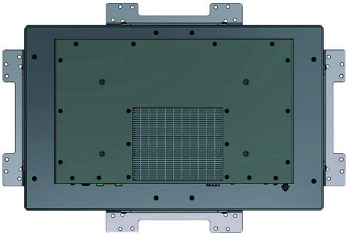
General Safety Regulations

• Ensure sufficient ventilation of the device.
• Keep a minimum distance of at least 10 mm devices to the wall, for devices with inte-
  grated PC of at least 40 mm.
• Ensure compliance with the operating temperature.

• Do not install the device in places where it is exposed to environmental impacts such
  as rain or direct sunlight.
• Do not install the device in places where it is exposed to high humidity, dust or smoke.
  In case of doubt, please contact your sales partner.

• Please use a soft, moist cloth for cleaning.
• For cleaning the screen, please use only commercially available screen cleaner. Do not
  spray the cleaner directly to the device but onto a cloth.
• Please clean ventilation slots regularly to ensure a good air circulation.
• Protect your device from water splash.
• When cleaning, please make sure that no liquids get into the device.
• Screens and surfaces can be easily scratched. Therefore, please use the prescribed
  cloth only.

• In case of unusual noises, burnt smell or smoke unplug the power cable.
• Do not insert objects into the device through the ventilation slots.
• If the same picture is displayed over a longer period of time, an after-image may arise.
• When exchanging batteries, pay attention to the polarity. Keep batteries away from
  children and ensure an environmentally correct disposal.

                                                                                         9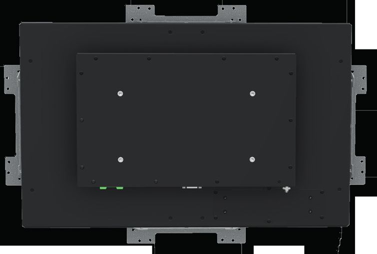
First Installation

         5.        First Installation

         Position of connectors and controls

         All the connectors for power and cables are located at the bottom of the back side of the display. The OSD keyboard (POS-Line Video
         series only) is located at the top of the back side.

         							                                                         Position of the OSD keyboard (Video series only)

         							                                                         Position of the connectors for power and signal cables

         Mounting with VESA compliant monitor brackets

                                                         VESA-Befestigungspunkte
         						VESA mounting points

         The POS Line monitors have an integrated VESA mounting.
         The operating position of the device is perpendicular (90 degrees to the floor). For wall mounting, the permissible tilt angle is observed.
         The device can be operated both in landscape mode and in portrait mode.

         VESA formats:
         VESA 200x100 POS Line

         10
First Installation
Mounting on wall
Distance to wall:
• devices without integrated PC: min.10 mm
• devices with integrated PC: min. 40 mm
oben
A
A: 50 mm D D
C
B: 50 mm
C: 10 mm/ 40 mm C
Ansicht von oben C: 10 mm/ 40 mm
D: 0 mm
B
unten
Seitenansicht
Allowed tilt angle for mounting
The following monitors may be mounted only with a tilt angle of 0˚ - +180°: monitor
• All monitors with true-flat glass or option true-flat PCAP touch
• All monitors with safety glass or option touchsreen ( with and without front
bezel)
The following monitors may be mounted only with a tilt angle of 0˚ to -180˚:
0˚ to +180˚ 0˚ to -180˚
• All monitors without safety glass, true-flat glass or option touchscreen
tilt angle
• All monitors with safety glass or option touchscreen (only in combination with
a front frame)
11First Installation
Connecting to Power
Note: The operating power of the POS-Line monitor depends on the choosen controller and on selected options. Please read
the lable regarding the power supply before connecting the monitor to the power.
Note: POS-Line V2 Monitors can be supplied with a suitable power supply from our accessories store. Please observe the
notes in the section “Connecting to an existing power supply”.
Depending on controller and on ordered options, POS-Line monitors have different power requirements. The following table lists all the
POS-Line versions and their operating power:
Monitor Version Operating Power Power Supply Included
min. typ. max.
POS-Line Video PME (for standard video signals
11.7 V DC 12 V DC 12.3 V DC no
VGA, HDMI, DP)
POS-Line IQ Atom/ Core-i 11.4 V DC 12 V - 24 V DC 27.3 V DC no
POS-Line VideoPoster 11.4 V DC 12 V DC 12.6 V DC no
POS-Line IoT 11.4 V DC 12 V DC 12.6 V DC no
Display Input voltage Output voltage Output current Power
Power supply für POS-Line
PME, VideoPoster, IoT, IQ Atom 100-240 V AC 12V DC 5A 60 Watts
and IQ Core-i
The power is connected to the display via the green female connector at the back side.
Female connector: Phoenix Contact DFK-MSTB-2,5 / 3-GF
Male plug: Phoenix Contact MSTB 2,5 / 3-STF
Connecting to power with optional power supply
Note: Connect the data cables to external devices before plugging the display to the power.
An adapter cable to connect the optional AC power adapter is included to all monitors in the package.
• Connect the adapter cable to the display.
• Connect the adapter cable to the 12 V connector of the power supply.
• Connect the power cable to the power supply.
• Connect the power cable to a power socket.
• Disconnect device: The AC main power supply can be disconnected via the Phoenix connector (DC), via the POS-Line V2 monitor or
the AC adapter’s plug.
Power supply
12V nc GND
12First Installation
Connecting to an existing power supply
Caution: POS-Line V2 monitors with an input voltage of 12V or 24V can only be used with a current source of limited power
(see standard EN 60950-1, chapter 2.5, table 2B “current source limited line” with max. 24V / 4A 100VA).
• Make sure that your external power supply is sufficient for the display. The maximum power consumption of the display is indicated
in the data sheet and the display label.
• Disconnect the adapter cable, if necessary, the device and the power supply.
• Disconnect the green connector from the adapter cable.
• Connect your POS-Line monitor to your power source. Pay attention to polarity of the green connector!
• Connect the green connector to the device.
• Disconnector: The DC supply network can be disconnected via the Phoenix connector, at the POS-Line V2 monitor.
GND
Power supply
+12V
12V nc GND
Grounding the display chassis
The housing of the monitor is equipped with a function grounding. This can be connected optionally to the earthing of the system. Use
the connector on the bottom of the monitor as well as a ground cable with a sufficient cross-section (for example 0.75 mm²).
13Touch Sensors
6. Touch Sensors
POS-Line monitors are available with touch option. Depending on the panel size, different touch systems and touch technologies are
used. If the monitor has been ordered with touch option, the touch sensor and touch controller are installed at factory.
POS-Line IQ:
The actual touch driver is pre-installed on these systems if ordered with operating system. The touch can be put directly into operation.
POS-Line Video:
The drivers for these monitors must be installed on your PC system. HID devices do not need drivers for Windows 7 and higher. Please
contact our support center if you are using LINUX based computers.
If a driver is required, the touch on this driver must be calibrated. Is it a HID Touch, Windows calibration in the control panel must be
performed.
path:
Control Panel \ All Control Panel Items \ Tablet PC Settings
Note: All drivers for the touch sensors can be found on our website: https://www.distec.de/en/service/down-
loads/monitor-downloads/. The following table gives an overview over the touch systems including web ad-
dresses for driver downloads.
Touch system overview:
Panel size Touch technology Driver download
15” 5-wire resistive http://home.eeti.com.tw/web20/eg/Touch_Drives.html
17“ 5-wire resistive http://home.eeti.com.tw/web20/eg/Touch_Drives.html
17.3“ P-CAP http://home.eeti.com.tw/web20/eg/Touch_Drives.html
19“ 5-wire resistive http://home.eeti.com.tw/web20/eg/Touch_Drives.html
21.5” P-CAP http://home.eeti.com.tw/web20/eg/Touch_Drives.html
24” P-CAP http://home.eeti.com.tw/web20/eg/Touch_Drives.html
14POS-Line Video PME
7. POS-Line Video PME
Connectors and OSD buttons of POS-Line Video PME series
Keyboard
OSD Tastatur
LED
Power supply DisplayPort HDMI VGA (RGB) USB (remote OSD) Line out USB (Touch)
12V nc GND
Connecting to a PC with VGA cable
VGA (RGB) VGA (RGB)
Connecting to a PC with HDMI-DVI cable
HDMI DVI
Connecting to a PC with HDMI cable
HDMI HDMI
15POS-Line Video PME
Connecting to a PC with DisplayPort cable
DisplayPort DisplayPort
Connecting the Remote-OSD to a PC with USB cable
USB (remote OSD) USB
Connecting the touch to a PC with USB cable (for displays with touch sensor only)
USB (Touch) USB
Connecting active speakers with audio cable
Line-out Line-in
16POS-Line Video PME
Remote OSD control
To control the OSD menu of the display remotely from a PC, use a USB cable and connect the display to your PC as described above.
Please read the handbook for the remote control carefully. The handbook can be found in folder ‘Remote-OSD’ of the attached CD. The
document describes in detail all the commands and the structure of the commands for the serial interface.
OSD keyboard
The OSD functions of the monitor can be controlled via OSD key pad. The OSD allows the selection of the input source and the fine
tuning of various functional parameters like brightness, contrast etc.
OSD Tastatur
LED
The six buttons of the OSD control can either be used:
• To access various functions directly
• To navigate within the OSD
The following two tables give an overview of the functions:
Direct functions:
Key Function Comment
Menu Open the OSD menu
— Open volume control
+ Open brightness control
Exit Select signal input
Power On/ Off
Navigation in OSD menu:
Key Function Comment
Open sub menu when in main
Menu
Confirm entry when in main
Cursor down when in main or in sub menu
—
Cursor/ slider to the left when in main or in sub menu
Cursor up when in main or in sub menu
+ Cursor/ slider to the right when in main or in sub menu
Leave OSD menu when in main
Exit
Leave sub menu when in sub menu
17POS-Line Video PME
The green/red LEDs (single package) on the external keypad show the current status of the board:
Color Meaning Remark
Green Signal found
Green blink Search signal
Red Power safe mode
LED off Monitor off
OSD menu
Image Menu
Brightness: Panel brightness adjustment.
Contrast: Panel contrast adjustment.
Hue: Panel hue adjustment.
Saturation: Panel saturation adjustment.
Sharpness: Panel sharpness adjustment.
Color: Opens the color sub menu.
Color Sub Menu
Auto: Performs auto color adjustment.
Color Temp: Allow selection of different color temperature
schemes, predefined and custom. Available if color
space of input is RGB.
Full color: Selects full received color space.
SRGB: Selects SRGB color space.
XVYCC: Selects XVYCC color space.
18POS-Line Video PME
Display Menu
Auto-adjust: Performs auto-adjustment on the VGA input image.
Phase: This function is a slider to adjust the sampling
phase of the analogue interface. For optimum image
quality, input pixels should be sampled at the ideal
sampling points.
Clock: This function is a slider to adjust the sample clock of
the analogue interface. This is helpful for improving
the image quality for non-standard display modes.
Position: Used to modify the placement of the image.
Move Position Sub Menu
Arrows: Use arrow keys to move the position of the image
on the screen.
19POS-Line Video PME
Sound Menu
Volume: Slider bar to adjust volume.
Mute: Mutes audio.
Output: Chooses between speakers and headphone. Only
one can be active at a time (Speakers are not avail-
able for POS-Line monitors).
Output Sub Menu
Speakers: Toggles speakers on/ off.
Headphone: Toggles headphone on/ off.
System Menu
Input source: Sub menu to select input source.
OSD settings: Sub menu for OSD settings.
Factory reset: Sub menu for Factory Reset.
EDIT settings: Sub menu for EDIT settings.
FW Revision: Firmware revision.
OSD Revision: OSD revision.
20POS-Line Video PME
Input Sub Menu
Display Port: Select display port as input signal.
VGA: Select VGA as input signal.
DVI/HDMI: Select DVI/ HDMI as input signal.
Auto Scan: Enable/ disable input auto-scan.
OSD Settings Sub Menu
Timer: Sub menu for timer settings.
Rotation: Sub menu for rotation settings.
Position: Sub menu for image position.
Transparency: Slider to set transparency.
Timer Sub Menu
Timer: Selects how many seconds the OSD will remain
active after the last use.
21POS-Line Video PME
Rotation Sub Menu
Rotation: Rotates the OSD menu.
Reset Sub Menu
Reset: Performs factory reset.
EDID Write Protect Sub Menu
Write protect: EDID write protect on/ off.
22POS-Line IQ Atom
8. POS-Line IQ Atom
Note: All the Atom main board drivers you can find at: https://www.distec.de/en/service/downloads/monitor-downloads/
Note: This POS-Line display is equipped with a battery. Please read the following instructions carefully:
• Unplug the power cable before exchanging the battery.
• There is a risk of explosion if the battery is not installed correctly.
• Replace the battery always with a battery of the same type.
• Recycle empty batteries with the free battery collection system. Please read the chapter “Disposal” of this document.
Note: If the option DS-91-823 is installed, the RS232 cable used at this interface (optional) may have a maximum length of 3.0
meters.
Passive cooling
The POS-Line displays of the IQ Atom series (integrated PC) are with passive cooling (fan-less).
Passively cooled monitors conduct heat from the processor to the monitor housing. Passively cooled devices have no moving parts..
PC specifications
Please inform yourself current data sheet about the details of the PC specification of the IQ Atom.
Connectors of POS-Line IQ Atom series
optional
Power supply LED RS232 VGA (RGB) 2 x USB 2 x LAN Button RS232
HDMI
12V nc GND
LED-display
• upper LED lights yellow - HDD active
• lower LED lights green - power on
23POS-Line IQ Atom
Connecting to a network using a patch cable
LAN LAN
Connecting to a PC using a cross-over cable
LAN LAN
Connecting keyboard and mouse with USB cable
USB
USB
Connecting an external monitor with HDMI cable
HDMI HDMI
24POS-Line IQ Atom
Connecting an external monitor with VGA cable
VGA (RGB) VGA (RGB)
Connecting an external PC with RS232 cable (optinally)
RS232 RS232
Power on/off
The display boots automatically after connecting to the power. Use the push button to switch the display on and off. If switched on,
push the push button once to shut down the system. The panel is switched off. If switched off, push the push button once to turn on
the display.
Button
25POS-Line IQ Atom
BIOS settings
A BIOS from American Megatrends Inc. (AMI BIOS) is installed on the PC main board. To change BIOS settings press the ‘DEL’ or ‘F2’
key on your keyboard during the boot process of the PC.
Operating systems
An operating system is pre-installed if your POS-Line display has been ordered with this option. In this case all main board drivers or
touch drivers are installed.
Activating the operating system:
• Windows 10 IOT: This OS is already activated. The license key sticker can be found on the back side of the display.
• Windows 10: This OS is not activated. The license key sticker is added to the product documentation. After switching on the display
for the first time Windows will prompt for the key.
26POS-Line IQ Core®-i
9. POS-Line IQ Core®-i
Note: All the main board drivers you can find at: https://www.distec.de/en/service/downloads/monitor-downloads/
Note: This POS-Line display is equipped with a battery. Please read the following instructions carefully:
• Unplug the power cable before exchanging the battery.
• There is a risk of explosion if the battery is not installed correctly.
• Replace the battery always with a battery of the same type.
Passive cooling
The POS-Line displays of the IQ COre-i7 7th gen.series (integrated PC) are with passive cooling (fan-less).
Passively cooled monitors conduct heat from the processor to the monitor housing. Passively cooled devices have no moving parts.
PC specifications
Please inform yourself current data sheet about the details of the PC specification of the IQ Core-i7 7th gen..
Connectors of POS-Line IQ Core®-i7 7th gen. series
buttom Power supply 2 x LAN USB 2 x 3.0 USB 2 x 3.0 RS232
DisplayPort
HDMI
12V nc GND
27POS-Line IQ Core®-i
Connecting to a network using a patch cable
LAN LAN
Connecting to a PC using a cross-over cable
LAN LAN
Connecting keyboard and mouse with USB cable
USB
USB
Connecting an external monitor with HDMI cable
HDMI HDMI
28POS-Line IQ Core®-i
Connecting an external monitor with DisplayPort cable
DisplayPort DisplayPort
onnecting an external PC with RS232 cable
RS232 RS232
Power on/off
The display boots automatically after connecting to the power. Use the push button to switch the display on and off. If switched on,
push the push button once to shut down the system. The panel is switched off. If switched off, push the push button once to turn on
the display..
Button
29POS-Line IQ Core®-i
BIOS settings
A BIOS from American Megatrends Inc. (AMI BIOS) is installed on the PC main board. To change BIOS settings press the ‘DEL’ or ‘F2’
key on your keyboard during the boot process of the PC.
Operating systems
An operating system is pre-installed if your POS-Line display has been ordered with this option. In this case all main board drivers or
touch drivers are installed.
Activating the operating system:
• Windows 10 IOT: This OS is already activated. The license key sticker can be found on the back side of the display.
• Windows 10: This OS is not activated. The license key sticker is added to the product documentation. After switching on the display
for the first time Windows will prompt for the key.
30POS-Line VideoPoster
10. POS-Line VideoPoster
Note: Further information on media player, play list structure, handling, utilization and supporting software modules are
available at
https://www.distec.de/en/products/tft-controller/industrial-media-players/
Note: This Gerhardt display is equipped with a battery. Please read the following information carefully:
• Unplug the power cable before exchanging the battery.
• There is a risk of explosion if the battery is not installed correctly.
• Replace the battery always with a battery of the same type.
• Recycle empty batteries with the free battery collection system. Please read the chapter “Disposal” in this document.
Connectors of POS-Line VideoPoster series
Power supply LAN USB USB MicroSD card Reset Button Line-out HDMI IN
12V nc GND
Connecting to a network using a patch cable
LAN LAN
31POS-Line VideoPoster
Connecting to a PC using a cross-over cable
LAN LAN
Connecting an USB stick
USB
Connecting active speakers
Line-out Line-in
Connecting a signal source using a HDMI cable
HDMI HDMI
32POS-Line VideoPoster
Connecting a signal source using a HDMI-DVI cable
HDMI DVI
Factory configuration at the time of delivery
POS-Line VideoPoster is a network (Ethernet) device. Please note that inaccurate network configuration can have unintended influence
on network operations and cause a breakdown of the entire network. To setup the device properly, you must be familiar with the basic
operating parameters of your network.
Factory configuration of POS-Line VideoPoster at time of delivery:
• DHCP: on
• IP-Address: assigned by DHCP server (fallback to static IP address 192.168.0.1, if no DHCP server is available in the
network)
• Netmask: assigned by DHCP server (fallback to 255.255.255.0, if no DHCP server is available in the network)
• Hostname: Videoposter-IV-xx-xx-xx (last 6 bytes of the devices MAC address)
• Login Name: Artista
• Password: Artista
• Content auto update: off
MicroSD Card
The Mediaplayer stores its playlists on the internal 2GB memory. A microSD card, however, can be extended, if the internal memory is
not enough. If a microSD card is plugged in, it must not be removed during operation!
Supported media formats
Video:
• MPEG-4 AVC / H.264
• Quicktime
• Flash Video
• MPEG Transport Stream
Still images:
• PNG
• JPG
• BMP
33POS-Line VideoPoster
Functional description
POS-Line VideoPoster is a networked stand alone media player to playback play lists. Operating systems or other client-based software
components are not required. Play lists are based on a XML structure and can include videos and images. The media player controlls
the play list. A play list is looped endlessly until a new play list is loaded or the player is switched off. A play list may contain several
sub play lists which can be triggered by an internal timer or other external events like push buttons or proximity switches (optional
external I/O board).
POS-Line VideoPoster does not need any local operation. As soon as a play list is loaded, the media player will automatically start
with playback. Power can be switched off at any time, a shut down procedure is not required. After power on, the media player will
automatically playback the current play list.
Connecting an external source with priority
An external source like video player or sat receiver can be connected to the POS-Line VideoPoster via HDMI. If priority of the HDMI
connector has been activated, the playback of the play list will stop as soon as a HDMI signal is detected. In this case, the HDMI signal
is shown on the screen. If the external player is switched off, the media player will automatically start or continuing playing back the
internally stored play list.
Software
The following software and accompanying documentation were made available to you by e-mail:
ACC: Windows software to create play lists for POS-Line VideoPoster devices. Use ACC to transfer play lists to VideoPoster, and to
store play lists on USB sticks for manual transfer.
ADF: Windows software to support installation and configuration of VideoPoster devices. Connect your VideoPoster as shipped (factory
configuration) to the network. ADF will detect all VideoPosters and allow an easy configuration of the network parameters.
Downloading play lists
There are basically four methods to download play lists:
Via USB: If a USB stick with a playlist is inserted into the Mediaplayer, it is loaded and started automatically. In this operating mode,
a network connection is not necessary..
Via ACC: This is a free software for Windows to create play lists and to upload play lists to one or more media player in the network.
Via FTP Server: The media player connects to a FTP server in configurable time intervals and searches for new playlists. The differences
between the existing and the new playlist are loaded automatically and playback of the new content starts.
Via HTTP-Protocol: Use HTTP protocol to transfer and control VideoPoster from any existing Content Management System.
Configuration
Use any Internet browser like Firefox, Internet Explorer, Chrome, etc. for the configuration of the VideoPoster. Enter the URL (i.e. IP
address or network device name) to open the device‘s web interface. Please enter the password if required (factory settings: Login
name: Artista; Password: Artista).
34POS-Line VideoPoster
Layout of the web interface:
Information
System Information:
Here you can find all the information about the system like software revision. In case of a support
request please add a printout of this page to your mail for a fast processing.
View Logs: VideoPoster creates log files to allow an easy monitoring of operations. The following log
files are available:
Player – shows the log file of the video player and error messages.
Updater – shows the log file of content updates and error messages.
Setup Manager – shows the list of executed setup files.
Event Manager – shows error messages of the event manager.
Configuration
Network Configuration: This page includes all entries for the network configuration. Click on „Submit Configuration“ to store
the settings and change the configuration. Clicking on „Reset Configuration“ deletes all entries in the
web page but does not change the configuration.
Date and Time: Enter date, time and time zone. Enter a network time server for automatic synchronization (NTP).
Content Auto Update: To configure automatic content updates with FTP server, enter the FTP server access information and
update time interval here.
Audio Settings: Volume settings for speakers.
Display Settings: Panel brightness settings.
HTTP Access: Enter password. It is recommended to change the password after installation.
Advanced: Firmware updates, microSD card (optinal) formating,reset of hardware configuration to factory defaults
and priority setting for HDMI input.
Restart
Restart: Media player restart.
On-screen display of IP-address and host name
IP-address and host name are shown on the screen for 5 seconds during the boot process.
35POS-Line IoT
11. POS-Line IoT
The POS-Line IoT monitor is equipped with the Raspberry® Pi compute module 3 (CM3). The specification can be found under the
following link:
https://www.raspberrypi.org/products/compute-module-3/
Note:
The full driver package for the IoT monitor can be found an: https://www.distec.de/en/service/downloads/monitor-down-
loads/.
The device is equipped with a battery. Please note the following:
• Disconnect the devise from the power supply before replacing the battery.
• If the battery is not replaced properly there is a risk of explosion.
• Always replace the battery with another one of the same type.
• Supply empty batteries to the local waste battery return system. Please also observe the notes in chapter „Disposal“.
Passive cooling
Monitors of the POS-Line IoT series are equipped with a passive cooling system. Passively cooled monitors divert the heat of the
processor to the monitor‘s housing. Passively cooled devices have no moving parts.
Spezification
Please refer to the current data sheet for the details of the IoT monitor specification.
Connectors of POS-Line VideoPoster series
Power supply LAN USB USB MicroSD card Reset Button Line-out HDMI IN
12V nc GND
Connecting to a network using a patch cable
LAN LAN
36POS-Line IoT
Connecting to a PC using a cross-over cable
LAN LAN
Connecting to an USB stick
USB
Connecting active speakers
Line-out Line-in
Connecting a signal source using a HDMI cable
HDMI HDMI
37POS-Line IoT
Connecting a signal source using a HDMI-DVI cable
HDMI DVI
Switch on/ off
After the supply voltage has been applied, the IoT monitor starts automatically. To switch off, you must select „Shut down“ in the
operating system.
Operating systems
The IoT Monitor comes with the operating system Raspbian, which is equipped with all necessary drivers. This operating system is the
official version of the community, reduced to the internal memory of the compute module. It is only used for the first commissioning of
the monitors.
The IoT Monitor can be equipped and programmed by the customer with its own operating system/ image. For this, the USB port on the
back of the monitor can be used, which is located under the black sticker on the cover (arrow).
A guide for the integration of an image can be found on the enclosed DVD or on our homepage:
https://www.distec.de/en/products/tft-controller/iot-industry-40-raspberry/
In the community of Raspberry® Pi (https://www.raspberrypi.org/forums/) you can find many problem-solving and help to integrate and
create your own system.
38WebPoster
12. WebPoster
Connections and controls
WebPoster are POS-Line IQ Atom devices with a special firmware, so the ports and operating in the „IQ Atom“ must be observed.
Connecting a mouse and keyboard is not supported with this firmware.
Functional description
The Industrial HTML Full HD Player is a complete solution for viewing Web pages. The website can be configured via a web interface.
At the start of the device is automatically display.
Configuration of the media player on delivery (factory configuration)
This device is a LAN (Ethernet) enabled device. Please note that an incorrect network configuration the device may affect the safe
operation of the entire network and in the worst case of a network failure leads. To set up the device for a specific network, you need
the key operating parameters of the network be known. The POS Line WebPoster is shipped from the factory with the following con-
figuration:
• DHCP: on
• IP-Address: 192.168.0.1*
• Netmask: 255.255.255.0
• Hostname: WebPoster-xx-xx-xx (the last 6 bytes of the MAC address of the device)
• Login Name: Artista
• Password: Artista
*If no DHCP server is found, this IP address is assigned automatically.
Supported site formats
• HTML5
• JavaScript
Software
On the enclosed disk contains the following software and related documentation.
ADF: A program that simplifies the installation and configuration of HTML players. Connect any HTML player in the factory configu-
ration to the network and start ADF. It displays all the HTML players in a list. Select the devices one by one and remove the network
configuration.
Configuration of the media player
The configuration of the HTML player can work with any standard web browser (Firefox, Internet Explorer, Chrome, etc.) are performed.
Connect the HTML player to a network and enter to establish the connection URL (eg. as IP address or network name) in the browser.
Now open the WEB interface. If you are prompted for the password, enter the password (factory setting: Login name: Artista; pass-
word: Artista).
Layout of the web interface::
Configuration
Network Configuration: The configuration of the network is the first step in setting up.
Submit Configuration: With Submit Configuration the entries will be accepted.
Discard Changes: With Discard Changes be deleted entries in the fields.
However, this has no influence on the current configuration.
Browser Settings: The configuration of the Web page to display is the second step of the device.
Here the web page can be entered and a „Reload Interval (seconds)“ can be defined.
Submit Configuration: With Submit Configuration the entries will be accepted.
Discard Changes: With Discard Changes be deleted entries in the fields.
Change Password: Here, the default password can be changed.
39WebPoster
Information
System Information: This page contains all details about the system, such as, for example, the software version.
If you contact our Support please add this page to your E-Mail to ensure a fast response.
Restart
Restart: Restart of the media player.
Display of IP address and hostname
When booting the HTML player‘s current IP address and the host name of the HTML player is displayed on the screen for about 5
seconds.
40Maintenance
13. Maintenance
Systems with active cooling require cleaning of ventilation slots every 6 months. Systems with passive cooling must be cleaned every
12 months.
14. Guarantee / Service
Guarantee
Fortec Group grants a manufacturer‘s guarantee of two years from the date of delivery.
The rendering of guarantee claims shall neither extend nor restart the guarantee period.
During the guarantee period, Fortec Group shall repair product faults based on material or production defects. The guarantee service is
executed at Fortec Group‘s discretion through repair, replacement of defective parts or by exchanging a product for a product of equal
quality without charging the customer for material or labor.
Guarantee claims are only accepted, if Fortec Group receives notification of a defective product within the guarantee period and the
product is presented to the Fortec Group Service Centre together with all information as specified in the RMA process.
Guarantee Exclusions and Limitations
This guarantee does not apply to any defect for which Fortecy Group is not responsible and which includes, but is not limited to the
following:
• Unauthorized opening or disassembling of the product
• Faulty maintenance by non-observation of maintenance instructions
• Inappropriate storage or cleaning of the product
• Unauthorized modification of the product
• Incorrect use or misuse
• Non-observation of operating and installation instructions
• Permanent display of fixed images (causing image retention or image sticking)
• Operating the product in conditions which exceed the limitations of the specification
• Use of inappropriate boxes, packaging or modes of shipment
• Force majeure like fire, acts of war, acts of violence, chemical or biological impacts, lightning strikes, over voltage or
similar events
• Fault resulting from the use of software which was not originally supplied with the product or which is incorrectly installed
• Normal wear and tear and wearing parts (i.e. LCD panel)
Mechanical damages like scratches, pressure or break points are excluded from this guarantee.
This guarantee does not include accessory parts which are not integral part of the product (as boxes, batteries).
Pixel errors only constitute a fault under the terms of this guarantee if they deviate from the product specification (i.e. ISO 9241-307
pixel failure class II).
41Guarantee / Service
Display Quality - Prevention of after image burn in effects
After image burn-in means that an image or part of an image (i.e. logo) remains visible on the screen even if the image on the screen
is changed. This should not occur if the LCD panel is operated in normal conditions with changing content. To prevent burn-in effects
please follow the following guidelines.
• Do not display fixed patterns for an extended time period of more then 12 hours.
• Power-off the monitor for 4 hours after using it for 20 hours, and for 2 hours after using it for 12 hours.
• Use the power scheme and power management of the PC.
• Use plain-colored screen savers.
• Avoid patterns with a strong difference in brightness and contrast.
• Avoid gray colors.
• Change images and logos regularly. Show animated pictures for 60 seconds after 4 hours of operation.
• The best way to protect your display is to switch the monitor off when not in use or to use screen savers.
Non-observance of these guidelines may have effects on warranty.
Guarantee Processing
Group RMA process. In order to avoid unnecessary charges, it is important to adhere to the RMA regulations.
Products must be appropriately and professionally packed for a safe return to the Fortec Group Service Centre. Products with panel
sizes equal or larger then 81 cm (32“) must be shipped on pallets in upright position.
Fortec Group does not assume liability for any customer data stored on products which are returned to Fortec Group.
Limitations of Liability and Benefits
With this guarantee declaration, Fortec Group exclusively guarantees that the product is free of material and manufacturing faults.
Fortec Group does not issue any other guarantee or similar statements other than this declaration.
This guarantee does not impair or affect a buyer‘s statutory claim against the seller due to material damage. Such claims can be as-
serted instead of the guarantee agreed to here at the buyer’s discretion.
Mandatory legal rights and mandatory claims under the German Product liability remain unaffected.
Applicable Law and Place of Jurisdiction
The laws of the Federal Republic of Germany apply.
Place of jurisdiction is Munich.
Service addresses
42Disposal
Germany Great Britain USA
Distec GmbH - Werk Kindel Display Technology Ltd. Apollo Corp.
Am Künkelhof 4 Osprey House, 1 Sprey Court 87 Raynor Avenue, Unit 1
99820 Hördelberg-Hainich Hichingbrooke Business Park Ronkonkoma NY 11779
Huntingdon, Cambridgeshire PE29 6FN
T +49 3 69 20 71 62-0 T +1 63 15 80-43 60
T +44 14 80 41 16 00
B support@distec.de B info@displaytechnology.co.uk B info@apollodisplays.com
Please go to the following web address for further information about our RMA regulations and RMA forms:
Http://www.distec.de/en/service
15. Disposal
Disposal of old devices
If the acquired Distec product is to be disposed of, must be implemented into national law the Directive
2012/19/EU.
Disposal of batteries
Applicable in all countries of the EU and in countries with separate battery collection systems.
The Batteries in this product should not be disposed with other household waste. The chemical symbol
Pb, CD or Hg indicate that the battery contains lead, cadmium or mercury above the reference level in EC
directive 2006/66/EG.
Batteries which are not disposed correctly can cause harm environment and health.
Our environment is close to our hearts. Please help us to protect our environment and recycle empty bat-
teries with the free battery collection system.
43Declaration of Conformity
16. Declaration of Conformity
Declaration
Hereby the Distec GmbH declared that the unit EU is in compliance with the essential requirements and other relevant provisions of
Directives 2014/30/EU and 2011/65/EU.
The CE declaration of conformity can be found in English on the website: https://www.distec.de/en/service/downloads/monitor-down-
loads/.
FCC-Declaration of conformity
This equipment has been tested and found to comply with the limits for a Class A digital device, pursuant to Part 15 of the FCC Rules.
These limits are designed to provide reasonable protection against harmful interference when the equipment is operated in a commer-
cial environment. This equipment generates, uses and can radiate radio frequency energy and, if not installed and used in accordance
with the instruction manual, may cause harmful interference to radio communications. Operation of this equipment in a residential area
is likely to cause harmful interference in which case the user will be required to correct the interference at his own expense.
Canadian Department of Communications Compliance Statement
This Class A digital apparatus meets all requirements of the Canadian Interference-Causing Equipment Regulations.
Observation des normes-Class A - Cet appareil numérique de la classe B est conforme à la norme NMB-003 du Canada.
FCC Information:
• Changes or modifications not expressly approved by Distec GmbH could void the user’s authority to operate the equipment.
• Use the attached specified cables with the POS-Line monitor so as not to interfere with radio and television reception.
• Please use the supplied power cord or equivalent to ensure FCC compliance.
• Please use the supplied shielded video signal cable, Mini D-SUB 15 pin to Mini D-SUB.
44You can also read


