MARINE ACCIDENT INVESTIGATION REPORT - MA2020-7
←
→
Page content transcription
If your browser does not render page correctly, please read the page content below
MA2020-7

  MARINE ACCIDENT
INVESTIGATION REPORT

      August 27, 2020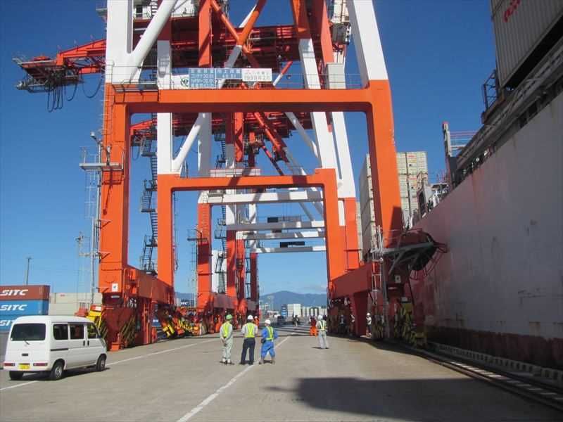
The objective of the investigation conducted by the Japan Transport Safety Board in
accordance with the Act for Establishment of the Japan Transport Safety Board is to determine the
causes of an accident and damage incidental to such an accident, thereby preventing future accidents
and reducing damage. It is not the purpose of the investigation to apportion blame or liability.

                                                              TAKEDA Nobuo
                                                              Chairperson
                                                              Japan Transport Safety Board

                                                     Note:
          This report is a translation of the Japanese original investigation report. The text in Japanese
shall prevail in the interpretation of the report.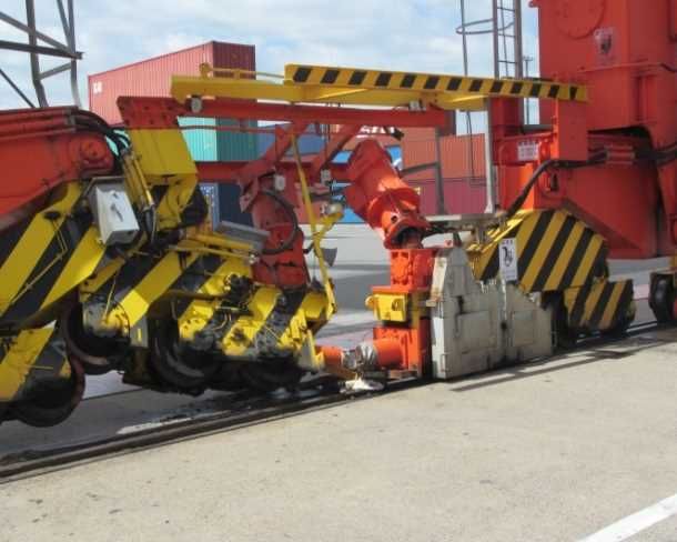
MARINE ACCIDENT INVESTIGATION REPORT

 Vessel type and name:   Container vessel OOCL NAGOYA
 IMO number:             9445538
 Gross tonnage:          40,168 tons

 Accident type:          Collision
 Date and time:          Around 07:39, August 17, 2018 (local time, UTC+9 hours)
 Location:               No. 26 berth of Kasumigaura-Minami Wharf, Yokkaichi Port,
                         Yokkaichi City, Mie Prefecture
                         Around 149° true bearing, 480 m from Yokkaichi Port Management
                         Association Kasumigaura No.1 range light (front light)
                         (Approximately 34° 59.5 'N, 136° 39.9'E)

                                                                              July, 15, 2020
                                              Adopted by the Japan Transport Safety Board
                                                     Chairperson     TAKEDA Nobuo
                                                     Member          SATO Yuji
                                                     Member          TAMURA Kenkichi
                                                     Member          KAKISHIMA Yoshiko
                                                     Member          OKAMOTO Makiko

                                       SYNOPSIS

< Summary of the Accident >
  The Container vessel, OOCL NAGOYA, which was manned by the Master and 23 other
crewmembers, was navigated under escort by the pilot's pilotage, while the vessel was
proceeding toward west and was approaching for berthing port side head-in to No. 26 berth of
Kasumigaura-Minami Wharf, No. 3 district of Yokkaichi Port on Yokkaichi City, Mie
Prefecture. At around 07:39 on August 17, her port fore collided with a gantry crane on the
berth.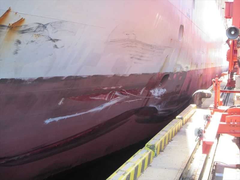
OOCL NAGOYA caused damage of cutting and bending at the bulwark of the port fore part,
etc.
     No. 26 berth of Kasumigaura-Minami Wharf caused damage of delamination at the concrete
construction, derailing and deformation at the gantry cranes, etc. but there were no casualties
in OOCL NAGOYA or the port facility.

< Probable Causes >
     It is considered probable that this accident occurred, at Yokkaichi port, under conditions a of
northwesterly wind blowing at wind force 5 to No. 26 berth of Kasumigaura-Minami Wharf,
No. 3 district of Yokkaichi Port on Yokkaichi City, Mie Prefecture, while the Container vessel,
OOCL NAGOYA was approaching No. 26 berth for mooring port side head-in by the Pilot's
pilotage instruction, and then the Master intervened immediately and conducted maneuvering
the vessel himself, and forward movement of the vessel was lost due to using by full astern,
because the vessel was swept away toward a car carrier which was moored for starboard side
head-out with her port side to No. 25 berth closely, and then taking full ahead was conducted
to avoid collision with the car carrier and the vessel was proceeding forward; however, the
vessel was not able to control her attitude, with the result that the port fore part of the vessel
collided with the gantry crane (S2 Unit) on No. 26 berth.
     It is considered probable that the Master intervened immediately and conducted
maneuvering the vessel himself, and forward movement of the vessel was lost due to using by
full astern, because the Master was not able to make sufficient trusting relationship with the
Pilot and felt that the approaching ship speed toward No. 26 berth was fast near the car carrier
moored at No.25, and thereby the Maser thought he would abort the vessel movement
completely.
     It is considered probable that the Master was not able to make sufficient trusting
relationship with the Pilot, because the Master felt that the Pilot’s explanation was not
sufficient for him.
     It is considered probable that the accident was occurred by involving in lack of BRM*1
including effective communication, etc. in the navigation bridge between the bridge team
including the Master and the Pilot, while the vessel was in a situation of being imminently
swept away toward the port side where No. 25 berth and the car carrier moored at No.25 were
located by the leeway exceeding 10°.

*1     “BRM (Bridge Resource Management)” refers to the effective management of crewmembers, equipment,
     information, and other available resources on the bridge to maintain and improve operational functions on
     the bridge.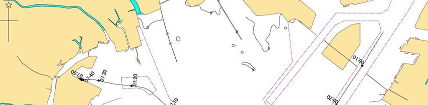
1 PROCESS AND PROGRESS OF THE INVESTIGATION

1.1 Summary of the Marine Accident
  The Container vessel, OOCL NAGOYA, which was manned by the Master and 23 other
crewmembers, was navigated under escort by the pilot's pilotage, while the vessel was
proceeding toward west and was approaching for berthing port side head-in to No. 26 berth of
Kasumigaura-Minami Wharf, No. 3 district of Yokkaichi Port on Yokkaichi City, Mie
Prefecture. At around 07:39 on August 17, her port fore collided with a gantry crane on the
berth.
  OOCL NAGOYA caused damage of cutting and bending at the bulwark of the port fore part,
etc.
  No. 26 berth of Kasumigaura-Minami Wharf caused damage of delamination at the concrete
construction, derailing and deformation at the gantry cranes, etc. but there were no casualties
in OOCL NAGOYA or the port facility.

1.2 Outline of the Marine Accident Investigation
 1.2.1 Set up of the Investigation
         The Japan Transport Safety Board (JTSB) appointed an investigator in-charge and other
       one marine accident investigator to investigate this accident on August 21, 2018.

 1.2.2 Collection of Evidence
         August 22, 2018: Interviews and collection of questionnaires
         August 23, 2018: On-site investigations, interviews and collection of questionnaires
         August 25 and 31, September 6 and 7, October 25, November 1,2018, and May 10, June
       20, July 31, 2019: collection of questionnaires.
         February 5 and 6, March 7, 2019: Interviews

 1.2.3 Comments of Parties Relevant to the Cause
         Comments were invited from parties relevant to the cause of the accident.

 1.2.4 Comments from the Flag State
         Comments were invited from the flag states of OOCL NAGOYA.

                                                  - 1 -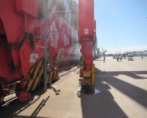
2 FACTUAL INFORMATION

2.1. Events Leading to the Accident
     2.1.1 Navigation Progress Traced by the Automatic Identification System
         According to the records of the Automatic Identification System (AIS)*2 data (hereinafter
       referred to as "the AIS record") received by a data company in Japan, the navigation tracks
       of "OOCL NAGOYA" (hereinafter referred to as "the Vessel") from 06:10 to 07:41 on August
       17, 2018, were as shown in Table 2.1-1 below.
         Changes in heading, course to ground, and ground speed from 07:20:03 to 07:40:04 in the
       AIS record were as shown in Figure 1.
         The positions of the Vessel are the position of the GPS antenna mounted above the
       navigation bridge respectively. The course over the ground and the heading were the truth
       bearings (same as hereinafter).

                             Table 2.1-1 AIS Record of the Vessel (abstract)
                                   Vessel position       Heading      Course Over                  Speed Over
        Time
                          Latitude (N)      Longitude(E)              the Ground                  the Ground*3
     (HH: MM: SS)
                              (°-′-″)            (°-′-″)    (°)           (°)                      (knots (kn))
        06:10:04           34-59-52.5         136-49-21.8           213             211.0               6.6
        06:20:02           34-58-47.0         136-48-29.9           213             211.0               9.9
        06:30:02           34-57-33.5         136-47-36.9           220             214.6               8.0
        06:40:02           34-56-32.7         136-46-20.4           243             235.7              10.0
        06:50:02           34-56-46.6         136-44-52.7           315             310.8               6.9
        07:00:04           34-57-53.4         136-43-50.9           325             325.8               7.8
        07:10:04           34-58-45.4         136-42-50.6           313             310.8               7.0
        07:15:04           34-59-09.7         136-42-18.4           305             311.0               7.0
        07:18:13           34-59-17.2         136-41-55.3           281             279.7               6.9
        07:20:03           34-59-18.8         136-41-39.9           280             275.8               7.0
        07:22:03           34-59-20.3         136-41-23.1           280             276.4               6.8
        07:23:03           34-59-20.9         136-41-15.1           284             276.0               6.4
        07:24:03           34-59-21.7         136-41-07.5           285             280.2               6.0
        07:26:03           34-59-23.7         136-40-54.9           287             281.9               5.1
        07:28:03           34-59-25.7         136-40-43.7           288             280.5               4.0
        07:29:03           34-59-26.4         136-40-38.8           288             284.1               4.2

*2       Automatic Identification System (AIS) is a device that each vessel uses to automatically transmit and
      receive information such as vessel identification code, ship type, name, position, course, speed, destination,
      and conditions of navigation, and to exchange information with other vessels or land-based navigation aids.
*3       "Speed over the ground” refers to the speed of a vessel as measured against one point on the earth’s
      surface. The speed of a vessel as measured against the water in which the vessel is traveling is called
      "speed over water”.

                                                         - 2 -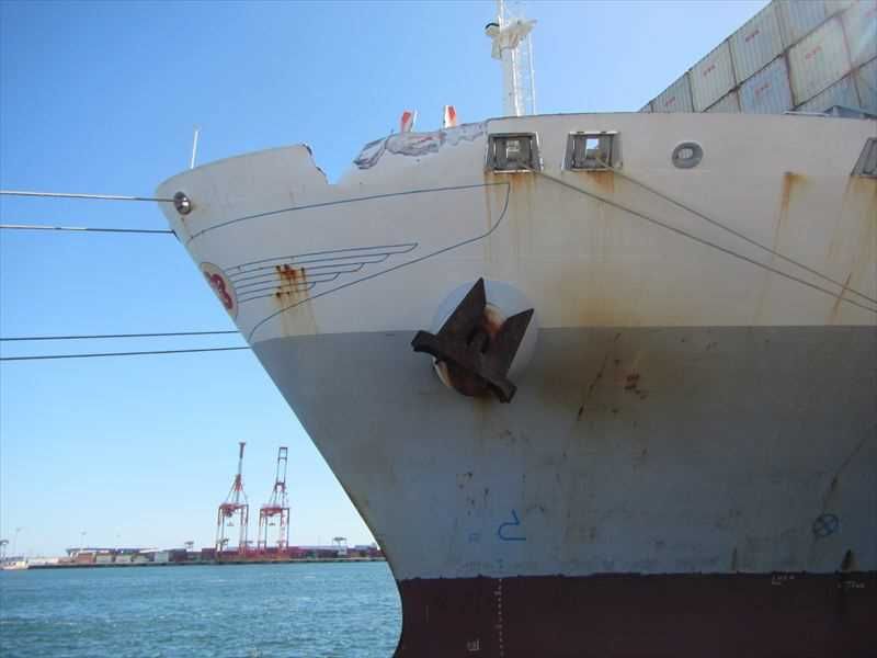
07:30:03      34-59-27.5     136-40-33.8      287        283.9           4.2
07:31:03      34-59-28.5     136-40-28.9      286        284.2           4.0
07:32:03      34-59-29.2     136-40-24.2      281        280.2           3.8
07:33:03      34-59-29.7     136-40-19.9      278        272.4           3.6
07:34:03      34-59-29.8     136-40-15.6      279        267.5           3.2
07:35:03      34-59-29.5     136-40-12.0      281        265.5           2.8
07:36:04      34-59-29.5     136-40-08.9      281        272.4           2.5
07:36:33      34-59-29.6     136-40-07.4      280        272.9           2.1
07:37:04      34-59-29.5     136-40-06.5      279        261.6           1.2
07:37:23      34-59-29.4     136-40-06.3      281        231.2           0.7
07:37:43      34-59-29.2     136-40-06.3      281        179.6           0.5
07:38:04      34-59-29.0     136-40-06.5      280        157.1           0.4
07:38:23      34-59-28.9     136-40-06.2      280        200.8           0.5
07:38:43      34-59-28.7     136-40-06.0      282        235.0           0.9
07:39:04      34-59-28.5     136-40-05.4      284        255.7           1.8
07:39:13      34-59-28.4     136-40-05.0      286        260.9           2.0
07:39:23      34-59-28.4     136-40-04.5      287        269.2           2.3
07:39:33      34-59-28.5     136-40-04.1      287        283.9           2.4
07:39:43      34-59-28.6     136-40-03.6      286        281.9           2.4
07:39:52      34-59-28.7     136-40-03.2      287        272.8           1.9
07:40:04      34-59-28.8     136-40-03.0      288        307.1           1.4
07:40:13      34-59-28.9     136-40-02.8      289        306.6           1.3
07:40:23      34-59-29.1     136-40-02.6      289        312.7           1.4
07:40:33      34-59-29.2     136-40-02.3      288        326.1           1.5

                   Heading           COG              SOG

Figure 1 Changes in Speed over the ground (SOG), Course over the ground (COG), and
           Heading based on AIS records.

                                      - 3 -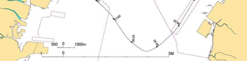
2.1.2 Records of Main Engine Operation
        According to the records of the telegraph logger*4 of the Vessel, the use of the main engine
     between 07:33.0 and 07:39.0 on August 17, 2018, was as shown in Table 2.1-2.

                           Table 2.1-2 Operating condition of Main engine
                          operation time                   Engine order
                               07:33.0          STOP
                               07:36.0          D.SLOW-AS
                                                SLOW-AS
                                                HALF-AS
                                                FULL-AS
                               07:37.0          HALF-AS
                                                STOP
                               07:37.5          D.SLOW-AH
                               07:38.0          SLOW-AH
                                                HALF-AH
                               07.38.5          FULL-AH
                               07:39.0          STOP

 2.1.3 VDR Records of the Vessel
        According to the audio recorded by the Voyage Data Recorder (hereinafter referred to as
     "VDR”)*5 installed in the Vessel, the status of the maneuvering order at the Vessel Bridge
     from around 07:21 to around 07:40 was as shown in Table 2.1-3 below.
        In addition, the information recorded in the VDR concerning the utterances of the master
     of the Vessel (hereinafter referred to as “the Master”), the pilot (hereinafter “the Pilot”) and
     the crewmembers of the Vessel, and the operation of the main engine and rudder are
     provided.

                               Table 2.1-3 Information such as audio (excerpt)
        Time                                             Voice, etc.
     07:21:34       The Pilot:Dead slow ahead.
                    Crewmember:Dead slow ahead.
     07:21:49       Crewmember:Engine dead slow ahead, sir.
     07:22:07       The Master:2, 8, 5.

*4      "Telegraph logger" is a device that automatically records the operation and operation time of an engine
     telegraph (a device that remotely controls the main engine from the bridge).
*5      “Voyage Data Recorder (VDR)” refers to a device that can record a ship’s position, course, speed, radar
     information and other data related to navigation, as well as communications by VHF radio telephone and
     voice communication on the bridge, among others.

                                                      - 4 -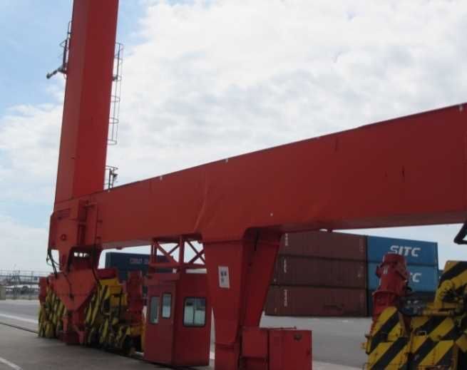
Crewmember:2, 8, 5.
07:22:44   The Pilot:Can you see the bridge mark?
           The Master:Yeah.
07:22:47   The Pilot:End of gantry crane.
07:22:52   The Master:Gantry crane is the last?
07:22:53   The Pilot:Last one .
           The Master:Yeah. Course to the last one.
07:22:55   Crewmember:Yes.
07:23:17   Crewmember:Mark end by, sir.
07:23:19   The Pilot:OK. This degree.
07:23:27   The Master:The ship behind planning berth?
07:23:29   The Pilot:Hmm?
07:23:30   The Master:The ship behind afterward. 60 meters?
           [Voice unclear]
07:24:00   The Pilot:2 bits away.
           The Master:2 bits?
           The Pilot:Yes.
07:24:07   The Master:OK.
07:24:18   The Pilot:Stop engine.
           Crewmember:Stop engine.
07:24:42   Crewmember:Engine stop, sir.
           The Pilot:OK.
07:25:01   The Pilot:Dead slow ahead.
           Crewmember:Dead slow ahead.
07:25:05   The Pilot:[In Japanese to the tug boat] Pull by the dead slow.
           Tug boat:[In Japanese] Roger.
07:25:30   The Pilot:Steady.
           Crewmember:Steady.
07:25:40   Crewmember:Captain, Captain, steady, over.
07:26:45   Crewmember:Course 2, 8, 3.
07:26:47   The Pilot:OK.
07:26:52   The Pilot:Steady.
07:27:04   The Pilot:Stop engine.
           Crewmember:Stop engine.
07:27:22   Crewmember:Engine stop, sir.
           The Pilot:OK.
07:27:34   The Pilot:[to the tug boat] Stop engine.
07:27:36   Tug boat:[In Japanese] Roger.
07:28:12   The Pilot:Dead slow ahead.
           Crewmember:Dead slow ahead.
07:29:35   The Pilot:[In Japanese to the tug boat] I'm going to use the thruster.
07:30:06   The Pilot:Captain, Thruster?
           The Master:Roger. It’s standby.
07:30:12   The Pilot:Dead slow to starboard.
           Crewmember:Pace ease.
           The Master:OK, enough. Enough.

                                        - 5 -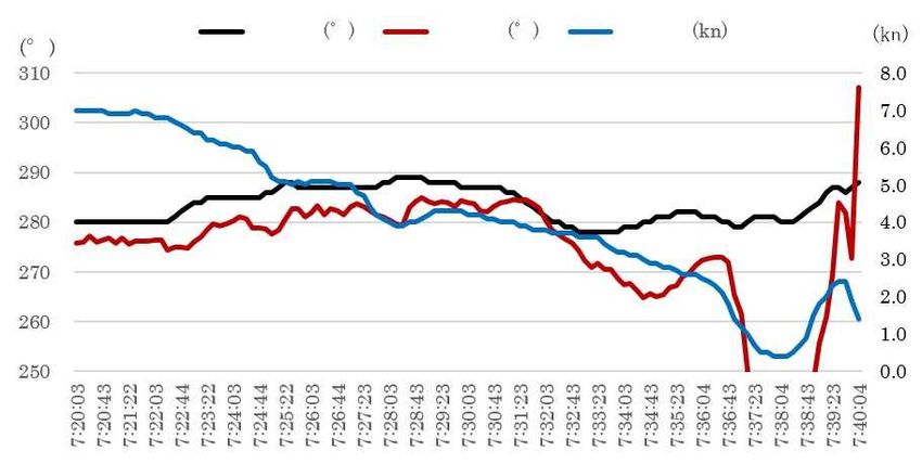
07:30:34       The Pilot:Port 20.
                    Crewmember:Port 20.
     07:30:38       Crewmember:Port 20, sir.
                    The Pilot:OK.
     07:31:28       The Pilot:2, 7, 8.
                    Crewmember:2, 7, 8.
     07:32:44       The Master:Bow thruster*6 ready.
                    Crewmember:Bow thruster ready.
     07:32:46       The Pilot:[In Japanese] Close to the berth.
     07:32:50       The Master:Excuse me sorry.
     07:33:19       The Pilot:Stop engine.
                    Crewmember:Stop engine.
     07:33:32       Crewmember:Engine stop, sir.
     07:33:43       The Pilot:[In Japanese to the tug boat] Move to the starboard side and
                    prepare for pulling.
     07:33:46       Tug boat:[In Japanese] Roger.
     07:34:02       The Pilot:Go a stand.
                    The Master:Yes.
     07:34:25       Crewmember:She was no course, no steady, hard to port.
     07:34:30       The Master:Mid Ships.
                    Crewmember:Mid Ships.
     07:35:26       Crewmember:Steady, 2.6 ahead.
     07:35:59       Crewmember:Now speed 2.5.
     07:36:14       The Pilot:Dead slow astern.
                    Crewmember:Dead slow astern.
     07:36:15       The Master:Too fast, pilot, sir.
     07:36:21       The Master:Too fast. High, high, high, high.
     07:36:24       The Master:Half astern.
                    Crewmember:Half astern.
     07:36:26       The Master:Pull line. Pull line. Tug boat pull line.
     07:36:29       The Master:Full astern.
                    Crewmember:Full astern.
     07:36:32       Crewmember:Full astern, master.
     07:36:38       Crewmember:Full astern.
     07:36:44       The Master:Tug boat pull line fast.
     07:36:54       The Master:Pull line. Pull line. Tug boat pulls.
     07:37:00       The Master:Pull. Pull. Tug boat pulls.
     07:37:03       Crewmember:Still 1.4 ahead.
     07:37:11       The Master:Pull, Tug full.
     07:37:14       Crewmember:Still 1 knot ahead.
     07:37:18       The Master:Stop engine.
                    Crewmember:Stop engine.
     07:37:22       The Master:Starboard full.

*6     "Bow thruster” as Side thruster, refers to a power unit for moving a ship in the side direction, installed
     on the bow.

                                                       - 6 -
07:37:25 Crewmember:Stop.
The Master:Pull Tug Full. Tug, Tug pull. Tug pull.
07:37:34 The Master:Pull.
07:37:40 Unknown:Don’t be shout.
07:37:41 Crewmember:Still go ahead 0.
The Pilot:Dead slow ahead.
07:37:42 The Master:Dead slow ahead, I forgot.
07:37:50 Crewmember:Engine stop.
07:37:51 Crewmember:Full to starboard.
07:37:53 The Master:Dead slow ahead.
Crewmember:Dead slow ahead.
07:37:53 The Master:Pull Tug hard.
07:38:02 The Pilot:Hard starboard.
Crewmember:Hard starboard.
07:38:03 The Master:Half ahead.
Crewmember:Slow ahead.
07:38:06 Unknown:Don’t be shout.
07:38:07 The Pilot:Full ahead.
07:38:08 The Master:Full ahead.
07:38:09 The Pilot:Full ahead.
07:38:10 Crewmember:Full ahead.
07:38:14 The Master:Freeze, Oh, freeze.
07:38:17 The Master:Pull. Tug boat pulls.
07:38:23 The Master:Pull hard. Tug boat pulls hard.
07:38:33 Crewmember:More advance.
07:38:34 The Master:Pull starboard, pull.
07:38:35 The Master:[In Japanese to the tug boat] Pull a little more.
07:38:43 The Master:Full ahead.
Crewmember:Now, Full ahead.
07:38:57 The Master:Pull.
Crewmember:Now, Full ahead.
07:39:00 The Master:Yes.
07:39:02 The Pilot:Hard port, Hard port.
07:39:03 The Master:Oh, ease to hard port.
Crewmember:Ease to hard port.
07:39:09 Crewmember:Hard port.
07:39:21 Crewmember:Clear her bow.
07:39:24 The Master:Mid Ships.
Crewmember:Mid Ships.
07:39:26 The Master:Stop engine.
Crewmember:Stop engine.
07:39:31 The Master:Pull Tug, pull Tug.
07:39:35 Crewmember:Now, Mid Ships.
07:39:37 The Pilot:[To the tug boat] Hard to pull.
- 7 -07:39:39
The Master:Hard Starboard.
Crewmember:Hard Starboard.
07:39:46 Crewmember:Engine stop.
07:39:50 Crewmember:Still hard to starboard.
07:39:50 The Master:Mid Ships.
Crewmember:Mid Ships.
2.1.4 Video and audio recorded in the drive recorder
According to the records of the drive recorders mounted respectively in the two vehicles
parked on No. 26 berth of Kasumigaura Minami Wharf (hereinafter referred to as "the
Berth"; regarding the other berths of Kasumigaura Minami Wharf, the phrase
"Kasumigaura Minami Wharf" is omitted) by the stevedores who worked on the mooring of
the Vessel, etc., the collision situation between the Vessel and the port facility was as follows.
The drive recorders also recorded the audio sounds between the tug boat and the Pilot
communicating by transceiver in Japanese.
The drive recorder mounted on the vehicle located at 34.9917° north latitude and
136.6655° east longitude is referred to as "Recorder A", and that mounted on the vehicle
located at 34.9915° north latitude and 136.6660° east longitude is referred to as "Recorder
B".
(See Figure 2)
Planned berthing position
S1 S3 Recorder B
Recorder A
The gantry crane S2 Unit
The Berth
Direction of shooting with the recorder→
Figure 2 Approximate position of drive recorders
(1) Recorder A
From around 07:39:39, Recorder A recorded that an impact sound began to be heard
with intermittent frictional noise, between the gantry crane*7 (S2 Unit) on the Berth
*7 In this report, "gantry crane" refers to a heavy crane that is set on a gantry on a pier and runs on rails
for the purpose of loading containers.
- 8 -(hereinafter referred to as “GC S2”), and that the bulwark of the Vessel’s fore port part
that contacted the gantry crane and the gantry leg part of GC S2 were moving in front
of the screen. (See Figure 3)
Left: 07:39:37, Right: 07:39:40
Figure 3 Record from Recorder A (excerpt)
(2) Recorder B
Recorder B recorded the impact sound heard from around 07:39:39 for more than 10
seconds, the contact between hull plate of the Vessel’s port side and the Berth, and the
concrete flakes blowing upwards. (See Figure 4)
Left: 07:39:38, Right: 07:39:42
Figure 4 Record from Recorder B (excerpt)
2.1.5 Events Leading to the Accident according to the interview with the Pilot, etc.
According to the statement of the Pilot and the reply by the Master to the questionnaire,
the events leading to the accident were as follows.
- 9 -The Vessel was boarded by the Master and 23 others (18 people from the People's
Republic of China and 5 people from the Republic of the Philippines), it had loaded 18,536.9
tons of container cargo, the Pilot was on board, it had departed from Nagoya Port in Aichi
Prefecture at around 05:30 on August 17, 2018, and it was subsequently bound for the Berth.
Prior to the departure, at around 05:00, the Pilot visited the Vessel which had moored at
a departure berth and exchanged information with the Master in the Vessel's navigation
bridge. The contents of the information exchange were that the Pilot confirmed the
maneuvering performance of the Vessel using the pilot card*8, and then the Pilot explained
to the Master the summary of the pilotage plan, laying out weather information distributed
by a private information company and a pilot information card*9, and then accepted an
agreement from the Master to use one tug boat (3,500 HP) due to the anticipated average
wind speed of less than 10 m/s when departing from Nagoya Port and entering Yokkaichi
Port.
The Master had command over the Vessel maneuvering, a Navigation Officer was
keeping watch, a Deck Cadet was handling the engine telegraph under supervision of a
Navigation Officer on watch, an Able Seaman was steering the wheel in manual operation
and the Pilot was maneuvering the Vessel for the pilotage, the Vessel was navigating
southward from the ordinary route while adjusting the navigation time, restraining the
ship speed, and taking a round route in consideration of the time of the cargo handling.
When the Vessel departed from the East route of Nagoya Port, it was approaching a
domestic cargo vessel which was entering the anchorage, and then the Pilot contacted the
domestic cargo vessel and instructed the Vessel to be maneuvered so as to pass starboard-
to-starboard.
The Master inquired with the Pilot concerning the intention of maneuvering the Vessel
by passing the domestic cargo vessel starboard-to-starboard, and received an explanation
from the Pilot that he was required to pass starboard-to-starboard by the domestic cargo
vessel through radio communication.
At around 07:13, the Vessel entered No. 3 passage in Yokkaichi Port, took the tug line
from the tug boat on the starboard stern, prepared both anchors, and then was taking the
approach for port side head-in toward the Berth seeing port fore, subsequently began to
decrease the ship speed by using the main engine operation and the tug boat.
*8 “Pilot card” refers to the document handed over from a master to a pilot which notes the information of
cargo condition, propulsion unit, maneuvering performance, etc. for a vessel.
*9 “Pilot information card” refers to the document handed over from a pilot to a master which notes the
information of maneuvering methods, methods to use tug boats, etc.
- 10 -The Pilot recognized that at around 07:26, when the ship speed was reduced to
approximately 5 kn (ground speed, the same applies hereafter), the leeway*10 was between
2° and 3° due to northward wind.
While the Vessel was navigating by the course set to 285° in order of dead slow ahead at
around 07:29, since the Vessel was passing northerly in the port in consideration of the
north-west wind, the Pilot thought that the Vessel was going to approach the Berth at a
larger angle.
At around 07:32, the Pilot noticed the Master taking a heading to the bridge mark located
on No.27 berth on the west of the Berth, and then transmitted to steer to port and to change
the course to 278°.
The Pilot transmitted an instruction to stop the main engine at around 07:33, since the
ship speed became approximately 3 kn, and then commanded the tug boat by the
transceiver to move to the starboard side and to prepare to pull toward the 3 o’clock
direction. Subsequently, the Pilot moved from the navigation bridge interior to the port
wing with the Master.
The Master remembered seeing that the ship speed was indicated as 3.9 kn on the display
screen of the Electronic Chart Display and Information System*11 (hereinafter referred to
as “ECDIS”) before leaving the navigation bridge interior.
The Pilot recognized that the Vessel body was sweeping away from starboard to port, the
Berth side, and then thought of using the bow thruster at full to starboard and tried to
swing the bow to starboard. The Pilot transmitted to the Master that after a while, he
would reduce the ship speed by using the astern engine. The Pilot continued to use the
bow thruster at full to starboard because the Vessel had been sweeping away heavily more
than he had expected, and subsequently he instructed the tug boat to tighten the line taken
at the stern toward the 3 o’clock by transceiver.
When the Master had been transferring the Pilot’s instructions from the port wing, he
noticed sudden changes of wind direction and wind speed, and then measured by eye the
separation distance of approximately 90 meters between the Vessel and a car carrier of
length approximately 118 meters which was moored for starboard side head-out with her
*10 “Leeway” refers to the situation in which a vessel has received the wind in navigation while being pressed
downwind, so that the bow direction does not match the moving direction of the vessel, and moves in a
skewed manner. It indicates the degree of the lateral flow of the vessel.
*11 “Electronic Chart Display and Information System (ECDIS)” refers to a device that can display a ship’s
own position on an official electronic chart (Electronic Navigational Chart or Raster Navigational Chart)
that meets the standards of the International Hydrographic Organization (IHO), as well as displaying radar,
scheduled passages and other information in combination, and also has the function of transmitting alerts
when approaching shallows and other hazards.
- 11 -port side to No. 25 berth (hereinafter referred to as “the Moored Vessel”), but he did not
discuss these circumstances with the Pilot.
The Pilot thought that if the ship speed was not maintained to a certain extent, the Vessel
would be swept further and further away to port side. Therefore, the Pilot thought that if
the Vessel increased astern thrust after her stern passed the Moored Vessel and used the
main engine by half astern, the Vessel could proceed in front of the Berth and could stop,
thereby the bow of the Vessel would swing to the starboard side by the characteristics of a
right-handed rotation single screw vessel*12 and would be allocated a position in parallel to
the Berth; however the Pilot did not explain his thoughts to the Master.
At around 07:36, the ship speed became approximately 2.5 kn, and then the Pilot
transmitted to the Master to use the main engine to dead slow astern and also continued
to use the bow thruster at full to starboard, and subsequently requested the tug boat to pull
to the 3 o'clock direction at dead slow. At that time, the Master asserted to the Pilot
repeatedly that the ship speed was too high.
Although the Master had been transmitted by the Pilot that he would take the main
engine motion from dead slow astern to slow astern, the Master felt that the speed of the
Vessel was too high, had a premonition of failure that the Vessel would fail to accomplish
berthing maneuvering, and therefore it seemed to the Master that the Vessel was swept
away toward the Moored Vessel by a pressurized flow of wind. Therefore the Master
asserted to the Pilot that the Pilot’s maneuvering instruction was insufficient, took
command to take half astern and full astern himself, and got the Vessel to decelerate
immediately, and then urged the Pilot repeatedly to pull by the tug boat to the starboard
side with full power.
Since the Master no longer accepted the Pilot's maneuvering instructions, the Pilot
decided to follow the Master's maneuvering commands and transmitted to the tug boat by
the transceiver to pull the Vessel’s stern to the starboard side with full power, the Pilot
recognized that the Vessel had stopped her forward movement and was sweeping away
heavily to port side.
Since the Vessel was sweeping away and furthermore was approaching the Moored Vessel,
the Master took command and set the steering to hard port, used the main engine and
increased the revolution of the main engine by full ahead, and commanded the tug boat to
*12 “Right-handed rotation single screw vessel” refers to a ship that has one propulsion shaft that rotates
when driven by the main engine, and whose propellers turn clockwise when viewed from her stern, and has
the characteristic that the stern swings to left and the bow swings to right when astern is used (the propeller
is reversed).
- 12 -pull the Vessel’s starboard stern to the starboard side with full power.
The Master accepted the report that the Vessel’s stern had already passed the Moored
Vessel, and then the Master immediately took command, set the steering to mid-ships,
stopped the main engine, and then set the steering to hard starboard.
However, at around 07:39, the port fore part of the Vessel collided with GC S2 on the
Berth, and then continued moving forward while contacting with GC S2, and thereby the
other two gantry cranes, which were not in operation, were pushed and were moved
together by GC S2. In addition, the port fore side plate of the Vessel collided with the
upper edge of the Berth.
At around 07:48, the Vessel sent the first mooring line to the Berth and completed the
mooring works at around 08:24.
The date and time of occurrence of the accident were at around 07:39:39 on August 17, 2018,
and the location was approximately 149° true bearing, 480 meters from Yokkaichi Port
Management Association Kasumigaura No.1 range light (front light)
(See Annex Figure 1 Navigation path and Annex Figure 2 Navigation path in Yokkaichi
Port)
2.2 Injuries to Persons
According to the statement of the Pilot, there were no fatalities or injuries on the Vessel.
2.3 Damage to Vessel
According to the reply to the questionnaires by the Pilot and Company A, these were as
follows:
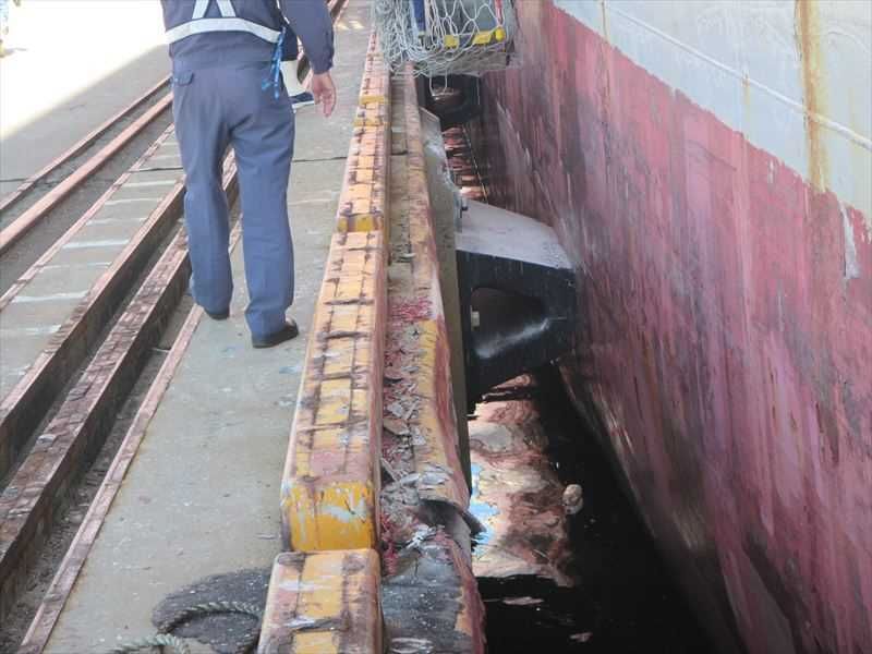
(1) The port bulwark plate was cut and buckled, and the remote control stand of the
mooring equipment was deformed on the forecastle deck
(2) The port fore part of the shell plate was dented.
(See Figure 5 and 6)
- 13 -Figure 5 State of damage to the Vessel (Bulwark on the port fore part)
Figure 6 State of damage to the Vessel (Port fore part shell plate)
2.4 Damage to Other Facilities
According to the statements and the reply of the questionnaires by the person in charge of
the Yokkaichi Port Authority (hereinafter referred to as the “Port Authority”), and the person
in charge of the Yokkaichi City Container Terminal Co., Ltd. (hereinafter referred to as the
“Facility Management Company”) which was commissioned to operate the Container Terminal
of Yokkaichi Port, these were as follows. (See Figures 7-10)
- 14 -2.4.1 Berth
The fenders’ body was cracked, etc., and concrete parts such as the upper surface of the
Berth and the pedestal part of the fenders, were damaged in the form of delamination, etc.,
and the corner metallic fittings at the front edge, etc. of the Berth were bent.
2.4.2 Gantry cranes
The gantry cranes were in the order of GC S2, Unit S3 and Unit S1 from the east side of
the Berth, and were not in operation but were on standby condition. They were all moved
due to the accident. The Unit 3 was damaged at the traveling motor, and the gantry leg
part structure of Unit S3 was deformed. GC S2 was derailed and the traveling equipment
was bent, was broken, etc., and the gantry leg part structure of GC S2 was deformed,
furthermore a part of fixing component of traveling rail was damaged, respectively, and
thereby GC S2 and Unit S3 were caused to be inoperable. Still, Unit S1 was not damaged.
The collision part of GC S2 was the northeast corner of the gantry leg, with a horizontal
distance of approximately 2 meters from the front of the fender installed at the Berth front
edge and a height of approximately 10 meters from the surface of the Berth.
Figure 7 Damage to the quay
- 15 -See Figure9①
See Figure9②
See Figure 10①
See Figure 10②
GC S2, Unit S3 and Unit S1 from the front of the photo
Figure 8 Damage to gantry cranes
① ②
Northeast corner gantry leg part (Impact mark) Southern leg beam (Deformation)
Figure 9 Damage 1 to GC S2
① ②
Northwest corner gantry leg part (Derailment) GC S2 and Unit S3
(Damage of traveling devices)
Figure 10 Damage 2 to GC S2
- 16 -2.5 Crewmember Information
(1) Gender, Age, Certificate of Competence
The Master: Male 60 years old, Nationality: Republic of Singapore
Endorsement attesting the recognition of certificate under STCW regulation I/10:
Master (issued by the People's Republic of China)
Date of Issue: August 24, 2017
(Valid until June 8, 2022)
The Pilot: Male 58 years old, Nationality: Japanese
Ise-Mikawa Wan Pilot District First Class Pilot’s License
Date of Issue: January 13, 2018
Date of Revalidation: January 13, 2018
Date of Expiry: January 12, 2022
(2) Seagoing Experience, etc.
According to the statement by the Pilot, the replies by the Pilot and the Master of the
questionnaires of response, there were as follows.
① The Master
In June 1992, he assumed the role of master and worked at sea for about three years.
After working ashore, he resumed boarding on container vessels of a similar type as
the Vessel in September 2017, and then he had been on board the Vessel since June
2018.
At the time of the accident, there was no problem with his health.
② The Pilot
He joined a shipping company in 1983, had taken experience as a marine technician
while he had been working at sea and on land alternately. He had taken experience
as a captain for approximately two and a half years and was working mainly on car
carriers. He became a pilot of Ise-Mikawa Bay Pilot District in February 2017, and
has been engaged in pilotage work for approximately one and a half years.
At the time of the accident, there was no problem with his health.
2.6 Vessel Information
2.6.1 Principal of the vessels
IMO No.: 9445538
Port of registry: Hong Kong Special Administrative Region of the
People's Republic of China
- 17 -Owner: NEWCONTAINER NO 102 (MARSHALL ISLANDS)
SHIPPING INC (Republic of the Marshall Islands)
Operator: ORIENT OVERSEAS CONTAINER LINE LIMITED (Hong
Kong Special Administrative Region of the People's
Republic of China) (hereinafter referred to as “Company A”)
Management Company Company A
Classification Society: Nippon Kaiji Kyokai
Gross tonnage: 40,168 tons
L x B x D: 260.05m x 32.25m x 19.30m
Hull material: Steel
Engine: Diesel engine x 1
Output: 36,560kW
Propulsion: 6-blade fixed pitch propeller x 1
Date of construction: July, 2009
(See Figure 11)
Figure 11 The Vessel
2.6.2 Load conditions
According to the replies to the questionnaires from the Master and Company A, the Vessel
had a capacity of 4,578 TEU, and at the time of the accident, 18,536.9 tons of containers
were loaded, and the draft was approximately 8.70 meters at fore and approximately 9.30
meters by the at stern.
2.6.3 Navigation equipment, etc.
According to the replies of the questionnaires from the Master and Company A, the Vessel
was equipped with two radars, ECDIS, etc., which were in use at the time of the accident.
2.6.4 Information about the Maneuverability
According to the maneuverability characteristics table of the Vessel, her maneuverability
- 18 -was as follows.
(1) Main engine revolutions and speed
Main engine’s Speed Speed
Speed classification rotations per minute Loaded condition Ballast condition
(rpm) (kn) (kn)
Navigation full ahead 100.4 23.85 25.17
Full ahead 70.0 16.8 18.5
Half ahead 45.0 10.4 11.2
Slow ahead 35.0 7.0 7.6
Dead slow ahead 29.0 6.2 6.7
(2) Time and distance needed until stopping at speed full astern
Loaded condition Ballast condition
State when astern
Time Distance Time Distance
engine order is issued
(seconds) (M) (seconds) (M)
Navigation full ahead 664 1.975 427 1.364
Half ahead 414 0.679 270 0.478
(3) Effect of bow thruster
Direction Turning angular velocity at 0 kn Speed of ineffectiveness
To starboard 16.8 deg/min
5kn
To port 13.9 deg/min
2.6.5 Other Relevant Vessel Information
(1) According to the Pilot card, the output of the bow thruster was 1,600 kW.
(2) According to the statements by the Pilot and the Master's replies to the
questionnaires, there were no malfunctions or failures in the hull, engine, or
equipment of the Vessel at the time of the accident.
2.6.6 Information about Tug boat
According to the description of Register of ships in Japan, the engine output of the tug
boat which was used at the time of the Vessel’s berthing, was 3,500 HP (2,574 kW).
2.7 Information on Bridge Organization
2.7.1 Situation concerning communication
According to the statement by the Pilot, voice information recorded on the VDR, and the
voice recordings of Recorder A and Recorder B, the commanding orders and the instructions,
communication and their conversations among the Master, the Crewmember and the Pilot
were conducted in English, and the communication by transceiver between the Pilot and
the tug boat was conducted in Japanese.
- 19 -2.7.2 Information on information exchange
According to the statement by the Pilot, the replies from the Ise-Mikawawan Pilots'
Association (hereafter referred to as "the Pilots' Association") and the Master to the
questionnaires, there were as follows.
(1) Prior to departure from Nagoya Port, the Master and the Pilot signed in a pilot card,
a pilot information card and a checklist for communication between the Master and
the Pilot, and then confirmed the pilotage plan mutually.
(2) The pilot information card presented in item (1) described turning directions of the
Vessel, the number of tug boats used when leaving the berth of Nagoya Port and
arriving at the Berth and the standard route between ports, etc. However, there was
no description of the target, heading, etc. at the time of maneuvering for approaching
the Berth.
(3) After the Vessel had avoided a domestic cargo vessel from Nagoya Port to the Berth,
the Master inquired with the Pilot as to the Pilot’s intention for maneuvering to avoid
that vessel and received a response from the Pilot.
(4) The Master and the Pilot exchanged information concerning the mooring place at
approximately 07:22; however after that time, they did not exchange information with
each other concerning whether the Vessel would accept pressurized flows.
(5) When the crewmembers received maneuvering commands from the Master and the
Pilot, the crewmembers repeated these orders and then reported the response actions
according to the commands. However, the crewmembers had hardly reported
anything concerning leeway increases, change of wind force, etc.
2.7.3 Information on the situation surrounding the Vessel and decisions on maneuvering
According to the statement of the Pilot, the replies from the Pilots' Association and the
Master to the questionnaires, there were as follows.
(1) The Master
① When confirming the pilotage plan, the Master did not receive detailed
explanations concerning the measures of approaching the Berth, such as the course,
or the ship speed, etc. at the time of berthing from the Pilot; therefore the Master
thought that it was necessary to observe the Pilot's behavior carefully.
② At around the time of the Vessel being in parallel with the Moored Vessel, the
Master observed the situation that the Vessel was sweeping away by wind blowing
from the sea to the Berth and was being blown to the Mooring Vessel immediately,
- 20 -and then he seemed to feel that the ship speed was more than 4 kn and was too much
faster than standard berthing maneuvering.
③ The Master noticed that the deceleration being conducted by the Pilot was not
sufficient to approach the Berth safely, and then he intervened immediately and took
command of maneuvering the Vessel himself due to aborting her movement
completely, and subsequently ordered full astern and thereby the Vessel was
decelerated immediately.
(2) The Pilot
① The Pilot thought that he had good communication with the Master due to the
Master always standing to his right side and often talking about avoiding the
domestic cargo vessel, etc. when leaving Nagoya Port.
② The Pilot was navigating the Vessel on a route further north than the ordinary
route in consideration of the influence of winds, and then thought the Vessel would
be approaching the Berth at a large angle, and transmitted his instruction that her
course was set at 278° due to the separation distance being larger from Kasumigaura
Minami Wharf.
③ When transmitting the course of 278°, the Pilot thought that he was recognized
that the course had been accepted by the Master due to the Master raising no
objections.
④ The Pilot thought that the wind was intensifying and the Vessel was swept away
heavily to port side, however the Vessel was delaying a little to reduce the ship speed
and continue to move forward, and thereby it would be possible to be berthing at the
Berth by using half astern and controlling the forward movement.
2.8 Weather and Sea Conditions
2.8.1 Meteorological observations and Tide
(1) Meteorological observations
According to meteorological observations at the Yokkaichi Special Regional
Meteorological Observation Station, which is located approximately 9.7 km west-
southwest of the accident site, there were as follows.
Average wind speed Maximum instantaneous wind speed
Time
Wind speed (m/s) Wind direction Wind speed (m/s) Wind direction
07:00 2.2 North 7.3 North
07:10 4.3 NNW 9.8 North
07:20 3.8 NNW 8.7 North
07:30 4.5 NNW 8.7 North
07:40 4.2 NNW 8.0 North
- 21 -07:50 4.8 NNW 9.6 North
The weather was fine and visibility was 20 km.
(2) Observations of Port Authority
The observation data of the anemometer installed near the accident site by the Port
Authority on the day of the accident were as follows.
Average wind speed Maximum instantaneous wind speed
Time
Wind speed (m/s) Wind direction Wind speed (m/s) Wind direction
07:10 8.0 NW 15.5 NW
07:20 8.8 NW 13.3 NW
07:25 9.6 NW 13.3 NW
07:26 9.5 NW 14.5 NW
07:27 9.8 NW 17.1 NW
07:28 9.8 NW 17.1 NW
07:29 10.0 NW 17.1 NW
07:30 10.0 NW 17.1 NW
07:31 10.0 NW 17.1 NW
07:32 10.0 NW 17.1 NW
07:33 10.0 NW 17.1 NW
07:34 10.1 NNW 17.1 NW
07:35 10.1 NW 17.1 NW
07:36 10.0 NNW 17.1 NW
07:37 9.5 NW 15.4 NW
07:38 9.4 NW 15.4 NW
07:39 9.2 NW 13.9 NW
07:40 9.2 NW 13.9 NW
(3) Tide
According to the tide table published by Japan Coast Guard, the tide was at the
middle of rising and the height was approximately 1.6 m at Yokkaichi Port.
2.8.2 Observation by crewmembers, etc.
At the time of the accident, it was as follows.
(1) According to the navigation logbook of the Vessel, wind from northwest and wind
force 5 were written in the column from 07 o'clock to 08 o'clock.
(2) According to the reply from the Pilot, the weather was fine, wind direction was
northwest to north-northwest, wind speed was 8 m/s to 12.5 m/s, and the visibility was
10 km.
- 22 -2.8.3 Announcement of Warnings and Advisories
At the time of the accident, Warnings and Advisories had not been issued.
2.9 Characteristics of the Area Information on Bridge Organization
2.9.1 Information on pilotage
(1) Compulsory pilotage area and object vessels
According to Article 35 of the Pilotage Law (Act No.121 of 1949) and Article 5 of the
Government ordinance pursuant to the Pilotage Law (Government ordinance No.354
of 1964), the Ise-Mikawa Bay district including the site of the accident is designated
as a compulsory pilotage area, and it is stipulated that a master of a vessel with a
gross tonnage of 10,000 tons or more must have a pilot on board.
(2) Standards for maneuvering and mooring
According to the Standards for maneuvering and mooring stipulated by the Pilots’
Association, the main standards applied to the Vessel when berthing at Yokkaichi Port
were as follows. The standard of wind speed less than 10m/s was applied by the
exchange of information between the Master and the Pilot at the time of the departure
from Nagoya port.
a The minimum distance between two vessels moored at a similar berth was 35
meters in principle.
b If wind speed was 15 m/s or more, the pilotage services were suspended.
c If wind speed was 10m/s or more, the number and size of tug boats used for
pilotage was determined according to the situation at that time.
d When wind speed was less than 10 m/s, the standard for using tug boats was to
use two tug boats with an output of 3,000 HP (2,237 kW).
e If a bow thruster with a nominal horsepower of 1,600 HP (1,193 kW) was equipped,
one tug boat might be reduced.
(3) Reference materials of Standards for maneuvering and mooring
According to the Pilots’ Association's reference materials, it was recommended that
a course be set at 285° as the fore target to the intersection part of No. 27 berth and
No. 70 berth when approaching for port side head-in toward the Berth. Also,
navigators should be careful of northerly winds and take a course with a sufficient
margin against wind which had an influence sweeping away toward the Berth, and
take also a course of 290° as the fore target aiming at the joint part between No. 70
berth and No. 71 berth in consideration of sweeping away to leftward was described,
and the Pilot had already been aware of these things.
- 23 -2.9.2 The Berth
According to the statements and the replies of the persons in charge of the Port Authority
and the Facility Operation Company, and the Sailing Directions for South & East Coasts of
Honshu, published by the Japan Coast Guard, there were as follows.
The Berth was located in the northern part of Kasumigaura Minami Wharf in the
northern part of Yokkaichi Port. The berth normal line*13 direction was approximately
295°, the length was 300 meters, and the depth of the front water area was approximately
13.2 m.
The Rail grooves were provided at 2 meters and 18 meters from the front edge on the
upper surface of the Berth, so that the traveling devices of the gantry cranes were able to
move on them.
There are two gantry cranes on the Berth and one gantry crane on the adjacent No. 27
berth. Furthermore, there were three gantry cranes on Kasumigaura Kita Wharf No. 80
berth facing the Berth. All of the gantry cranes were operated as core facilities of Yokkaichi
container terminal.
2.9.3 Mooring plan for the Berth
According to the statements and the replies by the person in charge of the Facility
Operation Company to the questionnaires, there were as follows.
If there was a container vessel that was going to a berth on the container terminal, the
Facility Operation Company would prepare a “Ship Mooring Plan” which was indicated
using mooring bits, the position of the navigation bridge at the time of berthing, and
allocations of the gantry cranes, etc., and then sent them to the shipping agent, stevedore,
etc. in advance.
When the flare (overhang toward the outer side of shell plating) of the fore part and the
stern part of a container vessel oscillated horizontally, the upper part of the vessel body
would push out over the berth. Therefore, the Facility Operation Company assigned gantry
cranes that avoid fore and stern structures in the berthing. The gantry cranes were
assigned around the center of the body in the “Ship Mooring Plan” for the Vessel.
At the time of the accident, the gantry cranes were arranged in the order of the Berth
near the bits of 264-267 on the Berth, in order of GC S2, Unit S3 and Unit S1 from east.
The mooring lines of the Vessel were planned to use the bit of 271 concerning the fore side
and the bit of 260 concerning the stern side, and stern side mooring line of the Moored Vessel
*13 "Berth normal line" refers to an extension line of the plane of the berth where the vessel is contact-moored.
- 24 -was planned to use the bit of 257. The installation interval of each bit was 30 meters.
(Refer to Attached Figure 2 Navigation path in Yokkaichi Port)
2.9.4 Status of container handling since the accident occurred
According to the statements and the replies by the persons in charge of the Port Authority
and the Facility Operation Company, there were as follows.
After the accident, Unit S1 was able to operate only out of three gantry cranes installed
on Kasumigaura Minami Wharf. As the large-sized container vessels were going to have
to handle container cargo at Kasumigaura-Kita Wharf No. 80 berth, the container storage
capacity of the wharf came to exceed the wharf’s performance; therefore the container
terminal required the works to transfer unloaded containers by land transportation to the
Minami Wharf.
2.10 Information on Safety Management of the Vessel
Company A's safety management manual described the responsibilities of the masters and
the watch officers when a pilot is on board as follows.
(1) The presence of the pilot on the navigation bridge does not relieve the master or officers
on watch of their responsibilities for the safe navigation of the vessel.
(2) The master and officers on watch should fully understand the pilot’s intentions.
(3) Upon a pilot boarding, the master should immediately discuss the Pilotage Plan,
(Anchoring / Mooring / Unmooring / Berthing / Unberthing etc.), as applicable, and
furnish a pilot with the “Pilot Card”.
(4) The master, or in his absence, officers on watch, must be prepared to take action to
supersede the pilot if it is thought that the pilot’s actions may endanger the vessel.
However, such action demands careful judgement and shall be made in ample time to
ensure that the safety of the vessel is maintained.
2.11 Other References
2.11.1 Occurrence status of collision with gantry cranes by Container vessel
In a report on the investigation of marine accidents, etc. from October 2008 to December
2019, from which the Japan Transport Safety Board was established, there were 8 accidents
involving gantry cranes by container vessels (5 cases in berthing, 3 cases in unberthing).
Looking at the causes of these accidents, there were 7 cases in which the attitude of a
vessel body could not be controlled, and 1 case in which did not reach the objective berth
due to wind pressure and collided with the berth.
- 25 -For accidents where the attitude of a vessel body could not be controlled in front of the
mooring place, since the ship speed was controlled, the impact at the time of the collision
was relatively small and the damage to the container cranes was relatively slight.
However, in the one case in which the vessel could not reach the planed objective berth due
to sweeping away by wind, the vessel moved too far forward near the planed objective berth
and collided with the gantry crane because the attitude of her body was not able to be
controlled. Therefore the impact at the time of the collision was large, and subsequently
the gantry crane was derailed, was not able to operate, and thereby caused serious damage.
(Refer to Annex Table 1 List of Gantry Crane Collisions by Container vessels)
2.11.2 Standard berthing maneuver
According to literature*14, it is described as follows.
Maneuvering of right-handed, 1 shaft,-1 rudder vessel at berthing is generally carried
out as follows.
(1) Berthing to moor port head-in (Small angle approach, Fig. 6.31)
In case of approaching the berth at a small angle,
the maneuvering of vessel will be carried out according Use tags
to the following procedure. in some situations
① For a vessel of approximately 10,000 gross tons,
the approach angle is 15° to 20° with respect to the
berth normal, and she proceeds to the planned berth
with small inertia toward the destination.
The separation distance from the berth when the
vessel stops in the front of the planned berth can be
approximately 1 to 1.5 times the width of the vessel. Fig. 6.31
Small angle approach
For a vessel over 50,000 gross tons, the approach
angle is generally 10 to 15 degrees, and the separation distance from the berth can
be generally twice the width of the vessel.
② Below (omitted)
2.11.3 Ship speed control for approaching and berthing
According to literature*15, the control of approaching ship speed at berthing is described
*14 Literature: "Basics of Ships Maneuvering (Second Edition)" written by HASHIMOTO Susumu, YABUKI
Hideo and OKAZAKI Tadatane, Kaibundo-Shuppan Co., Ltd. (issued March 15, 2012)
*15 Literature: "Theory and Practice of Ships Maneuvering" by INOUE Kinzo, Seizando-Syoten Co., Ltd.
- 26 -as follows.
1.3 Guideline for ship speed reduction control
When approaching a berth, most pilots are aware that, in the ship speed reduction
plan, the safety margin is included in the range from 0.3 to 0.6 under the braking force
of Dead Slow Astern, on any vessel type eg. VLCC, PCC, Container vessel. The Pilots'
estimations of the safety margin appear to include considerations for "Keeping the
vessel far from large swinging."
While utilizing the importance of this know-how and taking safety margins into
account and response, it would be possible to make adjustments to the ship speed of
forward movement based on always making firm decisions in approach maneuvering.
The Practical guidelines for ship speed reduction are shown in Fig. 3.1.21.
Fig. 3.1.21 shows the guidelines for the ship speed reduction for approach
maneuvering of each type of vessel.
■ Available speed area
The speed area below the curve indicating the condition that the safety margin
becomes zero when braking is used to Dead Slow Astern is basically defined as the
available speed area. All of the pilots' speed reduction plans were within this range.
This is a pilot's know-how cultivated from empirical judgment that it is desirable to
control the ship speed of forward movement within this range so as not to allow the
ship to sway to a large extent.
■ Recommendable speed area
In the available speed area, two-thirds of the total pilots are also aware of the
safety margin from 0.3 to 0.6. The fact that many pilots concentrate on this area
probably suggests that this speed area is the most practical, based on the pilots’ long
experience. In that sense, here, this speed area is referred to as a recommendable
speed area. However, in the available speed area, the safety margin is in the range
of 0 to 0.3 based on the braking force of Dead Slow Astern. Some pilots responded
that they set the ship speed reduction plan in a somewhat bold manner, with a speed
area where the safety margin is lower than 0.6 based on the braking force of Dead
Slow Astern, while other pilots answered that they set the speed reduction plan quite
carefully. These areas sandwiching the recommendable speed area are positioned in
"available" but not "recommendable".
(omitted below)
(issued March 8, 2011)
- 27 -Speed (kn)
Distance to Berth (m)
(Container vessel, PCC, LNG carrier)
Fig. 3.1.21
3 ANALYSIS
3.1 Situation of the Accident Occurrence
3.1.1 Course of the Events
According to 2.1, it is considered probable as follows.
(1) At around 07:22, the Pilot and the Master exchanged information concerning the
Berth, and navigated to the course of 285° while the Vessel decelerated.
(2) At around 07:32, the Vessel changed the course to 278°. After a while the leeway
exceeded 10° from around 07:34:03 to around 07:35:53, and then the Vessel was swept
away heavily toward the port side, No. 25 berth and the Moored Vessel.
(3) At around 07:36:04, the Vessel was approximately 260 meters from the Berth and
the ship speed was approximately 2.5 kn, and then at around 07:36:14, she used astern
engine, but shortly thereafter, the Vessel decelerated immediately by using full astern .
(4) At around 07:37:41, the Vessel lost forward movement near the Moored Vessel, and
then it was forced to sweep away to port side and furthermore approached the Moored
Vessel.
(5) The Vessel was quite near the Mooring Vessel, and used the main engine by full
ahead at around 07:38. Thereafter, since the Vessel was able to pass the Moored
Vessel, the main engine was stopped; however, at around 07:39:39, the port fore part
of the Vessel collided with GC S2.
3.1.2 Date, time and the location of this accident
- 28 -(1) Time and date of the accident
According to 2.1.3 and 2.1.4, it is considered highly probable that the occurrence date
and time of the accident was on August 17, 2018, at around 07:39:39, when the impact
sound was recorded on both the VDR and the drive recorders.
(2) Accident location
According to 2.1, it is considered highly probable that the location of the accident was
around 149°, 480 meters from the Yokkaichi Port Management Association
Kasumigaura No.1 range light (front light) where the northeastern leg part of GC S2
was located.
3.1.3 Situation about the collision
According to 2.1.1, 2.9.2, 3.1.1 and 3.1.2, it is considered highly probable that the heading
of the Vessel at the time of the collision was approximately 286°, the ship speed was
approximately 2.4 kn, and the intersection angle between the centerline and the face line
of the berth was approximately 9°.
3.1.4 Information of casualties or injuries
According to 2.2, it is considered probable that there were no casualties or injuries in this
accident.
3.1.5 Damage to the vessel and other facilities
According to 2.3 and 2.4, it is considered highly probable that these were as follows.
(1) The Vessel
① Breakage of the port bulwark of the fore castle deck with cutting, deformed to the
remote control stand of the mooring device
② Denting of her shell plate on her port fore part
(2) The Berth
The fenders’ body was cracked, etc, concrete parts such as the upper surface of the
Berth and the pedestal of the fenders were damaged in the form of exfoliation, etc. and
the metal fittings at the front edge of the Berth were damaged.
(3) The gantry cranes
All of the gantry cranes on the Berth were moved, the traveling device of Unit S3
was the damaged and the leg part structure was cracked, deformed, etc. GC S2 was
derailed and the traveling device was bent, was broken, etc., this leg part structure
was deformed, and furthermore a part of fixing component of traveling rail was
damaged, etc. As a result, GC S2 and Unit S3 were in an inoperable condition. Still,
- 29 -there was no damage to Unit S1.
3.2 Causal Factors of the Accident
3.2.1 The situation of the crewmembers, etc.
According to 2.5, the situation of the crewmembers, etc. were as follows.
(1) The Master
The Master possessed legally valid certificates of competence.
It is considered probable that he was in good health at the time of the accident.
(2) The Pilot
The Pilot possessed a legally valid certificate of competence as a pilot.
It is probable that he was in good health at the time of the accident.
3.2.2 Situation about the Vessels
According to 2.6.5, at the time of the accident, it is considered probable that there were
no malfunctions or failures in the hulls, engines and equipment of the Vessel.
3.2.3 Information on the weather and sea conditions
According to 2.8, the weather and sea conditions were as follows.
(1) It is considered probable that, at the time of the accident, the weather was fine, a
west-southwest wind was blowing at force 3, the visibility was 5 M or more, waves
with a height of approximately 0.3 meters were coming from the south, and the tide
was at the end of rising.
(2) At around the berth, a northwest wind with a maximum instantaneous wind speed
of 17.1 m/s was observed from 07:27 to 07:36, because winds were strengthening
during that time, and then at 07:34 and 07:35, the average wind speed was 10.1 m/s,
and it is considered highly probable that winds were particularly strong at around
07:34.
3.2.4 Analysis on mooring plan
According to 2.1, 2.9.1 to 2.9.3 and 2.11, it is considered probable that these were as
follows.
(1) The mooring interval between the Vessel and the Mooring Vessel was about 60
meters or more, which satisfies the Standards for maneuvering and mooring of the
Pilots’ Association.
- 30 -You can also read