SOLAR UNDER STORM SELECT BEST PRACTICES FOR RESILIENT GROUND-MOUNT PV SYSTEMS WITH HURRICANE EXPOSURE - Rocky Mountain Institute
←
→
Page content transcription
If your browser does not render page correctly, please read the page content below
MOUN
      KY

             TA
ROC

  IN           IN
       STIT UTE

SOLAR UNDER STORM
SELECT BEST PRACTICES FOR RESILIENT GROUND-MOUNT
PV SYSTEMS WITH HURRICANE EXPOSURE
BY CHRISTOPHER BURGESS AND JOSEPH GOODMAN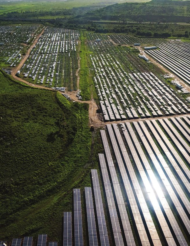
“Fortunately, our island was not impacted last
fall by the hurricanes. However, we are planning
to add a considerable amount of solar PV to our
power system over the next few years and we
want to know how we can ensure the survival of
these new assets”

—Kendall Lee, Managing Director, Montserrat Utilities Limited
AUTHORS
LEAD AUTHORS                                        DISCLAIMER
Christopher Burgess and Joseph Goodman              Rocky Mountain Institute does not endorse any
                                                    products mentioned in this report and shall not be
* Authors listed alphabetically. All authors from   held liable for any damages, including consequential
Rocky Mountain Institute unless otherwise noted.    damages, of any kind that may result from use of the
                                                    information in this report, or any of the product or
                                                    services described therein.
CONTRIBUTING AUTHORS
Kareem Dabbagh
Marc Lopata, Solar Island Energy
Dana Miller, Solar Island Energy
Chris Needham, FCX Solar
Frank Oudheusden, FCX Solar

The report authors thank representatives from the
US National Renewable Energy Laboratory for their
contributions to this document.

CONTACTS
Christopher Burgess, cburgess@rmi.org
Joseph Goodman, jgoodman@rmi.org

EDITORIAL/DESIGN
Editorial Director: Cindie Baker
Editor: Laurie Guevara-Stone
Creative Director: Romy Purshouse
Design: Kaitlin Wutschel

Images courtesy of iStock unless otherwise noted.

COVER PHOTO
Photo by Jocelyn Augustino - Oct 10, 2017
Location: St. Thomas, US Virgin Islands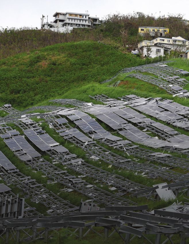
ABOUT US

         MOUN
      KY
             TA
ROC

               IN

  IN
       STIT UTE

ABOUT ROCKY MOUNTAIN INSTITUTE
Rocky Mountain Institute (RMI)—an independent nonprofit founded in 1982—transforms global energy use to
create a clean, prosperous, and secure low-carbon future. It engages businesses, communities, institutions, and
entrepreneurs to accelerate the adoption of market-based solutions that cost-effectively shift from fossil fuels to
efficiency and renewables. RMI has offices in Basalt and Boulder, Colorado; New York City; Washington, D.C.;
and Beijing.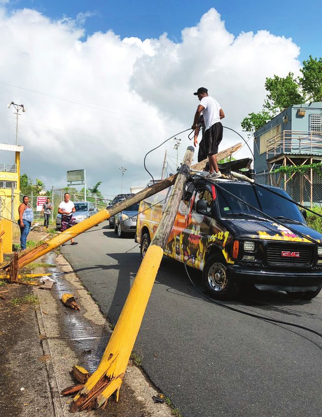
ACKNOWLEDGMENTS

About FCX Solar                                          About Caribbean Electric Utility Services Corporation
Founded in May 2016, FCX Solar is an engineering         (CARILEC) is an association of electric services, dealers,
partnership between Frank Oudheusden and                 manufactures and other stakeholders operating in the
Christopher Needham. Together they have a                electricity industry in the Caribbean region, Central and
combined 20+ years of solar project and project          South America, and globally. The CARILEC Secretariat
development experience ranging from residential to       endeavors to improve communication among its
large-scale utility projects. FCX Solar provides solar   members, providing technical information, training,
power developers and structures manufacturers            capacity building, conference, and other services.
with a wide range of engineering services. FCX           The Secretariat plays a leading role in electric utility
Solar also develops intellectual property in the solar   advocacy, growth, and sustainability in the Caribbean
structures space. Prior to founding FCX, Frank &         region and Central and South America.
Chris were Senior Staff Engineers at SunEdison,
developing in-house proprietary structural products,
vetting all structural products for the global supply
chain, optimizing PV plant design and evaluating new
technologies for M&A opportunities.

About Solar Island Energy
Solar Island Energy is an engineering, construction,
and development services company; expert at
innovative and creative solutions for solar energy,
advanced technology microgrids, and energy
efficiency. Solar Island has a decade of experience in
the Caribbean and is dedicated to helping its clients
to achieve their goals for financial performance and
environmental stewardship.
TABLE OF CONTENTS
01: EXECUTIVE SUMMARY.............................................................................................................................. 05

02: INTRODUCTION............................................................................................................................................10

03: ROOT CAUSE IDENTIFICATION: FINDINGS AND RECOMMENDED PROJECT USE .........13

04: FAILURE MODE AND EFFECTS ANALYSIS (FMEA) .........................................................................16

05: CONCLUSION...............................................................................................................................................24

06: RECOMMENDED REFERENCES.............................................................................................................26

07: APPENDIX: SOLAR PV POWER PLANT WIND PRESSURE
    CHECKLIST FOR PROJECT OWNERS..................................................................................................28

08: ENDNOTES.....................................................................................................................................................32
01            EXECUTIVE SUMMARY

 Hurricane Maria aftermath in Puerto Rico. People attempt to remove broken power poles that landed on top a food truck in Vega Alta, Puerto Rico
EXECUTIVE SUMMARY
    The 2017 hurricane season was one of the most active      by overhead lines. However, in recent years, electricity
    in history.1 Hurricanes Harvey, Irma, and Maria brought   has been supplemented in homes, businesses,
    widespread destruction throughout the Caribbean.          industries, government facilities, and utilities by solar
    In addition to the emotional toll these severe storms     photovoltaics (PV). In fact, over half of Caribbean
    had on people in the region, the disruption of critical   electric utilities already own or operate solar PV as
    infrastructure left many communities without such         part of their generation mix. Over 225 MW of solar is
    basic services as electricity for prolonged periods       installed across rooftops, parking canopies, and large
    of time.                                                  tracts of land. Solar PV is the most rapidly growing
                                                              source of power for many Caribbean islands.2
    Over the past decades, electricity in the Caribbean
    has been primarily generated centrally by fuel oil or
    diesel-fired engines and distributed across the island

    Photo courtesy NASA Earth Observatory

6
EXECUTIVE SUMMARY
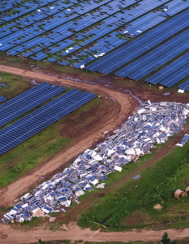
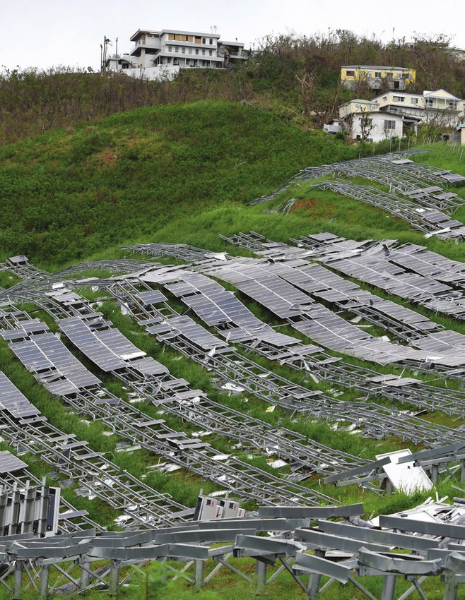
Despite the record sustained wind speeds of over In contrast, some PV systems in Puerto Rico, the US
180 miles per hour, many solar PV systems in the Virgin Islands, and Barbuda suffered major damage or
Caribbean survived. Some solar installations in complete failure with airborne solar modules, broken
the British Virgin Islands, Turks and Caicos, Puerto equipment, and twisted metal racking. 3
Rico, and St. Eustatius faced tremendous wind yet
continued producing power the following day.
FIGURE 1
SURVIVORSHIP AND FAILURE OF GROUND-MOUNT SOLAR PV DURING HURRICANE SEASON 2017
US Virgin British Virgin
Turks & Caicos Puerto Rico Puerto Rico Islands
Islands
St Eustatius
Road Town
Barbuda
Charlotte
Amalie
survive fail
MOUN
KY
TA
ROC
SOLAR UNDER STORM | 7
IN
IN
STIT UTE
EXECUTIVE SUMMARY

           Generating energy with solar PV is a cost-effective           SUMMARY OF FINDINGS:
           and reliable solution for power generation in the             Expert structural engineering teams were deployed to
           Caribbean. Incorporation of the best available                the Caribbean region in the fall of 2017 to investigate
           engineering, design, delivery, and operational                root causes of solar PV system failures in the wake of
           practices can increase the reliability and survival rates     Hurricanes Irma and Maria. They uncovered several
           from extreme wind loading.                                    root causes of partial or full system failure through
                                                                         observation and determined several potential failures
           Given the variability in wind speed, wind                     that could have occurred if other failures did not occur
           direction, wind duration, topography, design, and             first (lurking failure modes).
           construction, along with limited data, we cannot
           give an overarching statistical conclusion to explain         Some similarities of failed systems in the wake of
           survivorship versus failure. Instead, this guide              Hurricanes Irma and Maria:
           combines recent field observations along with expert          1. Top down or T clamp failure of modules
           analysis to deliver actionable recommendations                2. Undersized rack or rack not designed for wind load
           for increasing resiliency among retrofit and new              3. Lack of lateral racking support (rack not properly
           construction solar PV installations.                             designed for wind loading from the side)
                                                                         4. Undersized bolts
           This paper is organized into four sections:                   5. Under torqued bolts
           1. Introduction                                               6. Lack of vibration-resistant connections
           2. Root cause identification methodology and findings         7. PV module design pressure to low for environment
           3. Failure mode and effects analysis (FMEA)                   8. Use of self-tapping screws instead of through bolting
           4. Summary of recommendations
                                                                         Some common ground-mount PV attributes of
           The intended audience for Sections 2 and 3 is                 surviving systems in the wake of Hurricanes Irma
           engineering professionals responsible for PV system           and Maria:
           design, PV system specifications, and/or PV system            1. Dual post piers
           construction oversight and approval. Sections 1               2. Through bolting of solar modules (no top down or
           and 4 are intended for a more general audience of                T clamps)
           governments, utilities, regulators, developers, and PV        3. Lateral racking supports
           system installers who are interested in improving PV          4. Structural calculations on record
           system survivability to intense wind-loading events.          5. Owner’s engineer of record with QA/QC program
                                                                         6. Vibration-resistant module bolted connections
                                                                            such as Nylocs

           Photo courtesy Stephen Mushegan, Clinton Climate Initiative

         MOUN
      KY
             TA
ROC

                                                                                                               SOLAR UNDER STORM | 8
               IN

  IN
       STIT UTE
EXECUTIVE SUMMARY
RECOMMENDATIONS: 2. Collaboration:
The key output of this paper is a list of Collaboration recommendations identify opportunities
recommendations for building more resilient solar for increased resiliency, which require multiparty
PV power plants. The recommendations are consideration and action but do not represent current
organized into two categories: 1) specifications industry standard actions.
and 2) collaboration.
• Collaborate with module suppliers for
1. Specifications: implementation of static and dynamic load tests
•
Specify high-load (up to 5,400 Pa uplift) PV representative of Category 5 hurricane winds.
modules, based on structural calculations; these • Collaborate with racking suppliers for full scale
are currently available from a number of Tier-1 and connection test representative of
module manufacturers. Category 5 winds.
•
Require structural engineering in accordance • Collaborate with equipment suppliers to document
with ASCE 7 and site conditions, with sealed material origin and certificate of grade and
calculations for wind forces, reactions, and coating consistent with assumptions used in
attachment design (ground-mount foundation). engineering calculations.
•
Confirm with racking manufacturer that actual
site conditions comply with their base condition Perhaps the most opportune recommendation is for
assumptions from wind-tunnel testing. a regional and even international community of solar
•
Specify bolt QA/QC process: there were several PV power plant stakeholders who have extreme wind
instances of inadequate torqueing of bolts in the exposure to regularly share lessons learned from new
investigation—a workmanship and oversight issue. designs and extreme wind events. To that end, we
•
Specify bolt hardware locking solution. formed a PV Resiliency working group on the online
•
Specify through bolting of modules as opposed Caribbean Renewable Energy Community (CAREC),
to top-down or T clamps, or if top clamping which is hosted by CARILEC, to connect, innovate,
is required, use clamps that hold modules and collaborate. Join the working group at
individually or independently. http://community.carilec.org/c/PVResiliency.
•
Require structural engineer review of lateral loads
due to racking and electrical hardware—often
lateral loads are missed and recent failures have
proven them to be a critical source of weakness
(e.g., combiner boxes attached to end solar array
posts caused increased loading and led to failure).
•
Do not recommend trackers for projects in
Category 4 or higher wind zones.
•
Specify all hardware be sized based on 25 years
(or project life) of corrosion.
•
Do not recommend any self-tapping screws.
•
Specify dual post fixed tilt ground mounts, which
significantly reduce foundation failure risk.
MOUN
KY
TA
ROC
SOLAR UNDER STORM | 9
IN
IN
STIT UTE02 INTRODUCTION Hurricane Maria aftermath in Puerto Rico. Storm-damaged neighborhood in Corozal, Puerto Rico
INTRODUCTION
           Recently, solar energy has demonstrated increased           Guiding principles of this work include:
           technical and economic ability to support island            1. Collaborate across organizations and expertise.
           communities’ energy transitions. Moreover, solar            2. Address observed failure modes and lurking failure
           energy has demonstrated an ability to withstand major          modes (ones that did not occur only because
           hurricane events despite a portion of the installed            something else failed first).
           base experiencing catastrophic damage. There are            3. Plan for advancement of hardware, reliability
           examples throughout the recent hurricane tracks of             statistics, and expert knowledge.
           Harvey, Irma, and Maria of both survival and failure        4. Provide performance-based recommendations
           of ground-mounted solar PV systems. Given the                  where possible to allow for innovative solutions.
           variability in wind speed, wind direction, topography,      5. Limit recommendations to only those that provide a
           design, and construction, along with limited data, one         risk-adjusted economic benefit.
           overarching conclusion cannot be made to explain the
           diversity of outcomes.                                      In order to realize these guiding principles, we
                                                                       conducted a five-step process:
           The purpose of this document is to combine recent           1. Conduct failure analysis of sites impacted by the
           field observations along with expert analysis to provide       2017 hurricane season.
           actionable recommendations aimed at increasing the          2. Engage experts responsible for managing or
           resiliency of retrofit and new construction solar PV           analyzing historical failures of solar projects.
           installations. More specifically, this paper provides       3. Identify and prioritize root causes through
           guidance applicable to ground-mount and canopy                 collaborative completion of a “fishbone” tool.
           PV power plants with a fixed tilt or a dual tilt (E-W)      4. Complete a failure mode effects analysis (FMEA) for
           configuration. Rooftop systems and tracking systems            the prioritized root causes.
           experience unique aerodynamic phenomena that are            5. Synthesize recommendations from the FMEA for
           not within the scope of this paper but will be addressed       communication and consideration.
           in future versions in response to interest.

           The US Federal Emergency Management Agency
           (FEMA) recently released an advisory regarding rooftop
           PV in the US Virgin Islands that is available online.4
           The advisory is a summary of recommended practices
           for attachment design, installation, and maintenance of
           rooftop solar PV panels to increase the wind resistance
           of panels. This guidance was informed by lessons
           learned after Hurricanes Irma and Maria in 2017
           and is primarily intended for architects, engineers,
           and contractors.

                                                                          Photo courtesy Owen Buggy Photography
           APPROACH
           Our approach to increasing the ability of PV systems to        Necker Island, British Virgin Islands, took a direct
           withstand hurricane winds utilizes design-for-reliability      hit from Hurricane Irma on September 7, 2017. This
           principles and methods.                                        800 kW ground-mount solar PV system survived and
                                                                          powered on the next morning.
         MOUN
      KY
             TA
ROC

                                                                                                                  SOLAR UNDER STORM | 11
               IN

  IN
       STIT UTE
INTRODUCTION
The key output of this paper is a list of ORGANIZATION
recommendations for building more resilient This document is organized to present readers
solar PV power plants. The recommendations are with each of the major analysis steps in order of
organized into two categories: 1) specifications, and 2) completion. Section 2 presents the root cause
collaboration. To the extent possible, the specifications identification methodology and findings, along with
are performance- based to allow for individual project recommendations for using the findings and the
teams to provide the most cost-effective and method. Section 3 utilizes the root causes identified
resilient solution. Collaboration recommendations in an FMEA. The output of this analysis includes
identify opportunities for increased resiliency, which potential mitigation actions that are evaluated by cost
require multiparty consideration and action but do not and impact. Section 4 synthesizes mitigation actions
represent industry standard actions. identified in the FMEA into a list of recommendations
for ease of communication and consideration by
Perhaps the most opportune recommendation is for the reader.
a regional and even international community of solar
PV power plant stakeholders who have extreme wind
exposure to regularly share lessons learned from new
designs and extreme wind events. To that end, we
formed a PV Resiliency working group on the online
Caribbean Renewable Energy Community (CAREC),
which is hosted by CARILEC, to connect, innovate,
and collaborate. The working group can be found at
community.carilec.org/pv-resilency.
MOUN
KY
TA
ROC
SOLAR UNDER STORM | 12
IN
IN
STIT UTE03 ROOT CAUSE IDENTIFICATION:
FINDINGS AND RECOMMENDED
PROJECT USE
Photo by Kenneth Wilsey - Feb 13, 2018 Guaynabo, Puerto RicoROOT CAUSE IDENTIFICATION:
FINDINGS AND RECOMMENDED PROJECT USE
The recent hurricane season in conjunction with the Continuing the Conversation, Community of Practice
increased installed base of solar power plants has Project teams that complete a root cause analysis
provided an initial body of evidence for developing are invited to create their own fishbone diagram for
resiliency guidelines for future projects. However, sharing with the Caribbean Community of Practice—
development of hurricane resiliency guidelines based the CARILEC Renewable Energy Community, (CAREC).
on observed failure modes alone has limitations. RMI will compile your findings annually with those of
The observed failure modes may have served as a other participating project teams. Participating teams
“mechanical fuse” relieving forces from the system. will be invited to an exclusive webinar for sharing
In the event that future systems only address the best practices across teams. To join CAREC, go to
observed failure modes, forces may precipitate community.carilec.org.
additional failure modes. To address both observed
and potential failure modes, we take a classical
reliability engineering approach to design for reliability.
Figure 2 illustrates a common reliability tool for
systematic cause and effect identification called a
fishbone diagram. The diagram shows the supply
chain responsible for design, manufacturing,
procurement, delivery, installation, and operations of a
solar power plant, along with the operational use case.
The most urgent causes of failure are in bold text.
The current fishbone draft is limited by the data
set, authors’ expertise, and current technology;
consequently, this analysis should be updated to
incorporate new data, expertise, and technology.
Future solar power plant project teams are invited
to utilize Figure 2 as a facilitation tool to explore
project-specific opportunities to eliminate causes
of failure in response to extreme wind or other
hazards. During a project delivery process, the project
team may explore the categories provided along with
additional categories to identify causes of failure and
potential mitigations. Project teams that complete the
root cause analysis are invited to annotate Figure 2
and share their findings with the broader community.
MOUN
KY
TA
ROC
SOLAR UNDER STORM | 14
IN
IN
STIT UTEROOT CAUSE IDENTIFICATION: FINDINGS AND RECOMMENDED PROJECT USE
FIGURE 2
FISHBONE DIAGRAM FOR ROOT CAUSE ANALYSIS IDENTIFICATION
Construction
Materials Equipment People
Methods
Owner’s Project
Metal Grade Module hardware Documentation Engineer
Design life Training Developer
Coatings
Reliability Testing Means & Methods Local Inspectors
Quality
Certifications Warranty Management Construction Labor
HURRICANE FAILURE
Corrosivity UL Component Equipment
Till/Tracking Certifications Transaction
Topography AISC Steel Design
Construction
Orientation Code
Agreement
Soils & Erosion
ASCE Building Code
Row Spacing Service Agreement
Wind Member & Code Version (year) Procurement
Connection Sizing
Turbulence
Process
Direction
Speed
Code Enforcement
Codes and
Environment System Design Business Model
Standards
MOUN
KY
TA
ROC
SOLAR UNDER STORM | 15
IN
IN
STIT UTE04 FAILURE MODE AND EFFECTS
ANALYSIS (FMEA)
Photo by Kenneth Wilsey for FEMA - Humacao, Puerto Rico, Jan. 25, 2018FAILURE MODE AND EFFECTS
ANALYSIS (FMEA)
Improving the ability of PV systems to withstand
hurricane winds requires not only identification of
failure modes but also a cost-effective mitigation
action. We utilized the FMEA framework to identify
practical mitigation actions. Moreover, we aspired to
provide actions that have a net positive impact on
cost when considering the cost and benefit in a risk-
adjusted financial analysis.
The synthesis of the FMEA presented below is
designed to teach a user the current mitigation and
associated limitations of the most relevant failure modes
and also to provide a cost-effective mitigation action.
The table is organized by subsystems and assemblies.
MOUN
KY
TA
ROC
SOLAR UNDER STORM | 17
IN
IN
STIT UTEFAILURE MODE AND EFFECTS ANALYSIS (FMEA)
TABLE 1
PV MODULE FRAME AND LAMINATE
FAILURE CURRENT COST/
# LIMITATIONS POTENTIAL MITIGATION ACTION
MODE(S) MITIGATION IMPACT
Laminate tear- UL 1703 static Local pressure Review racking system/full structural system wind Low/Medium
out (module load (global PV may exceed tunnel test report for local wind pressure and
glass dislodged module testing module rated compare against module front and back rated
from frame) standard) pressure pressure. Refer to example in Appendix A. Racking
1a
suppliers furnish these wind tunnel test reports
upon request. Results of the test will determine
the proper rating for modules (which will differ
across the design of the array).
Frame bolt hole Engineering Module back Specify engineer calculations for module Low/High
failure connection side (uplift connection hardware, including frame where
calculations force) rating used.
may not be
1b adequate for Collaborate with module manufacturers to
local loads improve supply chain.
Engineer of record for the project should request
and approve engineering connection calculations.
Laminate UL 1703 hail Hurricane Specify that site prep and clean-up shall include Low/High
impact damage impact tests debris can be removal or securement of all foreign objects
and ASCE wind- large compared (debris).
prone debris. to hail
1c
Some severe
hail-damaged
modules are
available
Photo courtesy FCX Solar
MOUN
KY
TA
ROC
SOLAR UNDER STORM | 18
IN
IN
STIT UTEFAILURE MODE AND EFFECTS ANALYSIS (FMEA)
TABLE 2
PV MODULE CONNECTION HARDWARE
FAILURE CURRENT COST/
# LIMITATIONS POTENTIAL MITIGATION ACTION
MODE(S) MITIGATION IMPACT
Bolt self- Partial Self-loosening Specify bolt locking solution appropriate for the Low/High
loosening torque check common due environment and workforce. (Nyloc nuts have
and proper to washer- been anecdotally reported to provide mitigation
2a documentation clamping even when not torqued properly.)
of the torque surface
checks translation
during vibration
Connection SE hand Hand Specify SE site-specific review of module Low/High
hardware calculations are calculations attachment hardware per AISC or equivalent.
failure typical not always
2b (fracture, updated with
rupture, tear site-specific
out, shear) wind load and
topography
Cascading Module Module T Specify module frames to be through bolted in Low/High
failure of T T clamps clamps rotate accordance with manufacturing specification
clamps designed for with loss of one for the design wind speed. If necessary, use top
2c symmetric module and clamps that do not allow cascading failure.
boundary allow liberation
conditions of second
module
Photos courtesy FCX Solar
MOUN
KY
TA
ROC
SOLAR UNDER STORM | 19
IN
IN
STIT UTEFAILURE MODE AND EFFECTS ANALYSIS (FMEA)
TABLE 3
STRUCTURAL RACKING MEMBER
FAILURE CURRENT COST/
# LIMITATIONS POTENTIAL MITIGATION ACTION
MODE(S) MITIGATION IMPACT
Member global Steel code ASCE 7 1. Utilize owner’s project engineer to review 1. Low/Medium
failure (plastic (AISC or prioritizes calculation package. 2. Med/High
deflection, equivalent) normal 2. Specify racking design for the wind speed 3. Low/High
buckling, check with loads due recommended by ASCE 7-16. 4. Low/Medium
torsion) software to buildings 3. Specify SE review of lateral loads due to 5. Medium
3a package (RISA focus. Lateral racking and eBoS hardware. (Tracking
3D or equiv.) loads on eBoS 4. Specify racking with documentation of full only)
and updated commonly scale load test.
according to omitted 5. Specify any tracker included in the project shall
site-specific be designed for worst case wind exposure, no
ASCE 7 loads stow position for extreme wind allowed.
Dynamic Building code PV arrays SE project engineer should check dynamic
excitation requires with inter- loading if resonant frequency isFAILURE MODE AND EFFECTS ANALYSIS (FMEA)
TABLE 4
STRUCTURAL RACKING CONNECTIONS
FAILURE CURRENT COST/
# LIMITATIONS POTENTIAL MITIGATION ACTION
MODE(S) MITIGATION IMPACT
Bearing AISC check Hand Specify structural engineer to complete site- Low/High
bolt shear with hand calculations not specific connection review
calculations always updated
4a
typical with site-
specific wind
loads
Bolt self- Partial torque Self-loosening Specify bolt-locking solution appropriate for the Low/High
loosening check and common due environment and workforce.6
documentation to washer-
4b typical clamping
surface
translation
during vibration
Self-tapping Steel code Sizing does Either specify no self-tapping screws or specify Low/High
screw corrosion not always self-tapping screws to be sized based on 25 years
4c and shear account for and for expected vibrations.
failure highly corrosive
environment
Left photo courtesy NREL; Right photo courtesy FCX Solar
MOUN
KY
TA
ROC
SOLAR UNDER STORM | 21
IN
IN
STIT UTEFAILURE MODE AND EFFECTS ANALYSIS (FMEA)
TABLE 5
RACKING FOUNDATIONS
FAILURE CURRENT COST/
# LIMITATIONS POTENTIAL MITIGATION ACTION
MODE(S) MITIGATION IMPACT
Foundation ASCE 20 Requires Specify complete suite of geotechnical test for Medium/
structural site-specific foundation design. Medium
5a
failure geotechnical
data
Overturning Structural Developers Specify structures with dual foundation designs Medium/High
foundation design want to over single foundation designs as they better
5b posts preferences minimize support from an overturning moment failure.
foundations Specify low tilt angles to reduce peak module
per site pressures and overturning moments.
Erosion Very few Requires water On steep-slope, loose-soil projects, develop Medium/
drainage water drainage plan and install drainage methods Medium
5c control plan during site construction to control water flow.
Take into account topography from surrounding
land that isn’t site specific.
Corrosion American More For foundations: Medium/
Galvanizers galvanization Specify testing of soil corrosion (pH, chloride, Medium
Association requires and moisture) at multiple locations and utilize for
Guidance more cost foundation design according to ASTMA123.
5d
Be familiar with causes of accelerated corrosion
like pollution, humidity, and salt water proximity
and review the local (300 m radius) area for
caustic-causing input to the plant.
Photo courtesy AquaSoli
MOUN
KY
TA
ROC
SOLAR UNDER STORM | 22
IN
IN
STIT UTEFAILURE MODE AND EFFECTS ANALYSIS (FMEA)
TABLE 6
ELECTRICAL BALANCE OF SYSTEMS
FAILURE CURRENT COST/
# LIMITATIONS POTENTIAL MITIGATION ACTION
MODE(S) MITIGATION IMPACT
Wire pull out UL specification Terminal Specify QA/QC procedure and documentation for Low/Low
or terminal for each torque values terminal torques.
damage electrical unchecked in
6a
component field
(e.g., UL 1703
PV modules)
Wire sheath NEC or IEC Wires sag Specify wire management practices, including Low/Low
chafing (ground conductor and subject support schedule and sag tolerance.
fault) management to gyration
6b
and support based on field Specify stainless-steel or heavily galvanized wire
specifications installation clips or PVC coated stainless-steel cable clamps
instead of plastic zip ties.
Wire NEC or IEC Direct and Specify UV-resistant and corrosion-resistant wire Low/Low
management reflected UV management solution.
fracture exposure
increases Require plan set to incorporate wire management
6c risk of technique for review against NEC or IEC.
embitterment
and fracture Specification of conduit in lieu of open-air wire
management may be appropriate in some
locations.
Rain intrusion NEC - NEMA Hurricane Specify NEMA 4X to 6P enclosures based on Medium/High
into combiner specification wind blowing engineering review. IEC equivalent is IP56 to IP67.
6d boxes or sideways can
inverters penetrate
NEMA 3
Photos courtesy FCX Solar
MOUN
KY
TA
ROC
SOLAR UNDER STORM | 23
IN
IN
STIT UTE05 CONCLUSION
CONCLUSION
           Generating energy with solar PV is a cost-effective                •   Specify all hardware be sized based on 25 years
           and reliable solution for power generation in the                      (or project life) of corrosion.
           Caribbean. Incorporation of the best available                     •   Do not recommend any self-tapping screws.
           engineering, design, delivery, and operational                     •   Specify dual post fixed tilt ground mounts, which
           practices can increase the reliability and survival rates              significantly reduce foundation failure risk.
           from extreme wind loading.
                                                                          Likely the most effective strategies for improving
           This paper is limited in its ability to be omniscient of all   system survival rates are communicating clear market
           failure modes and all corrective actions, and cannot           signals to suppliers and upstream equipment providers
           guarantee the efficacy of any recommended action.              and coordinating closely among practitioners.
           However, it provides a set of best practices regarding         This includes:
           specifications of equipment and procedures along
           with a framework for continued collaboration within a          •   Collaboration with module suppliers for
           community of practice.                                             implementation of static and dynamic load tests
                                                                              representative of Category 5 hurricane winds.
           Specifications include:                                        •   Collaboration with racking suppliers for full scale and
                  •
               Specify high-load (up to 5,400 Pa uplift) PV                   connection test representative of Category 5 winds.
               modules, based on structural calculations; these           •   Collaboration with equipment suppliers to
               are currently available from a number of Tier-1                document material origin and certificate of grade
               module manufacturers.                                          and coating consistent with assumptions used in
                  •
               Require structural engineering in accordance                   engineering calculations.
               with ASCE 7 and site conditions, with sealed
               calculations for wind forces, reactions, and               If successful, this paper will be one of the early actions
               attachment design (ground-mount foundation).               that triggers more effective coordination across supply
                  •
               Confirm with racking manufacturer that actual              chains and the community of practice.
               site conditions comply with their base condition
               assumptions from wind-tunnel testing.
                  •
               Specify bolt QA/QC process: there were several
               instances of inadequate torqueing of bolts in the
               investigation—a workmanship and oversight issue.
                  •
               Specify bolt hardware locking solution.
                  •
               Specify through bolting of modules as opposed
               to top-down or T clamps, or if top clamping
               is required, use clamps that hold modules
               individually or independently.
                  •
               Require structural engineer review of lateral loads
               due to racking and electrical hardware—often
               lateral loads are missed and recent failures have
               proven them to be a critical source of weakness
               (e.g., combiner boxes attached to end solar array
               posts caused increased loading and led to failure).
                  •
               Do not recommend trackers for projects in
               Category 4 or higher wind zones.
         MOUN
      KY
             TA
ROC

                                                                                                                  SOLAR UNDER STORM | 25
               IN

  IN
       STIT UTE
06 RECOMMENDED REFERENCES Photo courtesy Stephen Mushegan, Clinton Climate Initiative
RECOMMENDED REFERENCES
           Solar PV in the Caribbean – Opportunities and
           Challenges
           http://bpva.org.uk/media/107431/solar-pv-in-the-
           caribbean.pdf

           FEMA Advisory: Rooftop Solar Panel Attachment:
           Design, Installation, and Maintenance
           https://www.fema.gov/media-library/assets/
           documents/158123

           Wind Loads for Utility Scale Photovaltic Power Plants,
           Joe Cain and David Banks
           https://www.seia.org/sites/default/files/Cain%20
           and%20Banks%20Utility%20Scale%20Wind%20
           Presentation%202015%20SEAOC%20Convention.pdf

           “Solar Panels Destroyed by Hurricane Maria Litter         The 5 MW Estate Donor Solar Project on the island of St. Thomas.
                                                                     Photo courtesy Jennifer DeCesaro
           a Solar Farm on the Grounds of the U.S. Federal
           Courthouse in Christiansted,” Reuters
           http://news.trust.org/item/20170928032254-655rq

           “After Four Months, Much of Puerto Rico Still Dark and
           Damaged,” The Atlantic
           https://www.theatlantic.com/photo/2018/01/after-
           four-months-much-of-puerto-rico-still-dark-and-
           damaged/551756/

           “Solar Survives the Storms in Puerto Rico,” PV Magazine
           https://pv-magazine-usa.com/2017/11/07/solar-
           survives-the-storms-in-puerto-rico/

         MOUN
      KY
             TA
ROC

                                                                                                                 SOLAR UNDER STORM | 27
               IN

  IN
       STIT UTE
07 APPENDIX: SOLAR PV POWER PLANT WIND
PRESSURE CHECKLIST FOR PROJECT OWNERSAPPENDIX: SOLAR PV POWER PLANT WIND
PRESSURE CHECKLIST FOR PROJECT OWNERS
The determination of a design wind pressure is a that do not have a dedicated table, rounding down
complex science conducted by expert scientists and should provide a near approximation as long as
engineers. Solar PV power plant owners may generally the aspect ratio and location are also similar. If an
confirm that wind pressures have been appropriately appropriate table does not exist, the wind tunnel
determined through familiarization with the process. can most likely reprocess existing data with minimal
time and resources.
General process for solar PV power plant wind
pressure determination: 3. Determine the wind dynamic pressure by
accounting for the design wind speed, local
1. Conduct wind tunnel study on a scaled system topography, system height, directionality,
model in a boundary-layer wind tunnel. and importance.
Project stakeholders may review the wind tunnel Project stakeholders should be able to review
test report to confirm the scale model represents a site-specific determination of wind dynamic
the project’s proposed system layout. Deviations in pressure. The calculation should comply with
row length, spacing, tilt, height, and leading-edge the governing code and version (e.g., ASCE 7-10)
height should be limited to the range identified in and incorporate the regional design wind speed,
the wind tunnel report. system height, topography, and importance.
Projects with any topographic features should
ensure appropriate treatment of said features.
4. Combine the pressure coefficients and dynamic
pressure to calculate a wind pressure.
Project stakeholders should be able to review
structural calculation to determine a design wind
pressure for each component or member of
interest. Figure 3 illustrates a set of wind pressures
for design wind speeds of 165 and 185 mph for
pressure coefficients from 0 to 2.5. In this example,
a pressure coefficient of 0.5 corresponds to design
pressures less than 2,000 Pa (Pascals, 49 Pa =
1 PSF). In contrast, a pressure coefficient of 2.5
Photo courtesy Stephen Mushegan, Clinton Climate Initiative corresponds to design pressures in excess of 7,000
Pa. Given the potential variability, one can not
2. Analyze pressure measurements to determine assume that a high load rating module is either
pressure coefficients for the module or structural necessary or adequate.
member of interest.
The wind tunnel test report should contain a table
of pressure coefficients for each structural member
of interest corresponding to the tributary area of
said member or component. A project stakeholder
should be able to identify that an appropriately
selected table of pressure coefficients was used
for each member or component. For components
MOUN
KY
TA
ROC
SOLAR UNDER STORM | 29
IN
IN
STIT UTEAPPENDIX
FIGURE 3
SAMPLE EXTREME WIND UPLIFT PRESSURE ON MODULE SURFACE
Internal Pressure Coefficients = Gcn
Gcn- = -0 Gcn- = -0.5 Gcn- = -1 Gcn- = -1.5 Gcn- = -2 Gcn- = -2.5
0
0 0
-1,000
-1418
-2,000
Pascals or Pa from -1,000 to -10,000
-1783
-3,000 -2836
-3566
-4,000
-4255
-5,000
-5349
-6,000 -5673
-7,000
-7132 -7091
-8,000
-9,000 -8914
-10,000
P @ 165 (Pa) P @ 185 (Pa)
5. Review component and member specifications.
Project stakeholders should be able to review product
specifications or engineering sets for all structural
components, members, and connectors, including
PV modules. Figure 4 illustrates the specification
from a module that has one of the highest structural
capacities known to the authors. Key information in this
specification includes the range of allowable support
conditions (AI) along with the specific AND unique
uplift load.
MOUN
KY
TA
ROC
SOLAR UNDER STORM | 30
IN
IN
STIT UTEAPPENDIX
FIGURE 4
PV MODULE MOUNTING SPECIFICATION
A1 A1
Use four clamps on the long side. Mounting rails
run perpendicularly to the long side frame.
A1 range= (300–330)mm
Maximum Load:
Uplift load < 4,000 Pa
Downforce load < 8,100 Pa
A1 A1
MOUN
KY
TA
ROC
SOLAR UNDER STORM | 31
IN
IN
STIT UTE08 ENDNOTES
ENDNOTES
           1
            “2017 Atlantic Hurricane Season Now Seventh Most
           Active in History”, The Weather Channel
           https://weather.com/amp/storms/hurricane/
           news/2017-10-09-atlantic-hurricane-season-one-of-
           busiest-october.html

           2
            Castalia Advisors: “Castalia presents the 6th annual
           Renewable Islands Index and Marketplace at CREF”
           http://www.castalia-advisors.com/news_at_castalia.
           php&news_id=263

           3
            “In the Virgin Islands, Hurricane Maria
           Drowned What Irma Didn’t Destroy,” NY Times
           https://www.nytimes.com/2017/09/27/us/hurricane-
           maria-virgin-islands.html

           4
            FEMA: Hurricanes Maria and Irma
           https://www.fema.gov/media-library/assets/
           documents/158123

           5
            “Hazards by Location,” Applied Technology
           Council (ATC)
           https://hazards.atcouncil.org/#/
           wind?lat=14.090663655484727&lng=-
           60.95692034374997&address=

           6
            Richard T Barrett, “Fastener Design Manual,” NASA
           Reference Publication 1228 (1990).
           https://ntrs.nasa.gov/archive/nasa/casi.ntrs.nasa.
           gov/19900009424.pdf

         MOUN
      KY
               TA
ROC

                                                                   SOLAR UNDER STORM | 33
                 IN

  IN
       STIT UTE
MOUN
KY
TA
ROC
IN
IN
STIT UTE
22830 Two Rivers Road
Basalt, CO | 81621 USA
www.rmi.org
© June 2018 RMI. All rights reserved. Rocky Mountain Institute® and RMI® are registered trademarks.You can also read