North East Levin Stormwater - goodearthmatters.com - Horizons Regional Council
←
→
Page content transcription
If your browser does not render page correctly, please read the page content below
North East Levin Stormwater

Erosion and Sediment Control Plan: Tributary Crossings & Attenuation Areas 3
and 4; Koputaroa Stream Tributary
July 2021

Horowhenua District Council

v3 Draft for Consenting

                                                  goodearthmatters.com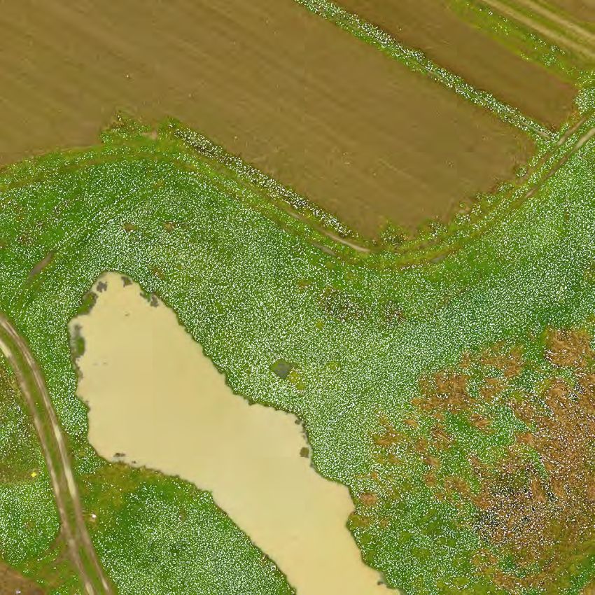
This report has been prepared by Good Earth Matters Consulting Limited on behalf of the client and for the
 purpose outlined in the project scope. This report is provided for use by the client, their professional advisors
 and local body authorities for consenting purposes (if applicable). Good Earth Matters Consulting Limited does
 not accept any liability if this report is used for an alternative purpose from which it is intended, nor to any
 third party in respect of this report. No liability is accepted by any employee or sub-consultant of
 Good Earth Matters Consulting Limited.

 Client:                 Horowhenua District Council
 Report Title:           Erosion and Sediment Control Plan: Tributary Crossings & Attenuation Areas 3 and 4;
                         Koputaroa Stream Tributary
 File Reference:         27019\2021.07 NE Levin Stage 2 ESCP - DRAFT.docx
 Report Issue:           v3 Draft for Consenting                        Date:    July 2021
                         V2 Draft for Consenting                                 September 2018
                         Draft for Consenting                                    June 2018

 Prepared:               Good Earth Matters Consulting Limited          Date:    July 2021

 Authorised for Issue:                                                  Date:    July 2021
                         Annette Sweeney

 On behalf of:           Good Earth Matters Consulting Limited

P 06 3537560                       contact@goodearthmatters.com                           goodearthmatters.com
TABLE OF CONTENTS

1   INTRODUCTION.................................................................................................................................1
2   DESCRIPTION OF WORKS TO BE UNDERTAKEN UNDER THIS ESCP ..................................................1
3   PRINCIPLES FOR EROSION & SEDIMENT CONTROL ..........................................................................3
    3.1 Minimising Disturbance ..........................................................................................................................3
    3.2 Earthworks Staging..................................................................................................................................4
    3.3 Protect Steep Slopes ...............................................................................................................................4
    3.4 Protect Water Bodies ..............................................................................................................................5
    3.5 Stabilisation of Exposed Areas ................................................................................................................5
    3.6 Installing Perimeter Controls ..................................................................................................................5
    3.7 Dust Control ............................................................................................................................................5
    3.8 Detention Devices ...................................................................................................................................5
    3.9 Inspection ................................................................................................................................................6
    3.10 Evolution of the Plan ...............................................................................................................................6
4   EROSION AND SEDIMENT CONTROL METHODS ...............................................................................6
    4.1 Top Soiling ...............................................................................................................................................6
    4.2 Re-Vegetation .........................................................................................................................................7
    4.3 Silt Fence .................................................................................................................................................7
    4.4 Scour Protection ......................................................................................................................................8
    4.5 Stabilised Construction Entrance ............................................................................................................8
    4.6 Clean Water Cut-Offs ..............................................................................................................................9
5   MAINTENANCE, MONITORING AND REPORTING .......................................................................... 13
6   HEAVY RAINFALL RESPONSE AND CONTINGENCY MEASURES ...................................................... 13
7   SITE RESPONSIBILITIES ................................................................................................................... 14

Appendices

Appendix A            Erosion & Sediment Control Plans
Appendix B            Factsheets referenced by Horizons Regional Council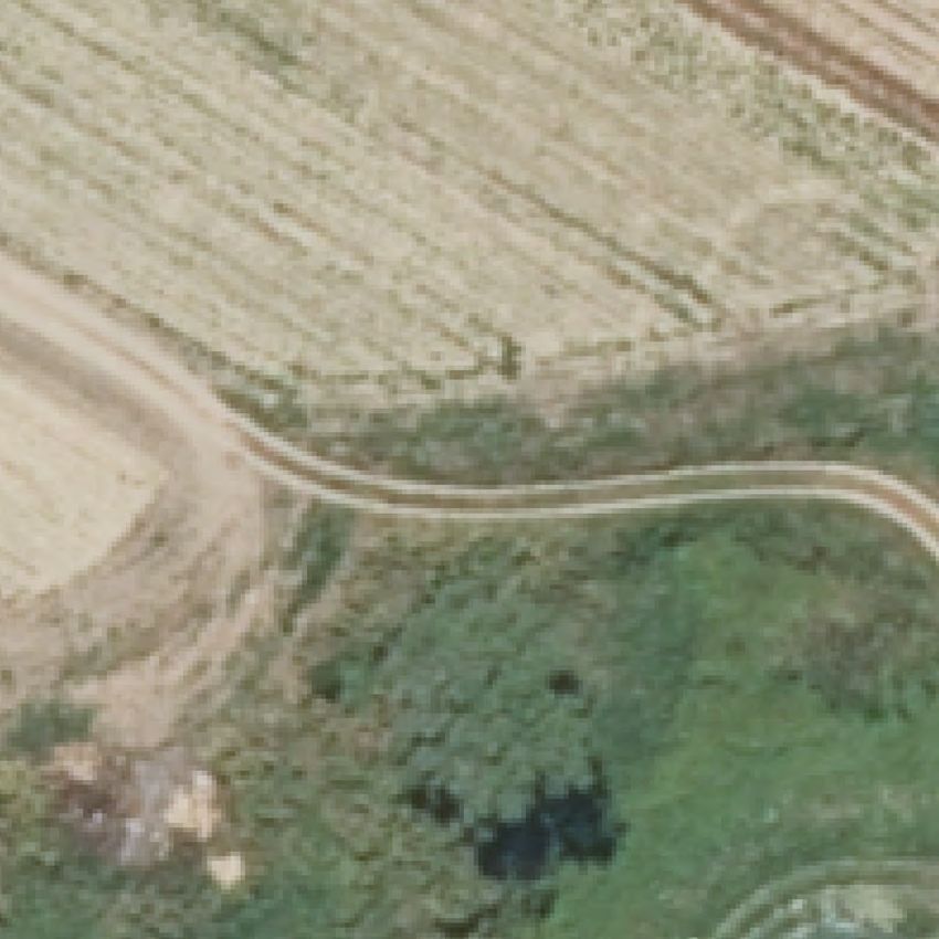
1       INTRODUCTION
        This Erosion and Sediment Control Plan (ESCP) outlines the proposed controls to minimise erosion and
        control sediment from stormwater runoff during the undertaking of proposed earthworks following
        the upper reaches of the Koputaroa Stream tributary, from the site of 181 Roslyn Road, Levin through
        to 259 State Highway 57, Levin. These earthworks shall provide attenuation volume to mitigate
        potential adverse effects of Levin stormwater discharge on downstream properties, before
        discharging to the northeast into the Koputaroa Stream tributary.

        The proposed attenuation areas will provide sufficient storage in order to achieve hydraulic neutrality
        with respect to peak flows.

        Scope and Version Control
        This ESCP relates to the stream crossings, culvert upgrades, embankments for creating attenuation
        areas, and earthworks to be undertaken to increase attenuation volume capacity. Earlier versions (v1,
        v2) of this ESCP detailed the necessary controls for an earlier proposal of the attenuation system. In
        2021, it was identified that larger attenuation volumes were required to achieve hydraulic neutrality
        (as documented in consent s92 information responses) and, as a result, the required earthworks
        volume has increased. The ESCP has therefore been updated (v3, July 2021) to ensure that the
        proposed erosion and sediment control measures are appropriate for preventing adverse effects in
        terms of sedimentation during the construction phase.

        A separate ESCP has been prepared with respect to the first attenuation area, known colloquially as
        Coley Pond. The earthworks requirements for Coley Pond have not changed significantly and
        therefore updating of the ESCP for Coley Pond is not required.

        Both the Coley Pond and this ESCP are prepared as draft for consenting purposes. This is standard
        practice for consenting matters, with the ESCP to be finalised and submitted for technical certification
        as a condition of consent.

2       DESCRIPTION OF WORKS TO BE UNDERTAKEN UNDER THIS ESCP
        The subject site is situated along the watercourse of the Koputaroa Stream tributary, across several
        properties to the northeast of the intersection between Fairfield Road and Roslyn Road.

        The earthworks shall be undertaken at five (5) distinct sites, along a tributary which has been highly
        modified, with areas of wet weeds in the natural low points of the site. There are very few trees on
        site, and no ecologically significant areas in the surrounding vicinity, including downstream.

        The existing topography is generally flat over most of the site apart from the existing watercourse. The
        immediately adjacent ground is graded/contoured down towards the watercourse base.

        The sites, and the proposed earthworks are as follows:
        1.   Crossing No 1: This is a stream crossing / culvert upgrade and does not involve any significant
             earthworks. These works are not required to give effect to the current proposal but may be
             undertaken if agreed and requested by the landowner. Works at this site are unchanged from
             that detailed in the earlier version of this ESCP.
        2.   2nd Embankment: This was an embankment and culvert upgrade which was proposed to create
             the formerly proposed 2nd Attenuation Area. The 2nd Attenuation Area is no longer proposed
             and any works in this area would only be undertaken to provide improved access across the
             stream for the landowner if so requested. The works are the embankment only and do not involve

V3 DRAFT FOR CONSENTING                                                                                  Page 1
any significant earthworks. These works are not required to give effect to the current proposal.
              If works are undertaken at this site, the scope and erosion and sediment control measures are
              unchanged from that detailed in the earlier version of this ESCP.
         3.   3rd Attenuation Area and Embankment. An embankment is proposed which will create an
              attenuation area during times of high rainfall and stormwater runoff. The embankment
              construction is generally as per the earlier proposal and the way in which these works across the
              stream will be undertaken is as per the earlier version of this ESCP. Earthworks off the water
              course were previously proposed to increase attenuation. This remains the proposal, with the
              change being an increase in the footprint and volume of earthworks, with increased attenuation
              provided within the previously indicated area, as well as earthworks along the true left side of the
              watercourse. As the attenuation volume to be provided is being created above normal water
              level (so that normal water flows are not altered), it follows those earthworks will generally be
              undertaken above water level and in the dry, albeit along the margins of the watercourse. The
              earthworks extent in this area is approximately 15,000 m3, and the earthworks footprint is less
              than 12,500 m2. (The final top water level of the attenuation area when full is 12,500 m2, and this
              includes the existing watercourse area).
         4.   4th Attenuation Area and Embankment. An embankment is proposed which will create an
              attenuation area during times of high rainfall and stormwater runoff. The embankment
              construction is generally as per the earlier proposal and the way in which these works across the
              stream will be undertaken is as per the earlier version of this ESCP. Minor earthworks off the
              water course were previously proposed to increase attenuation. This remains the proposal, with
              the change being an increase in the footprint and volume of earthworks, with increased
              attenuation provided within the previously indicated area, as well as earthworks along the true
              left side of the watercourse. As the attenuation volume to be provided is being created above
              normal water level (so that normal water flows are not altered), it follows those earthworks will
              generally be undertaken above water level and in the dry, albeit along the margins of the
              watercourse. The earthworks extent in this area is approximately 2,700 m 3, and the earthworks
              footprint is less than 3,000 m2. (The final top water level of the attenuation area when full is
              3,000 m2, and this includes the existing watercourse area).
         5.   Crossing No 2: This is a stream crossing / culvert upgrade and does not involve any significant
              earthworks. These works have been agreed with the landowner. Works at this site are unchanged
              from that detailed in the earlier version of this ESCP.

         The works to be undertaken at the site will generally be as follows:
         •    Install ESC devices including perimeter (upstream) cut-off drains, silt fencing to watercourse at
              the side boundaries of each distinct site and stabilised construction entrance(s).
         •    The majority of earthworks areas are less than 3,000 m2 and therefore do not require detention
              and decant outlets. Earthworks will be progressively undertaken and stabilised in order to
              minimise the extent of exposed area to less than 3,000 m2 unless detention and decanting is
              provided. On the true left of the tributary at Attenuation Area 3, the earthworks footprint exceeds
              the 3,000 m2 threshold and a detention pond and decant is to be installed as per Horizons
              Sediment Retention Pond guidelines attached as Appendix B.
         •    Topsoil stripping and stockpiling
         •    Bulk earthworks, excavation to create proposed attenuation areas and culvert embankments
         •    Stabilisation and establishment of grass cover
         •    Removal of ESC devices
         •    Planting of excavated attenuation areas

Page 2                                                                              V3 DRAFT FOR CONSENTING
The sites receive water from a culvert through the downstream embankment of the first attenuation
area (Stage 1) (which is received as stormwater from the residential area) plus any runoff from the
adjacent paddocks.
The works of this stage of stormwater attenuation areas are intended to be undertaken in a period(s)
of sustained dry weather. The 'Stage 1' stormwater treatment and attenuation area (Coley Pond) shall
enable significant catchment of stormwater volume in the occurrence of any rain events during the
earthworks, allowing the watercourse through the site to be effectively managed at minimum water
flows. That is, the works which are subject to this ESCP will be undertaken after completion of Coley
Pond and therefore there will be some opportunity to hold back stormwater from small events in
Coley Pond through manual manipulation of the Coley Pond outlet structure such that the water levels
through the works areas can be controlled (with the exception of a significant storm event) while
works are being undertaken in close proximity to the watercourse.
No winter works are proposed and no works will be undertaken between 1 May and
30 September in any year.
3 PRINCIPLES FOR EROSION & SEDIMENT CONTROL
This ESCP identifies and outlines systems to minimise surface erosion during the execution of the
earthworks and to deal with any sediment that is transported by rainfall-generated runoff. This will
reduce the impact of the earthworks both across the site and within the watercourse. The principles
to be followed are:
3.1 Minimising Disturbance
The areas of earthworks will be limited to within the confines of the attenuation areas and dam
embankments as much as possible. The existing wet areas within the watercourse are generally at the
base level of the proposed earthworks. There will be no need to disturb these areas other than for
weed clearance, which will generally be undertaken by excavator from the banks of the watercourse.
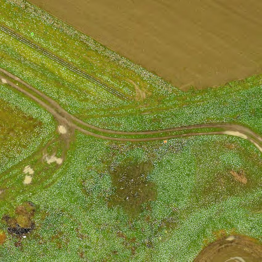
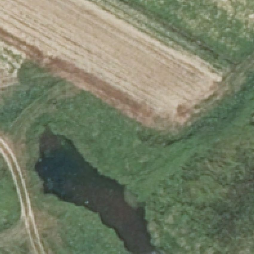
The principal areas of earthwork excavation will be to increase the storage volumes of the third
attenuation area, shown in Figures 3.1 and 3.2, and the fourth attenuation area, shown in Figure 3.3.
Figure 3.1
Third Attenuation Area to be Excavated, View to North
V3 DRAFT FOR CONSENTING Page 3
Figure 3.2
         Third Attenuation Area to be Excavated, View to North-East
         (True left side of current watercourse area. Watercourse in growth of Raupo)

         Figure 3.3
         Fourth Attenuation Area to be Excavated, View to North
         (From True right side of current watercourse, Excavation area opposite side)

         Assessment by ecologists consulted by both Horowhenua District Council and Horizons have
         determined that there is less than minor ecological value in existing vegetation at sites of the third and
         fourth attenuation areas. The fourth attenuation area, as expanded in the current proposal, has been
         specifically designed to avoid established plantings. Disturbance of existing vegetation will be
         minimised as practicable, and any vegetation lost during excavation and construction of embankments
         can be addressed by replanting.

         The limits of earthwork disturbance shall be generally as shown in site plans provided in Appendix A.
         On site these limits of disturbance will be marked by pegs and/ or temporary fences as needed.

3.2      Earthworks Staging
         Earthworks of each geographically separate attenuation area will be completed and replanted in turn,
         to minimise open areas as much as possible. For all but the true-left Attenuation Area 3 site, the
         earthworks areas are under the 3,000 m2 threshold and a retention pond is not required. A sediment
         retention pond is proposed for the true-left side of Attenuation Area 3 as discussed below.

3.3      Protect Steep Slopes
         The site topography is generally very flat. In this regard, there are no steep slopes currently on the
         site.

Page 4                                                                               V3 DRAFT FOR CONSENTING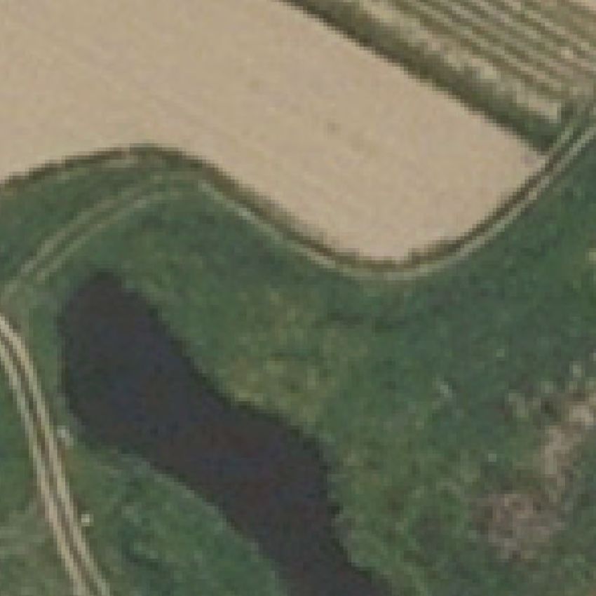
3.4     Protect Water Bodies
        As stated above, the works of this stage of stormwater attenuation areas are intended to be
        undertaken in a period(s) of sustained dry weather, thereby minimising impact of erosion sediment
        upon the watercourse.

        The existing watercourse will be managed to maintain passage of any water flow through the site
        during earthworks, should this be necessary. Furthermore, construction of the Stage 1 Attenuation
        area will allow Levin stormwater to be attenuated, thereby managing water flows through the
        earthworks site watercourse downstream of Stage 1 works.

        The waterbody will be protected from sediment by the erection of silt fencing along the edges of each
        attenuation area work site prior to the commencement of any earthworks.

        For the larger site area associated with the 3rd and 4th attenuation areas, a clean water diversion
        drain is also proposed upgradient of the area to be disturbed.

3.5     Stabilisation of Exposed Areas
        The planned re-vegetation or stabilisation of the site will be undertaken as soon as practical following
        the completion of the earthworks. This would generally be done by hydroseeding. Excavated
        attenuation areas and side slopes are to be planted with grass species suitable for the region, to be
        confirmed through consultation with local Iwi and Horizons.

        Immediate topsoiling and grassing can achieve a successful grass strike within three weeks. To
        encourage rapid strike, a watering program may be implemented if necessary. Once 80% cover has
        been established, it will be deemed sufficient for erosion control. Cut-off drains and silt fencing for
        retention of sediment will remain in place at the edges of exposed earthworks areas until such time.

3.6     Installing Perimeter Controls
        A stabilised construction entrance shall be established prior to commencement of earthworks. This
        will provide a defined entry/ exit point for the site, prevent said access point from becoming a
        sediment source, and assist in minimising dust generation and disturbance of areas adjacent to the
        road frontage.

        Prior to commencement of earthworks, silt fencing shall be installed adjacent to the watercourse at
        each work site to retain any sediment, preventing sediment from entering the Koputaroa Stream
        tributary. Cut-off drains shall be established around the up-gradient perimeter of the extent of
        earthworks in the third attenuation area in order to capture clean run-on and divert it around the
        earthworks extent.

3.7     Dust Control
        Due to the distance from residential properties, and existing arable farming land use, nuisance value
        of any dust generation by earthworks is likely to be less than minor. However, careful monitoring and
        management of dust will be undertaken at the same time as erosion and sediment control monitoring.
        Measures to be undertaken include visual observation of dust, monitoring of wind conditions, and the
        use of a watercart if and as required.

3.8     Detention Devices
        The earthworks areas are split into four distinct areas as follows:
        •   Attenuation Area 3 on the true left of the tributary: approximate area 7,500 m2

V3 DRAFT FOR CONSENTING                                                                                  Page 5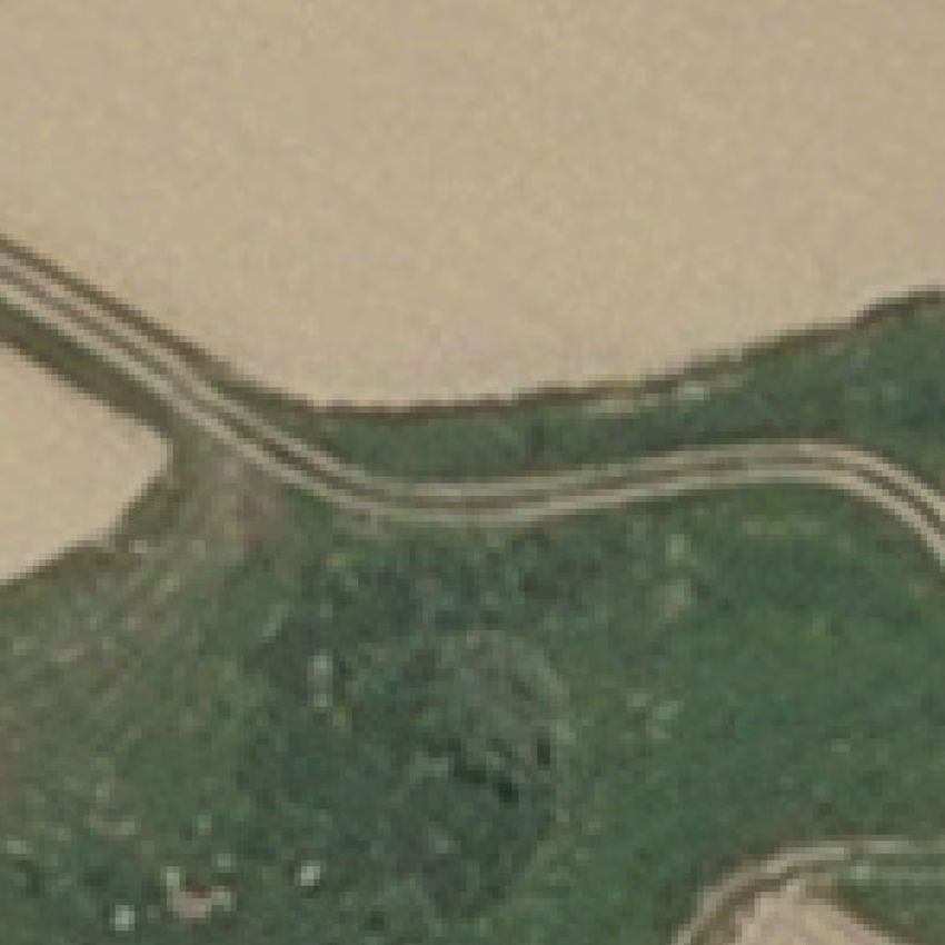
•   Attenuation Area 3 on the true right of the tributary: approximate area 2,500 m2
         •   Attenuation Area 4 on the true left of the tributary: approximate area
4.2 Re-Vegetation
It is anticipated that grass strike should take approximately 2-3 weeks after topsoil is replaced. Once
80% cover has been established, it will be deemed sufficient for erosion control. Silt fencing
downstream of the earthworks site, and up-gradient cut-off drains where applicable, shall remain in
place until such time.
As discussed above in section 3, grass species previously identified by local Iwi and Horizons as being
suitable for the region will be chosen.
4.3 Silt Fence
Prior to commencement of earthworks, silt fencing shall be installed at the base of each work area
along the sides of the watercourse of each geographically separate work site to retain any sediment.
Silt fencing at each work site shall remain in place until such time as re-vegetation cover has taken
hold sufficiently to manage erosion control.
The topography is relatively flat and has a grade ofFigure 4.1
Silt Fence Installation Detail
4.4 Scour Protection
As detailed in the project description, the site topography is generally very flat. In this regard, there
are no steep slopes or gradients within the watercourse that would require scour protection in the
form of Rip Rap, or similar.
4.5 Stabilised Construction Entrance
Site entrance will likely be via 128 Fairfield Rd for the majority of earthworks, for embankment #2
through to embankment #4, including attenuation areas between these embankments. Site of
crossing #1 may be accessed from property at 183 Roslyn Rd, while crossing #2 may be accessed from
property at 259 State Highway 57, Levin.
Page 8 V3 DRAFT FOR CONSENTINGA stabilised construction entrance shall be located at any point where traffic will be entering or leaving
the site, to prevent site access point(s) from becoming sediment sources, and to assist in minimising
dust generation and disturbance of areas adjacent to the road frontage.
The entrance shall be a stabilised pad of aggregate on a filter cloth base and is to be utilised with a
construction plan limiting traffic to this entrance(s) only. The entrance and/ or exit area shall be
cleared of all vegetation, roots and other undesirable material, and then constructed as per Figure 4.2
and Figure 4.3 below. Drainage shall be provided to carry runoff from the stabilised construction
entrance into an existing roadside drain where such is present.
Figure 4.2
Stabilised Construction Entrance Cross-Section
Figure 4.3
Stabilised Construction Entrance Plan View
4.6 Clean Water Cut-Offs
Site Areas for Crossing No. 1, No. 2 and 2nd Embankment are very small and do not require clean
water runoff diversions. Clean water cut-offs are proposed for the 3rd and 4th attenuation areas
including the associated excavation areas.
V3 DRAFT FOR CONSENTING Page 9Figure 4.4
Clean Water Cut-Off Drain
4.7 Sediment Retention Pond
A sediment retention pond is to be constructed at the downstream end of the Attenuation Area 3
earthworks area on the true left side of the tributary. The sediment retention pond shall be located
generally as shown in Appendix A in a position which is above the expected water level of the water
course during the earthworks period and to which runoff from within the majority of the earthworks
area can be directed.
The earthworks area which will be served by the sediment retention pond is approximately 5,000 m2
(noting that the upstream end of the earthworks area on true left side of the tributary will not be able
to be easily conveyed to the detention pond given the topography and narrow nature of the upstream
earthworks area. This portion of the earthworks will be controlled via perimeter cut-off drains and
sediment fencing). Therefore, as per the Sediment Retention Pond fact sheet and design guide
(Appendix B),
• a pond size of 100 m2 is required (being 2% of the catchment area). A 2.5:1 to 3:1 side ratio is
recommended, and therefore the pond should be nominally rectangle at 6 x 17 m (to give a ratio
of 2.8:1).
• A forebay of 10 m2 shall be provided in addition to above pond size (10% of the pond size). The
forebay is required to be across the full width of the pond (6m) and therefore should be 1.75 m
across to give a 10 m2 area. The forebay is to be between 0.5 and 1.0 m deep.
• A single T-bar decant is to be installed. This is sufficient to meet the design discharge rate (3
L/s/ha of contributing catchment, therefore a discharge rate of 1.5 L/s is required for the half
hectare catchment).
Sediment Retention Pond shall be constructed generally in accordance with Figures 4.5 to 4.7 below.
Page 10 V3 DRAFT FOR CONSENTINGFigure 4.5: Sediment Retention Pond Layout V3 DRAFT FOR CONSENTING Page 11
Figure 4.6: Decant Structure

Page 12                                  V3 DRAFT FOR CONSENTING
Figure 4.7: T-Bar Decant Detail

        Sediment capture levels in the sediment retention pond shall be checked weekly and sediment shall
        be cleared out if it reaches 30% of the pond volume.

5       MAINTENANCE, MONITORING AND REPORTING
        The erosion and sediment control systems will be inspected on a weekly basis prior to grass strike
        successfully occurring and within 24 hours of rainfall events where a heavy rain warning is issued by
        the New Zealand MetService. Damage to any ESC devices will be remedied after the rainfall event has
        ceased and the ground has drained sufficiently for vehicles access.

        If damage to any of the ESC devices occurs during the normal course of earthworks or other works on
        the site, the responsible party must report the damage to the Engineer to the Contract (or their
        representative) as soon as is practical. The damage will be inspected by the Engineer to the Contract
        (or their representative), whom will arrange for remedial work to be undertaken. If possible, all
        remedial work will be prioritised to be completed prior to the next rainfall event.

        This ESCP is considered a live document for the duration of the project. Should monitoring indicate
        that the measures outlined in this ESCP have proven to be insufficient, and require amendment or
        alteration at any stage, this ESCP will be updated, with the necessary changes implemented on site.

6       HEAVY RAINFALL RESPONSE AND CONTINGENCY MEASURES
        While earthworks are being undertaken it is the responsibility of the contractor to monitor weather
        forecasts. An inspection of all site ESCP devices shall be undertaken prior to the forecast event. If any
        ESCP device does not meet design standards, remedial work will be undertaken prior to the rainfall
        event, if at all possible.

V3 DRAFT FOR CONSENTING                                                                                 Page 13
7 SITE RESPONSIBILITIES
Individuals with responsibility for routine monitoring and maintenance, provision of design details for
ESC devices, and ensuring that ESC devices have been constructed correctly are detailed in the below
table.
Table 7.1
Site Responsibilities for Routine Monitoring and Maintenance
Role Responsibility Contact Number
Engineer to the Contract Monitoring of ESC Devices, weather forecasts, GHD Ltd
provision of design detail, ensure ESC devices Name and contact
constructed in line with design criteria, details to be confirmed
maintenance and documentation of ESCP.
Earthworks Contractor Monitoring of weather forecasts, construction of Higgins
ESC devices, report any damage to ESC devices, Project Manager name
remediation of ESC devices if required. and contact details to be
confirmed.
Page 14 V3 DRAFT FOR CONSENTINGAppendix A EROSION & SEDIMENT CONTROL PLANS
2nd Embankment

                                                                                                                                                                                  X
                                                                                                                       X

                                                                                                                                 X
       Upstream; To Crossing No. 1

                                                                                                                           X

                                                                             2nd ATTENUATION AREA

                                                                         No Attenuation to be created in this area

                                                                                                                                                                                                      Legend
                                                                                                                                                                                                         Embankment
                                                                                                                                                                                                           Culvert
                                                                                                                               Typical Embankment Details                                                  Current Channel
                                                                                                                                                                                                           Earthworks Extent
                                                                                                                           0         10            20       30                   40            50 m        Embankment Slope
                                                                                                                                                                                                           Silt Fencing
                                                                                                                                                  CLIENT
                                                            DRAWN                                                                                                Horowhenua District Council                   A1               ORIGINAL
                                                                                                                                                                                                       SCALE                    PROJECT
                                                                                                                                                  PROJECT
                                                           DESIGNED                                                                                          Koputaroa Stormwater Consen ng                    A3       1:250
                                                                                                                                                                                                                        1:350
                                                                                                                                                  TITLE
                                                           CHECKED                                                                1st ATTENUATION AREA                                                 PROJECT          27019     DATE
                                                                                                                                                                                                                    PROJECT
                                                           APPROVED
                                                                                                                                                                     Earthworks Stage 2                SHEET No
                                                                                                                                                                                                                                 ISSUED
                                                                                                                                                                    Second Embankment
REV.             AMENDMENTS          BY.   APPD.   DATE.              NAME     DATE                                                                                                                   REVISION No
Upstream; To 1st
ATTENUATION AREA
Crossing No. 1
X
Legend
Embankment
Culvert
Current Channel
Earthworks Extent
0 10 20 30 40 50 m Embankment Slope
Silt Fencing
CLIENT
DRAWN Horowhenua District Council A1 ORIGINAL
SCALE PROJECT
PROJECT
DESIGNED Koputaroa Stormwater Consen ng A3 1:350
TITLE
CHECKED PROJECT 27019 DATE
Earthworks Stage 2 PROJECT
ISSUED
APPROVED Crossing No. 1 SHEET No
REV. AMENDMENTS BY. APPD. DATE. NAME DATE REVISION NoCrossing No. 2
X
X
Legend
Embankment
Culvert
Current Channel
Earthworks Extent
0 10 20 30 40 50 m Embankment Slope
Silt Fencing
CLIENT
DRAWN Horowhenua District Council A1 ORIGINAL
SCALE PROJECT
PROJECT
DESIGNED Koputaroa Stormwater Consen ng A3 1:250
TITLE
CHECKED PROJECT 27019 DATE
PROJECT
Earthworks Stage 2 ISSUED
APPROVED SHEET No
Crossing No. 2
REV. AMENDMENTS BY. APPD. DATE. NAME DATE REVISION NoAppendix B FACTSHEETS REFERENCED BY HORIZONS REGIONAL COUNCIL
Earthworks series – erosion and sediment control factsheet

Sediment Retention Pond (SRP)

DEFINITION
A temporary pond formed by excavation into natural ground or by     Another major consideration is whether drainage works can be
the construction of an embankment, and incorporating a device to    routed to the sediment retention pond until such time as the site
dewater the pond at a rate that will allow suspended sediment to    is fully stabilised.
settle out.
                                                                    The general design approach is to create an impoundment of
                                                                    sufficient volume to capture a significant proportion of the design
PURPOSE                                                             run off event, and to provide quiescent (stilling) conditions, which
                                                                    promote the settling of suspended sediment.
To treat sediment-laden run off and reduce the volume of sediment
leaving a site, thus protecting downstream environments from        The sediment retention pond design is such that very large run
excessive sedimentation and water quality degradation.              off events will receive at least partial treatment and smaller run
                                                                    off events will receive a high level of treatment. To achieve this,
                                                                    the energy of the inlet water needs to be low to minimise re-
                                                                    suspension of sediment and the decant rate of the outlet also
APPLICATION
                                                                    needs to be low to minimise water currents and to allow sufficient
Sediment retention ponds are appropriate where treatment of         detention time for the suspended sediment to settle out.
sediment-laden run off is necessary, and are the appropriate
control measure for exposed catchments of more than 0.3ha. It       Specific design criteria are discussed below, but can be summarised
is vital that the sediment retention pond is maintained until the   as the following:
disturbed area is fully protected against erosion by permanent      • Use sediment retention ponds for bare areas of bulk earthworks
stabilisation.                                                        of 0.3ha or greater.
The location of the sediment retention pond needs to be carefully   • Restrict catchment areas to less than 5.0ha per sediment
considered in terms of the overall project, available room for        retention pond. This limits the length of overland flow paths and
construction and maintenance and the final location of any            reduces maintenance problems.
permanent stormwater retention facilities that may be constructed
at a later stage.

www.waikatoregion.govt.nz/earthworks
• Locate sediment retention ponds so
as to provide a convenient collection Typical silt pond layout
point for sediment laden flows from
the catchment area. This will require Bund/diversion drains to ensure
all flow enters at the inlet end
strategic use of cut-offs, run off diversion Wide shallow level spillway over existing ground where
possible, retain the existing grass cover. Bare areas to be
channels and contour drains. stabilised with concrete or similar
Secure the ends of the
level spreader by burying
• Locate sediment retention ponds to within the earth bund
allow access for removing sediment from
the pond.
• Locate sediment retention ponds to
allow the spillway to discharge over
undisturbed, well vegetated ground.
Floating
• Do not locate sediment retention ponds decants
within watercourses.
• Embankment and spillway stability are
generally the weak point in sediment
retention pond construction. Correct
compaction, particularly around
emergency spillways, discharge pipes All bare surfaces to be stabilised with vegetation if the pond is to
remain through a winter period, otherwise just the outer batter
and anti-seep collars, will keep the needs to be stabilised
system robust. Sediment
Forebay
Pinned geotextile overlaid with large rock to break up flow (1m deep)
Extra crest width may be required to
provide for machinery access for
cleaning out
Figure 1: Typical silt pond layout
DESIGN - SIZE OF THE POND
Calculate the volume of the sediment retention pond using the depth measured from
the base of the sediment retention pond to the top of the primary spillway. The following
design criteria apply:
• On earthwork sites with slopes less than 10 per cent and less than 200m in length,
construct a sediment retention pond with a minimum volume of 2 per cent of the
contributing catchment (200m3 for each ha of contributing catchment).
• On sites with slopes greater than 10 per cent and/or more than 200m in length,
construct sediment retention ponds with a minimum volume of 3 per cent of the
contributing catchment (300 m3 capacity for each ha of contributing catchment).
• An additional 10 per cent of this volume is to be used as a sediment forebay.
• The slope angle is determined by the steepest slope within a 50m radius of the
sediment retention pond inlet or by the average slope angle over the contributing
catchment, whichever is the greater.
• On sites that are particularly steep, have a high clay content or have sensitive
downstream environments, a greater sediment retention pond volume and/or the
use of chemical treatment may be required.
• Clean out sediment retention ponds when the volume of sediment accumulated
within them reaches 20 per cent of the design volume.
• Clearly show the sediment retention pond dimensions necessary to obtain the
required volume, as detailed above, on the site’s erosion and sediment control
plan(s).
2DESIGN - DEAD STORAGE (PERMANENT STORAGE) • If two decant systems are required,
Dead storage is the component of impoundment volume that does not decant and ensure the lower T-bar decant operates
remains in the sediment retention pond. It is important for dissipating the energy of through the full live storage depth of
inflows. the sediment retention pond. The upper
T-bar decant is to operate through the
• Ensure dead storage is a minimum of 30 per cent of the total sediment upper 50 per cent of the live storage
retention pond storage by positioning the lowest decant 0.54 - 0.8m above the depth of the sediment retention pond
invert of the sediment retention pond. only.
• If three decant systems are to be used,
DESIGN - LIVE STORAGE (DECANT STORAGE) then the lower T-bar decant operates
through the full live storage depth and
• Live storage is the volume between the lowest decant outlet level and the top
the second T-bar decant through the
of the sediment retention pond primary spillway.
upper two thirds of live storage depth of
• Ensure that the live storage volume capacity is 70 per cent of the total
the sediment retention pond. The upper
sediment retention pond storage.
T-bar decant operates through the upper
• The approved decant design detailed in these guidelines allows the decant
one third of live storage depth of the
system to be raised as sediment deposition increases, thereby maintaining the
sediment retention pond.
percentage volume of live storage.
• Ensure that the T-bar decant float is
securely fastened with steel strapping
directly on top of the decant arm,
and weight it to keep the decant arm
submerged just below the surface
through all stages of the decant cycle.
This will also minimise the potential for
blockage of the decant slots by floating
debris. The most successful method
found to date is to weight the decant
arm by strapping a 1.8m long waratah
between the float and the decant
(approximately 4kg of weight).
• Position the T-bar decant at the correct
height by supporting the decant arm
between warratahs as detailed in figure
2.
Sediment retention pond showing decant system. • Lay the discharge pipe at a 1 - 2 per
cent gradient, compact the fill material
around it using a machine compactor
DESIGN - DECANTING/OUTLET DE-WATERING DEVICE and incorporate anti-seep collars with
• De-water the sediment retention pond to remove the relatively clean water the following criteria:
without removing any of the settled sediment, and without removing any
• Install collars around the pipe
appreciable quantities of floating debris.
to increase the seepage length
• The use of a floating T-bar de-watering device, which allows for the decanting along the pipe with a spacing of
of the cleaner surface water from the top of the water column, is required. approximately 10m.
• The required decant rate from a sediment retention pond is 3 litres/second/ha • The vertical projection of each
of contributing catchment. This rate ensures that appropriate detention times collar is 1m.
are achieved.
• Ensure all anti seep collars and
• A standard T-bar design is detailed in figure 2 for various sized catchments. their connections are watertight.
Single decant without manhole riser needs to have a primary spillway (upstand
• Use a flexible thick rubber coupling
riser) installed.
to provide a connection between the
• To achieve a decant rate of 4.5 litres/second per decant, for a 1.5 ha catchment, decant arm and the primary spillway
drill 200 10mm diameter holes positioned evenly over the decant.Holes can be or discharge pipe. To provide sufficient
blocked as required for smaller catchments. Block out 65 holes if a decant rate flexibility (such as is required for the
of 3 l/sec is required. lower decant arm) install two couplings.
• T-bar decants must be able to operate through the full live storage depth of the Fasten the flexible coupling using strap
sediment retention pond. clamps and glue.
3• Where a concrete riser decant system is utilised, ensure the lower decant connection is positioned on an angle upwards from
the horizontal so as to split the operational angle that the decant works through. This will reduce the deformation force on the
coupling used.
T-Bar decant
Waratahs placed either side of decant arm as
alternative means of securing decant
Wire limiting vertical movement of decant
2m
2m
Standard Tee joint A Attach 1.8 long waratah to weight
300mm decant (see section A-A)
A Standard end caps
100mm diameter PVC pipe Decant Six equally spaced rows of
upstand with the top 10mm diameter holes at 60mm
positioned 150mm below Flexible rubber joints pacings along the full length of
the level of the emergency glued and clamped - two Wire or steel straps to the decant pipe
spillway. The treatment joints to be used only for joint decant and float
volume is to be measured lower decant
to the top of this upstand.
Single waratah fixed firmly
Section A-A
Float behind cable ties/straps
required to weight decant
Nylon cord to be tied Decant
through the end holes in
decant and secured to Standard waratah placement at
the waratah either end of the decant
Figure 2: T-Bar decant
DESIGN - FOREBAY
• Construct a forebay with a volume equal to 10 per cent • All inlets into the forebay are to be stabilised.
of the pond design volume. On sites with slopes less
• Access to the forebay is to be maintained at all times to
than 10 per cent and lengths less than 200m this equates
allow easy and frequent removal of accumulated sediments
to a forebay volume of 0.2 per cent of the contributing
by an excavator. Sediment should also be removed after
catchment area - 0.2 m3 per 100 m2 of contributing
every large storm event.
catchment. On sites with slopes greater than 10 per
cent and lengths greater than 200m, forebay volume is
equivalent to 0.3 per cent of the contributing catchment
area ie: 0.3 m3 per 100 m2 of contributing catchment.
• The forebay is to extend the full width of the main pond and
is to be 0.5 to 1m deep.
4DESIGN - EMBANKMENT
• Thoroughly compact the sediment
Single decant retention pond embankment, with
for catchments up to 1.5 hectares
material laid in 150mm layers and
Single decant
Width of top embankment should be for catchments up to 1.5 hectares
compacted to engineering standards.
wide enough to ensure machinery Minimum freeboard 300mm
access for de-sludging of pond, if there
are no other access points available
• Before building a sediment retention
Width of top embankment should be
wide enough to ensure machinery Minimum freeboard 300mm
SEE DECANT DETAIL pond, install sediment controls such
Spillway
access forcompacted
smoothed
are no othertoaccess
andof pond, if there
de-sludging
eliminate all available
points voids
Live as silt fences below the construction
storage
prior to laying and pinning
appropriate geotextile/concrete
SEE DECANT DETAIL variable
up to
area and maintain them to a functional
Spillway compacted and
smoothed to eliminate all voids
Pond battersand pinning
Live
1500mm
storage
standard until the sediment retention
prior to laying
2:1 to 3:1 geotextile/concrete
appropriate
variable
Dead
up to
storage
pond batters are fully stabilised.
1500mm
500mm
Pond batters
2:1 to 3:1 Pond base
Deadlevel
• Where possible, install the discharge
storage
500mm
pipes through the embankment as the
Poured concrete Poured concrete Waratah stakes
Pond base level
embankment is being constructed.
antiseep collar antiseep collar
2 x rubber couplingsWaratah
to provide
• Fully stabilise the external batter face by
Poured 100mmØ
concrete discharge pipe
Poured
laid concrete
at 1 stakes
antiseep collar
or 2% gradient. antiseep collar
additional range
vegetative or other means immediately
CROSS 2 x rubber couplings to provide after construction.
100mmØ discharge pipe laid SECTION
at 1
additional range
or 2% gradient.
• Ensure all bare areas associated with
Figure 3: Cross section of singleCROSS
decant
SECTION
Geotextile fabric should be laid
the sediment retention pond (including
Rip-rap placed at pond outlet with Waratahs and strong nylon
geotextile fabric placed underneath
into the pond to a depth of at
least 500mm below the
cord to control level of internal batters) are stabilised with
decant
spillway invert
Geotextile fabric should be laid Waratahs and strong nylon
vegetation if the sediment retention
Rip-rap placed at pond outlet with
geotextile fabric placed underneath
into the pond to a depth of at
least 500mm below the
cord to control level of
decant
pond is to remain in use over winter.
spillway invert
DESIGN - POND LEVEL
SPREADER
• Incorporate a pond level spreader between
the forebay and the main pond to spread
inflow velocities, thereby allowing rapid
dissipation of inflow energies. Combine
the pond level spreader with a well
Geotextile fabric secured firmly to
the embankment face. Anti-seep compacted and smoothed inlet batter (no
collars
steeper than a 3:1 gradient), stabilised
Geotextile fabric secured firmly to
the embankment face. Anti-seep
collars
over its entire area. The essential design
PLAN
TP90_11.dwg
feature is to ensure the pond level
spreader is completely level, non-erodible
PLAN
TP90_11.dwg
and spans the full width of the sediment
Figure 4: Plan view of decant retention pond.
• Stabilise the level spreader and inlet
embankment to the base of the pond
with a layer of strong woven low
permeability geotextile overlaid with a
DESIGN - SHAPE OF THE POND layer of soft non-woven needle punched
• Ensure the length to width ratio of the sediment retention pond is no less geotextile. Pin at 500mm centres.
than 3:1 and no greater than 5:1. The length of the sediment retention pond is • To ensure even inflows, install a trenched
measured as the distance between the inlet and the outlet (decant system). and pegged 150mm x 50mm timber weir
A 2:1 ratio may be used if the pond depth is no greater than 1m. or similar across the full width of the
• Maximise the distance between the inlet and the outlet (including the inlet. Bund the edges with compacted
emergency spillway) to reduce the risk of short circuiting and to promote earth to prevent outflanking and line
quiescent conditions. If this cannot be achieved by correctly positioning the to prevent erosion. This timber weir is
inlet and outlets, install baffles to achieve the appropriate length to width ratio haunched using site concrete which also
design. serves to toe in the geotextile protection
that will be required.
• Ensure that the sediment retention pond has a level spreader as described
in figure 5 to promote the even and gradual dissipation of the heavier inflow • Position the top of the pond level
water across the full area of the sediment retention pond. spreader weir 100 – 200mm above the
invert of the emergency spillway.
5/HYHOVSUHDGHU
PP[PP
(DUWK%XQGZLWK
VLWHFRQFUHWH
FRYHU
/HYHOVSUHDGHUIXOOZLGWKRILQOHWHQGVWDELOLVHGIURPWKHEHJLQQLQJRIWKHLQOHWWRWKH
SRQGLQYHUWZLWKOD\HUVRIJHRWH[WLOH
*HRWH[WLOH
:UDSSHGDURXQG /HYHOVSUHDGHU
OHYHOVSUHDGHUDQG &RQFUHWHKDXQFKLQJ
FRQFUHWHKDXQFKLQJ
LQOHWEDWWHUWREHVPRRWKHGDQGIUHHRI
YRLGV
)RUHED\ PGHHS
6HGLPHQW5HWHQWLRQ3RQG
[*HRWH[WLOH
OD\HUV
Figure 5: Pond level speader
OPTIONAL ENHANCEMENTS DESIGN - PRIMARY SPILLWAY
• Install one or more silt fences accross the width of the • For catchments up to 1.5ha use a discharge and primary
sediment retention pond. spillway pipe diameter of 100mm.
• Slope the base of the pond towards the inlet end. This will • For contributing catchments between 1.5 and 3ha in area,
reduce sediment travelling to the decant end of the pond. use a discharge and primary spillway pipe diameter of
150mm.
DESIGN - DEPTH OF POND • Where contributing catchments are 3ha or greater a
concrete manhole riser and a minimum 300mm diameter
• Sediment retention pond depths may be 1 - 2m deep, but
outlet pipe must be used as a primary spillway. The concrete
no deeper than 2m. Deeper ponds are more likely to cause
manhole riser must have a sealed bottom and be weighted
short circuiting problems during larger storm events and
to prevent floating.
require specifically designed floating decant systems.
• If the sediment retention pond is to operate over the
• The decant design in these guidelines operates through a
winter and the contributing catchment is fully stabilised,
maximum live storage range of 1.5m.
disconnect the T-bar decant to reduce the frequency of
emergency spillway activation and consequent erosion.
• Where a primary spillway upstand riser is used, place
the top of the riser a minimum 600mm lower than the
top of the sediment retention pond embankment and a
minimum 300mm lower than the emergency spillway crest.
Ensure the riser and the discharge pipe connections are all
completely watertight.
6SPILLWAY
• An emergency spillway is essential
for all sediment retention ponds.
• Emergency spillways must be
capable of accommodating the
critical 1 per cent AEP event without
eroding.
• Emergency spillways must discharge
onto stabilised ground. The
emergency spillway must be located
at the outlet end of the pond behind
or beside the decant system.
• The emergency spillway crest and
outer batter requires a very high
standard of stabilisation with the fill
material well compacted.
• Construct the emergency spillway as
a stabilised trapezoidal cross section.
The trapezoidal cross sections need
to be continued down the outside
batter to avoid flows outflanking the
geotextile.
• When utilising geotextile for
emergency spillway stabilisation
purposes, the batter face must be
smooth and all voids filled.
• If geotextile is used, a strong
woven low permeability geotextile
is laid first and then covered with Figure 6: Cross sections of plan SRP emergency spillway
a soft non-woven needle punched
geotextile. Ensure the geotextile is
pinned at 0.5m centres over the full
CONSTRUCTION SPECIFICATIONS
area of the emergency spillway. • Construct a fabric silt fence across the downslope end of the proposed works.
• Clear areas under proposed fills of topsoil or other unsuitable material down to
• Where possible, construct
competent material. Large fill embankments may need to be keyed in.
emergency spillways in well
vegetated, undisturbed ground (not • Use only approved fill.
fill) and discharge over long grass. • Place and compact fill in layers as per the engineer’s specifications.
• Construct the emergency spillway • Do not place pervious materials such as sand or gravel within the fill material.
with a minimum of 300 mm • Construct fill embankments approximately 10 per cent higher than the design
freeboard height above the primary height to allow for settlement of the material. Install appropriate pipe work and
spillway invert. anti-seep collars during the construction of the embankment and compact around
these appropriately.
• Install and stabilise the emergency spillway.
• Install and stabilise the level spreader.
• Securely attach the decant system to the horizontal pipework. Make all connections
watertight. Place any manhole riser on a firm foundation of impervious soil.
• Do not place pervious material such as sand or scoria around the discharge pipe or
the anti-seep collars.
• Check sediment retention pond freeboard for differential settlement and rectify as
necessary.
• Stabilise both internal and external batters with vegetation.
7POND MAINTENANCE AND DISPOSAL OF CHEMICAL TREATMENT
SEDIMENT Some chemicals can be used successfully to promote
• Clean out sediment retention ponds before the volume flocculation (clumping together) of suspended solids in the
of accumulated sediment reaches 20 per cent of the total sediment retention pond to increase the particle mass and
sediment retention pond volume. To assist in gauging speed the rate of settling:
sediment loads, clearly mark the 20 per cent volume height • Poly Aluminium Chloride (PAC)
on the decant riser. • poly-DADMAC
• Haloklear
• Clean out sediment retention ponds with high capacity • Crystalfloc
sludge pumps, or with excavators (long reach excavators if
needed) loading onto sealed tip trucks or to a secure area Chemical dosing systems are likely to be required where the
immediately adjacent to the pond. design sediment retention pond volume cannot be achieved
• The erosion and sediment control plan (ESCP) should because of site constraints and/or where a high level of
identify disposal locations for the sediment removed from treatment is required because of the sensitivity of the receiving
the sediment retention pond. Deposit the sediment in such environment. Chemical treatment is also more likely to be
a location so that it does not lead to a direct discharge required where the clay component is high or when specifically
to receiving environments. Stabilise all disposal sites as requested by council.
required and approved in the site’s ESCP.
All chemical treatments require flocculation mangement plans to
• Inspect sediment retention ponds a minimum of once per
be submitted and approved by Waikato Regional Council before
week and before every forecasted rainfall event. Inspect for
commencing any flocculation method.
correct operation after every run off event. Immediately
repair any damage to sediment retention ponds caused by
erosion or construction equipment.
SAFETY
Sediment retention ponds are attractive to children and can
become safety hazards if not appropriately fenced and if safety
rules are not followed. Low gradient pond batters provide an
additional safety measure. Check the safety requirements of the
city or district council authority and the Occupational Safety and
Health branch of the Department of Labour.
Waikato Regional Council For more information call Waikato Regional Council’s freephone on
Private Bag 3038 0800 800 401 or visit www.waikatoregion.govt.nz.
Waikato Mail Centre
Hamilton 3240 Waikato Regional Council earthworks factsheet series no. 2. December 2014 (4035)Earthworks series – erosion and sediment control factsheet
Silt fence
DEFINITION DESIGN
A temporary barrier of woven geotextile fabric used to intercept run • Ensure silt fence height is a minimum of 400mm above ground
off, reduce its velocity and impound sediment laden run off from level.
small areas of disturbed soil. • Place supporting posts/waratahs for silt fences no more than 2m
apart unless additional support is provided by tensioned wire
(2.5mm HT) along the top of the silt fence. Where a strong woven
PURPOSE
fabric is used in conjunction with a wire support, the distance
To detain flows from run off so that deposition of transported
between posts can be extended up to 4m. Double the silt fence
sediment can occur through settlement.
fabric over and fasten to the wire and posts with wire ties or
Silt fences can only be used to intercept sheet flow. Do not use silt cloth fastening clips at 150mm spacing. Ensure supporting posts/
fences as velocity checks in channels or place them where they will waratahs are embedded a minimum of 400mm into the ground.
intercept concentrated flow.
• Always install silt fences along the contour. Where this is not
possible or where there are long sections of silt fence, install
short silt fence returns, projecting upslope from the silt fence
APPLICATION to minimise concentrations of flows. Silt fence returns are a
• On low gradient sites or for confined areas where the contributing minimum of 2m in length, can incorporate a tie back and are
catchment is small, such as short steep batter fills and around generally constructed by continuing the silt fence around the
watercourses. return and doubling back to eliminate joins.
• To delineate the limit of disturbance on an earthworks site such • Join lengths of silt fence by doubling over fabric ends around
as riparian areas or bush reserves. a wooden post or batten or by stapling the fabric ends to a
batten and butting the two battens together as shown in figure 1
• To store run off behind the silt fence without damaging the fence
(overleaf).
or the submerged area behind the fence.
• Maximum slope lengths, spacing of returns and angles for silt
• Do not install silt fences across watercourses or in areas of
fences are shown in table 1 (overleaf).
concentrated flows.
• Install silt fence wings at either end of the silt fence projecting
upslope to a sufficient height to prevent outflanking.
www.waikatoregion.govt.nz/earthworks• Where impounded flow may overtop the MAINTENANCE
silt fence, crossing natural depressions or • Inspect silt fences at least once a week and after each rainfall. Make any necessary
low points, make provision for a riprap repairs when bulges occur or when sediment accumulation reaches 50 per cent of the
splash pad or other outlet protection fabric height.
device.
• Any areas of collapse, decomposition or ineffectiveness need to be immediately
• Do not use silt fences in catchments of replaced.
more than 0.25ha.
• Remove sediment deposits as necessary to continue to allow for adequate sediment
• Where water may pond behind the silt storage and reduce pressure on the silt fence. Ensure that the sediment is removed to a
fence, provide extra support with tie secure area.
backs from the silt fence to a central
stable point on the upward side. • Do not remove silt fence materials and sediment deposition until the catchment area
Extra support can also be provided by has been appropriately stabilised. Stabilise the area of the removed silt fence.
stringing wire between support stakes Table 1
and connecting the filter fabric to this
wire. Silt fence design criteria
Slope steepness (%) Slope length (m) Spacing of returns (m) Silt fence length (m)
(Maximum) (Maximum)
Flatter than 2% Unlimited N/A Unlimited
CONSTRUCTION 2-10% 40 60 300
SPECIFICATIONS 10-20% 30 50 230
• Use silt fence material appropriate to 20-33% 20 40 150
the site conditions and in accordance
33-50% 15 30 75
with the manufacturer’s specifications.
> 50% 6 20 40
• Excavate a trench a minimum of
100mm wide and 200mm deep along Figure 1 2m maximum
the proposed line of the silt fence.
Install the support posts on the
downslope edge of the trench and 400mm minimum
Ground level height of geotextile
silt fence fabric on the upslope side
200mm min Trench geotextile a
of the support posts to the full depth minimum of 200mm
into the ground
of the trench. Backfill the trench with
compacted soil. Steel standards such as waratahs or
standard wooden fencepost driven Flow Flow
a minimum of 400mm into the ground
• Use supporting posts of tanalised Elevation
timber a minimum of 50mm square, Geotextile fixed firmly
to post/waratah Overlap wooden battens
or steel waratahs at least 1.5m in length.
Flow 400mm minimum
height of geotextile
• Reinforce the top of the silt fence Staple Staple
Section B
fabric with a wire support made Compacted backfill 400mm minimum
post depth Section A
of galvanised wire of a minimum Trench geotextile 200mm
minimum into ground
Staple
diameter of 2.5mm. Tension the Staple
Cross section Standard fabric joint
wire using permanent wire strainers
attached to angled waratahs at the
end of the silt fence.
Where required returns a
minimum of 2 meters in Ends of returned
wired back to
• Where ends of silt fence fabric come length to reduce velocity
along the silt fence and stake or waratah
provide intermediate
together, ensure they are overlapped, impoundment
folded and stapled to prevent
sediment bypass. Provide leakproof joint at
the junction of the return
and main silt fence alignment
Perspective view
Waikato Regional Council For more information call Waikato Regional Council’s freephone on
Private Bag 3038 0800 800 401 or visit www.waikatoregion.govt.nz.
Waikato Mail Centre
Hamilton 3240 Waikato Regional Council earthworks factsheet series no. 1. February 2014 (3842)You can also read