En - Operating Manual AMAz
←
→
Page content transcription
If your browser does not render page correctly, please read the page content below

Operating Manual

                         AMAz
                     ISOBUS software for seed drills

                                               Please read this operating
MG5265                                     manual before commissioning.
BAG0143.12 03.20                          Keep it in a safe place for future
Printed in Germany
                                                                        use!

    en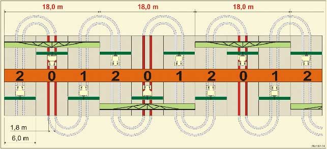
Reading the instruction
    manual and to adhere to it should not appear to
    be inconvenient and superfluous as it is not
    enough to hear from others and to realise that a
    machine is good, to buy it and to believe that now
    everything would work by itself. The person con-
    cerned would not only harm himself but also
    make the mistake of blaming the machine for the
    reason of a possible failure instead of himself. In
    order to ensure a good success one should go into
    the mind of a thing or make himself familiar with
    every part of the machine and to get acquainted
    with its handling. Only this way, you would be
    satisfied both with the machine as also with
    yourself. To achieve this is the purpose of this in-
    struction manual.

    Leipzig-Plagwitz 1872.

2                                  ISOBUS seed drill BAG0143.12 03.20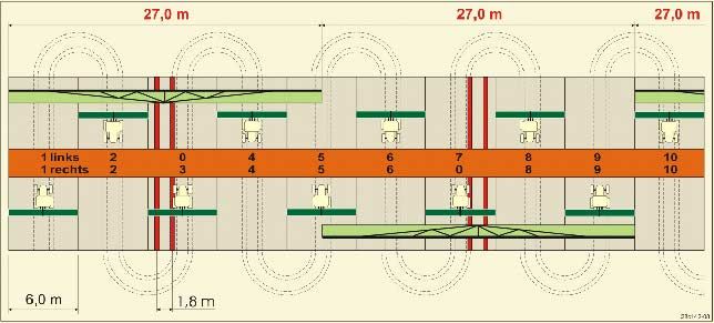
Identification data
Manufacturer's address
AMAZONEN-WERKE
H. DREYER GmbH & Co. KG
Postfach 51
D-49202 Hasbergen, Germany
Tel.: + 49 (0) 5405 50 1-0
E-mail: amazone@amazone.de
Spare part orders
Spare parts lists are freely accessible in the spare parts portal at
www.amazone.de.
Please send orders to your AMAZONE dealer.
Formalities of the operating manual
Document number: MG5265
Compilation date: 03.20
Copyright AMAZONEN-WERKE H. DREYER GmbH & Co. KG, 2020
All rights reserved.
Reprinting, even of sections, only possible with the approval of
AMAZONEN-WERKE H. DREYER GmbH & Co. KG.
ISOBUS seed drill BAG0143.12 03.20 3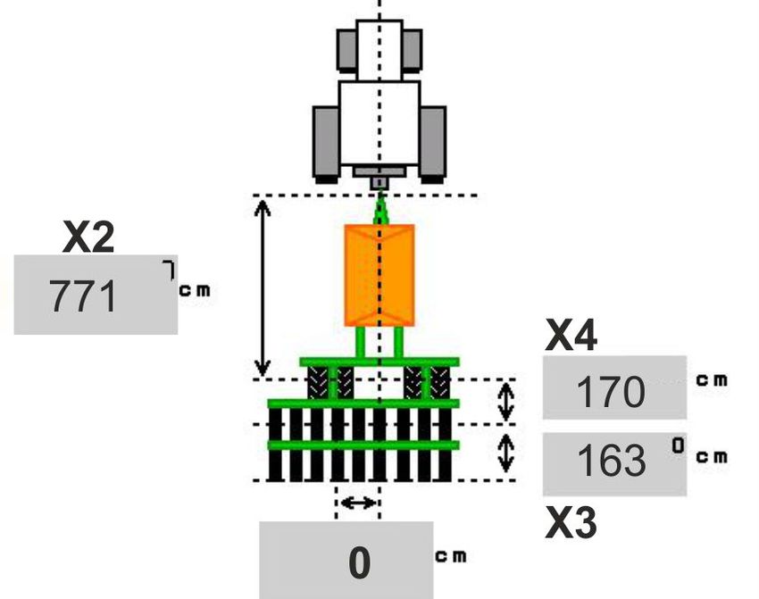
Foreword

Foreword

                  Dear Customer,
                  You have chosen one of the quality products from the wide product
                  range of AMAZONEN-WERKE, H. DREYER GmbH & Co. KG. We
                  thank you for your confidence in our products.
                  On receiving the implement, check to see if it has been damaged
                  during transport or if parts are missing. Using the delivery note, check
                  that the implement has been delivered in full, including any special
                  equipment ordered. Damage can only be rectified if problems are
                  signalled immediately.
                  Before commissioning, read and understand this operating manual,
                  and particularly the safety information. Only after careful reading will
                  you be able to benefit from the full scope of your newly purchased
                  implement.
                  Please ensure that all the implement operators have read this operat-
                  ing manual before they put the implement into operation.
                  Should you have any questions or problems, please consult this op-
                  erating manual or contact your local service partner.
                  Regular maintenance and timely replacement of worn or damaged
                  parts increases the lifespan of your implement.

User evaluation

                  Dear Reader
                  We update our operating manuals regularly. Your suggestions for
                  improvement help us to create ever more user-friendly manuals.

                  AMAZONEN-WERKE
                  H. DREYER GmbH & Co. KG
                  Postfach 51

                  D-49202 Hasbergen, Germany
                  Tel.:     + 49 (0) 5405 50 1-0
                  E-mail:   amazone@amazone.de

4                                                  ISOBUS seed drill BAG0143.12 03.20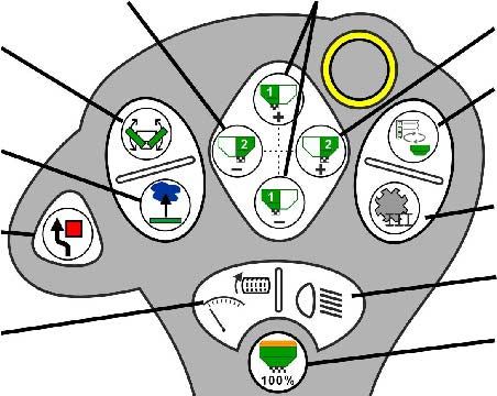
Table of Contents

1       User information .......................................................................................... 7
1.1     Purpose of the document ......................................................................................................... 7
1.2     Locations in the operating manual ........................................................................................... 7
1.3     Diagrams .................................................................................................................................. 7
2       General Safety Instructions ........................................................................ 8
2.1     Representation of safety symbols ............................................................................................ 8
3       Product description implement control software ..................................... 9
3.1     Software version ...................................................................................................................... 9
3.2     Menu navigation layout ............................................................................................................ 9
3.3     Hierarchy of the ISOBUS software ........................................................................................ 10
4       Main menu .................................................................................................. 11
4.1     Display of the Main menu ...................................................................................................... 11
4.2     Sub-menus of the Main menu ................................................................................................ 11
5       User profile ................................................................................................. 13
5.1     Configure multi-function display ............................................................................................. 15
5.2     Configure key assignment ..................................................................................................... 16
5.3     Configure ISOBUS ................................................................................................................. 17
5.3.1   Selecting the terminal ............................................................................................................ 17
5.4     Configure alarm limits ............................................................................................................ 18
5.5     Configuring the start-up ramp ................................................................................................ 19
6       Enter implement data ................................................................................ 20
6.1     Configuring the tramline ......................................................................................................... 21
6.1.1   Tramline rhythm ..................................................................................................................... 22
6.1.1   Table for seed rate reduction while creating tramlines .......................................................... 25
6.2     Configuring the working position ............................................................................................ 28
6.3     Configuring the speed source ................................................................................................ 29
6.4     Configure coulter pressure..................................................................................................... 30
6.5     Configuring the geometry....................................................................................................... 31
6.6     Configuring the antenna position ........................................................................................... 35
6.7     AutoPoint................................................................................................................................ 35
6.8     Pairing the Bluetooth device .................................................................................................. 37
7       Internal documentation ............................................................................. 38
8       Info menu.................................................................................................... 39
9       Calibration menu........................................................................................ 40
10      Product menu ............................................................................................. 42
10.1    Entering the setpoint application rate .................................................................................... 47
10.2    Configuring the blower fan speed .......................................................................................... 47
10.3    Configuring the delay time ..................................................................................................... 48
10.4    Configuring the fill level alarm ................................................................................................ 52
11      Hopper management ................................................................................. 53
11.1    Performing residual emptying ................................................................................................ 54
11.2    Refilling the hopper ................................................................................................................ 54
12      Use on the field – Work menu ................................................................... 55
12.1    Display in the Work menu ...................................................................................................... 56
12.2    Pre-selection for hydraulic functions ...................................................................................... 58
12.3    Deviations from the nominal state.......................................................................................... 59
12.4    Mini-view in Section Control................................................................................................... 59
ISOBUS seed drill BAG0143.12 03.20                                                                                                                 5
Table of Contents

12.5      Switching Section Control (GPS control) .............................................................................. 60
12.6      Track markers ....................................................................................................................... 61
12.7      Folding the implement ........................................................................................................... 62
12.8      Tramline control ..................................................................................................................... 64
12.8.1    Automatic tramline control ..................................................................................................... 65
12.9      Disc array working depth ....................................................................................................... 66
12.10     Coulter pressure via tractor control unit ................................................................................ 66
12.11     Coulter pressure in stages .................................................................................................... 66
12.12     Coulter lift .............................................................................................................................. 67
12.13     Electrical full metering ........................................................................................................... 68
12.14     Change in target quantity ...................................................................................................... 69
12.15     Change in the target quantity with divided hopper ................................................................ 69
12.16     Water hole function ............................................................................................................... 70
12.17     Alternative view hopper pressure .......................................................................................... 70
12.18     Recording mode for recording a field boundary .................................................................... 71
12.19     Boom part width sections ...................................................................................................... 71
12.20     Work lights ............................................................................................................................. 72
12.21     KG depth adjustment............................................................................................................. 72
12.22     Overview Multi-functional display ......................................................................................... 73
12.23     Procedure for use .................................................................................................................. 74
12.24     Driving on public roads .......................................................................................................... 74
13        TwinTerminal 3 .......................................................................................... 75
13.1      Product description................................................................................................................ 75
13.2      Performing a calibration ........................................................................................................ 77
13.3      Residual emptying ................................................................................................................. 80
14        AUX-N multi-function sticks ..................................................................... 81
15        AmaPilot/AmaPilot+ multi-function stick ................................................ 83
16        Fault............................................................................................................ 85
16.1      Display on the control terminal .............................................................................................. 85
16.2      Fault table .............................................................................................................................. 86
16.3      Failure of functions without alarm message on the terminal ................................................. 91
16.4      Failure of the speed signal from the ISOBUS ....................................................................... 91

6                                                                                          ISOBUS seed drill BAG0143.12 03.20
User information

1        User information
                             The User Information section provides information on use of the oper-
                             ating manual.

1.1     Purpose of the document

                             This operating manual
                             •    describes the operation and maintenance of the implement.
                             •    provides important information on safe and efficient handling of
                                  the implement.
                             •    is a component part of the implement and should always be kept
                                  with the implement or the towing vehicle.
                             •    must be kept in a safe place for future use.

1.2     Locations in the operating manual

                             All the directions specified in the operating manual are always seen in
                             the direction of travel.

1.3     Diagrams

Instructions and responses

                             Activities to be carried out by the user are given as numbered instruc-
                             tions. Always keep to the order of the instructions. The reaction to the
                             handling instructions is given by an arrow.
                             Example:
                              1. Instruction 1
                             → Implement response to instruction 1
                              2. Instruction 2

Lists

                             Lists without an essential order are shown as a list with bullets.
                             Example:
                             •    Point 1
                             •    Point 2

Item numbers in diagrams

                             Numbers in round brackets refer to the item numbers in the diagrams.
                             Example:
                             (1) Position 1

ISOBUS seed drill BAG0143.12 03.20                                                                   7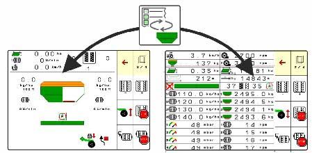
General Safety Instructions

2         General Safety Instructions
                              Knowledge of the basic safety information and safety regulations is a
                              basic requirement for safe handling and fault-free implement opera-
                              tion.

                              The operating manual
                              •    must always be kept at the place at which the implement is op-
                                   erated.
                              •    must always be easily accessible for the user and maintenance
                                   personnel.

2.1       Representation of safety symbols

                              Safety instructions are indicated by the triangular safety symbol and
                              the highlighted signal word. The signal word (danger, warning, cau-
                              tion) describes the severity of the risk, and carries the following mean-
                              ing:

                              DANGER
                              Indicates an immediate high risk which will result in death or
                              serious physical injury (loss of body parts or long term damage)
                              if not avoided.
                              If the instructions are not followed, then this will result in imme-
                              diate death or serious physical injury.

                              WARNING
                              Indicates a medium risk, which could result in death or (serious)
                              physical injury if not avoided.
                              If the instructions are not followed, then this may result in death
                              or serious physical injury.

                              CAUTION
                              Indicates a low risk which could cause minor or medium level
                              physical injury or damage to property if not avoided.

                              IMPORTANT
                              Indicates an obligation to special behaviour or an activity re-
                              quired for proper implement handling.
                              Non-compliance with these instructions can cause faults on the
                              implement or disturbance to the environment.

                              NOTE
                              Indicates handling tips and particularly useful information.
                              These instructions will help you to use all the functions of your
                              implement in the best way possible.

8                                                             ISOBUS seed drill BAG0143.12 03.20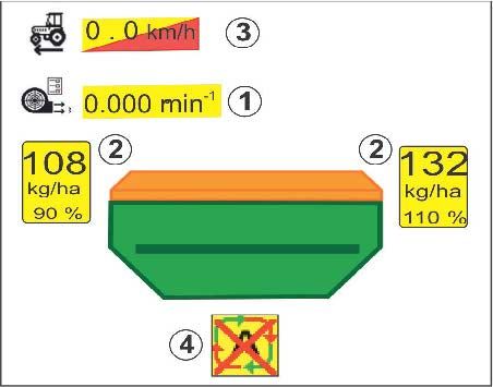
Product description implement control software

3       Product description implement control software
                           The ISOBUS software and an ISOBUS terminal make it easy to con-
                           trol, operate and monitor the AMAZONE implements.
                           The ISOBUS software works with the following AMAZONE seed drills:
                           •   Cirrus 03
                           •   Cayena
                           •   Condor
                           •   Citan
                           •   XTender
                           •   AD-P
                           •   Primera DMC
                           The Main menu is shown after switching on the ISOBUS terminal
                           when the implement computer is connected.
                           Settings
                           The settings can be adjusted through the sub-menus in the Main
                           menu.
                           Use
                           The ISOBUS software controls the application rate according to for-
                           ward speed.
                           The Work menu shows all of the work data during operation and,
                           depending on the equipment, the implement can be operated through
                           the Work menu.

3.1     Software version

                           This operating manual is valid from software version:
                           Base computer             8.08.01

                           A message is displayed if a component (computer / control unit) does
                           not have the current software.
                           It is still possible to work with the implement temporarily.
                           →     Perform an update of the respective software in the near future.

3.2     Menu navigation layout

                                     Function fields with white background
                           →     For executing functions

                                  Function fields with coloured background
                           →     For menu navigation

                           •            Back to the previous menu

                           •             Scrolling in the menu

ISOBUS seed drill BAG0143.12 03.20                                                                  9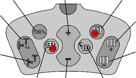
Product description implement control software
3.3 Hierarchy of the ISOBUS software
Main menu Work menu
Product menu Internal documentation
• Deactivate the hopper •
• Change hoppers
• Switch to TwinTerminal •
___________________________________________
• Product name
• Setpoint application rate •
Filling / emptying
• Metering roller
• Calibration area •
• Determining the calibration factor
• Configuring the blower fan speed
• Calibration factor
• Configure on/off point delays
• Fill level alarm
• Filling
User profile menu Calibration
• Enter the name of the user
• Configure key assignment
• Configure the multi-functional display in the
Work menu
• Configure alarm limits
• Configure the application rate increments for
increasing or reducing the application rate Info menu
• Configure the start-up ramp
• Configure ISOBUS • Display implement ID No. (MIN)
• Switch the work lights • Display work rate
• Reverse driving detection • Display the computers and software
• Driver assistance system
Implement settings menu
• Configure tramline
• Configure the working position sensor
• Configure the source for the speed signal
• Time for pre-metering
• Configure coulter pressure
• Fill level alarm
• Water hole• Recording mode
• Configure the geometry
• Configure antenna position• AutoPoint
• Setup
10 ISOBUS seed drill BAG0143.12 03.20Main menu
4 Main menu
4.1 Display of the Main menu
(1) Display and settings
(2) Function fields for sub-menus
1 2
• Adjusted implement Cirrus
Speed band
• Minimum and maximum working speed
min max
8.0km/h 13.0km/h
• Application rate for
Hopper 1 Deactivated
ο Hopper 1 Cereals I
kg/ha
ο Other hoppers (optional)
Hopper 2 Cereals 2
→ Changes are also possible here. Values will
be adopted in the product menu kg/ha
Shows that an external job has
been started.
Deactivated Shows deactivated hopper(s).
4.2 Sub-menus of the Main menu
Menus for working with the implement
• Work menu
ο Display and controls during operation.
• Hopper management
ο Filling / emptying the hopper
• Determining the calibration factor (also in the Products
menu)
ISOBUS seed drill BAG0143.12 03.20 11Main menu
Menus for settings, information about the implement and seed
• Product menu
ο Settings for the seed
• User profile menu
ο Each user can save a personal profile with settings for the
terminal and the implement.
• Implement settings menu
ο Entry of implement-specific or individual data.
ο Change the setup of the implement (password required)
• Documentation menu (as a simple alternative to the Task
Controller)
ο Saving of areas, times, quantity.
ο The calculated data can be stored for up to 20 documented
jobs.
• Info menu
ο Software version and total ground coverage
12 ISOBUS seed drill BAG0143.12 03.20User profile
5 User profile
Select User profile in the main menu!
User profile
• Enter the name of the user
• Configure the multi-function display in the Configure multi-function
Work menu (see page 15) display
• Configure key assignment
Configure key assignment
(see page 16)
• Configure ISOBUS (see page 17)
Configure ISOBUS
• Configure alarm limits (see page 15) Configure
alarm limit
• Enter the application rate increments for
Quantity increment %
increasing or reducing the application rate
• Configure the start-up ramp (see page 19) Configuring the start-up
ramp
• Switching of the work lights
can be controlled manually or by the TECU.
ο The TECU switches the work lights Work lights
on as soon as the work lights are via TECU
switched on in the tractor.
ο Switch the work lights manually.
• Reverse driving detection
ο (yes) When driving in reverse, the
metering unit and the advancing of the Reverse driving detection
tramline is interrupted (ISOBUS signal
must be present).
ο (no)
• Driver assistance system
ο (yes) Show notification when the
forward speed was strongly changed Driver assistance system
on the headland, so that a seeding er-
ror is produced.
ο (no) No notification
ISOBUS seed drill BAG0143.12 03.20 13User profile
User: change, new, delete
Change user:
Profile list
1. Mark user.
2. Confirm marking.
Pit
Create new user:
Tom
1. Create new user.
2. Mark user.
3. Confirm marking.
4. Enter name.
The terminal must be restarted after chang-
ing users
Delete user:
Mark symbol and confirm.
When using an AUX-N multi-function stick, the freely selected key
assignment of the multi-function stick are saved with the respective
user.
Each user profile needs a key assignment.
Perform the key assignment on the VT.
14 ISOBUS seed drill BAG0143.12 03.20User profile
5.1 Configure multi-function display
Different data sets can be shown in the three
data lines in the Work menu.
(1) Current speed
(2) Worked area per day
(3) Quantity per day
(4) Remaining area
(5) Distance remaining
(6) Distance counter
(7) Speed of metering unit 1
Configure
(8) Speed of metering unit 2 multi-function display
Line 1
(9) Speed of metering unit 3
Speed
(10) Speed of metering unit 4
(11) Setpoint for metering unit 1 Line 2
(12) Setpoint for metering unit 2 Area / Day
(13) Setpoint for metering unit 3
Line 3
(14) Setpoint for metering unit 4 Distance remain.
(15) Pressure in hopper 1
(16) Pressure in hopper 2
(17) Distance remaining
(18) Blower fan actual speed 1
(19) Blower fan actual speed 4
(20) Residual quantity in hopper 1
(21) Residual quantity in hopper 2
(22) Residual quantity in hopper 3
(23) Residual quantity in hopper 4
ISOBUS seed drill BAG0143.12 03.20 15User profile
5.2 Configure key assignment
Here the function fields of the work menu can be
Configure
freely assigned.
key assignment
• Free key assignment
ο Freely assignable key assignment
ο Standard assignment of the keys Free key
assignment
s
• Load standard joystick button assignment Load standard joystick button
assignment
• Freely assign the buttons Select the desired function
from the list and press
the desired button.
→ Call up list of the function Empty /
delete function
Cancel Save
Perform key assignment: List of the functions:
1. Call up list of the functions. Function 1
2. Select function.
Function 2
3. If applicable, select the screen where
the function should be saved in the work Function 3
menu.
4. Press the key / function field in order to Function 4
place the function to the key / function firled.
5. In this manner, all functions can be as- Function 5
signed any way you like.
…
6. Save the settings or
cancel.
• Function field without function.
16 ISOBUS seed drill BAG0143.12 03.20User profile
5.3 Configure ISOBUS
Configure
ISOBUS
• Select the terminal (see page 17)
Select terminal
• Documentation Documentation
ο TaskController, task management ac-
tive
→ Implement computers communicate
with the Task Controller of the terminal
ο implement-internal documentation
Seed drill implement description
• Seed drill implement description Seed drill
implement description
ο Multi bin (multiple hoppers)
ο Multi boom (multiple seeding rails)
• Switching Section Control between manual Section Control
/ automatic Switching Manu-
al/Automatic
ο In the GPS menu
Section Control is switched in the GPS
menu.
ο In the work menu (recommended set-
ting)
Section Control is switched in the work
menu of the implement software.
5.3.1 Selecting the terminal
If several terminals are connected to the
Select terminal
ISOBUS:
• Select the terminal for implement operation Terminal for implement oper-
ation
from the list of terminals.
ο 01 Amazone
ο 02 Third-party supplier
• Select the terminal for documentation from Terminal for documentation
the list of terminals. and Section Control
ο 01 Amazone
ο 02 Third-party supplier
Logging onto the UT terminal can take
Cancel Change
up to 40 seconds.
If the specified terminal is not found
after this time, the implement logs onto
another terminal.
ISOBUS seed drill BAG0143.12 03.20 17User profile
5.4 Configure alarm limits
Configure
alarm limits
• Enter the alarm limit for the blower fan Blower fan alarm limit %
speed in %.
→ A signal sounds when exceeding the alarm
limit during operation. Minimum press Bar
Default value: 15%
Maximum press Bar
• Enter the minimum air pressure in the hop-
per.
• Enter the maximum air pressure in the hop-
per.
→ A warning message appears when outside
the entered pressure range.
→ Pressurised hopper monitoring must be
active.
18 ISOBUS seed drill BAG0143.12 03.20User profile
5.5 Configuring the start-up ramp
The start-up ramp prevents under metering when
starting up.
When beginning work, the metering is applied
according to the simulated start-up speed until
the specified time expires. After that, the speed-
dependent rate control is regulated.
Once the speed entered has been reached or
exceeds the simulated speed, the quantity regu-
lation starts.
• Intended speed, working speed in km/h.
Configure start-up
Default value: 12 km/h ramp
• Start-up ramp on /off
Intended
ο on km/h
speed
ο off
• Ramp start speed as a %-value of the in- Start-up ramp
tended speed at which the metering starts.
Default value: 50%
Ramp start speed %
• Time that passes until the simulated speed
is actually reached in seconds.
Default value: 5 s Duration start-up ramp s
ISOBUS seed drill BAG0143.12 03.20 19Enter implement data
6 Enter implement data
In the main menu, select Implement data!
Maschineneinstellungen
• Configure the tramline (see page 21) Configure
tramline
• Configure the working position sensor (see Configuring the working
page 28) position sensor
• Configure source for the speed signal (see Configuring the speed
page 29) source
• Time for pre-metering
Time for
→ Default value: 3 s S
pre-metering
• Configure coulter pressure (see page 52)
Configure coulter pressure
• Display the residual quantity in the work
menu Display the residual
ο on quantity in the work %
menu
ο off
• On / off selection for water hole function in
the work menu
ο on
ο off
• Recording mode for recording the field
boundary on / off
ο on (Function field for recording
shown in the work menu)
ο off
• Configure the geometry (see page 31)
Configure the
geometry
• Configure the antenna position (see page
35) Configure antenna position
• Configure AutoPoint (see page 21)
AutoPoint
• Call up the setup menu (only for customer
service) Setup
• Pairing the Bluetooth device, see page 37
Pair Bluetooth device
20 ISOBUS seed drill BAG0143.12 03.20Enter implement data
6.1 Configuring the tramline
Configure
tramline
• Enter the tramline rhythm see page 22
Tramline rhythm
• Enter the seed rate reduction for creating
tramlines Seed rate reduction
at tramline
• Interval tramline
ο (yes) Interval tramline
ο (no)
• For interval tramline: Enter the length of the
seeded distance Seeded distance
• For interval tramline: Enter the length of the
non-seeded distance
Non-seeded distance
• The tramlines are advanced by means of
the:
ο Working positionο
ο Track marker
Source for advancing the
Switch the tramlines automatically (see tramline
page 65).
ο Terminal CCI
ο ISOBUS
• Enter time until tramline is advanced Time until the tramline is
advanced
s
ISOBUS seed drill BAG0143.12 03.20 21Enter implement data
6.1.1 Tramline rhythm
Example of simple tramline
control, standard tramline
Tramline counter:
Special tramline rhythms:
• 0 – Permanent tramline
• 1 - Alternating tramline
• 15 – No tramline
Simple - Tramline control
1 2 3 4 5 6 7 8 9 10 11 12 13 14 15 16 17 20 21 22 23 26 32 35
0 0 0 0 0 0 0 0 0 1 1 0 0 0 1 0 0 0 0 0 0 0 0 0
1 0 1 1 1 1 1 1 1 2 0 1 1 1 1 1 1 0 0 0 1 0 1
1 2 2 2 2 2 2 2 3 3 2 2 2 2 2 2 1 1 1 2 1 2
2 3 3 3 3 3 3 0 4 3 3 3 3 3 3 2 2 2 3 2 3
4 4 4 4 4 5 5 4 4 4 4 4 4 3 3 3 4 3 4
Circuit 15 does not create channels.
5 5 5 5 6 6 5 5 5 5 5 5 4 4 4 5 4 5
Tramline counter
6 6 6 0 7 6 6 6 6 6 6 5 5 6 5 6
7 7 8 8 7 7 7 7 7 7 6 6 7 6 7
8 9 0 8 8 8 8 8 8 7 8 7 8
10 10 9 9 9 9 9 9 8 9 8 9
10 10 10 10 10 10 9 10
11 11 11 11 11 10 11
12 12 12 12 12
13 13 13 13
14 14 14
15 15
16
22 ISOBUS seed drill BAG0143.12 03.20Enter implement data
Example of double tramline
control, requires 2 seed dis-
tributors
Tramline counter, left side:
Tramline counter, right side:
Double - Tramline control
19 right side
18 right side
24 right side
25 right side
27 right side
28 right side
29 right side
30 right side
31 right side
33 right side
34 right side
36 right side
18 left side
19 left side
24 left side
25 left side
29 left side
30 left side
31 left side
33 left side
34 left side
36 left side
27 left side
28 left side
1 1 1 1 1 1 1 1 1 1 1 0 1 1 1 1 1 1 1 1 1 1 1 1
2 2 2 2 2 0 2 0 2 0 2 2 2 0 0 2 2 2 2 2 2 2 2 2
0 3 3 0 3 3 3 3 3 3 0 3 3 3 0 3 3 3 3 3 3 0
4 4 4 4 0 4 4 4 4 4 0 4 4 4 4 4 4 4 4 4 4 4
5 5 5 5 5 5 5 5 0 5 5 5 5 0 0 5 5 5 5 5
6 6 6 6 6 6 0 6 0 6 6 0 6 6 6 6 0 6 6 6
7 0 0 7 0 7 7 7 7 7 7 7 7 7 0 7
8 8 8 8 8 8 8 8 8 8 8 8 8 8 0 8
Tramline counter
9 9 9 9 9 0 0 9 9 0 9 9 9 9 9 9
10 10 10 10 10 10 10 10 10 10 10 0 10 10 10 10
11 11 11 11 11 11 0 11 11 11
12 0 0 12 12 12 12 12 12 0
13 13 13 13 13 0 13 13 13 13
14 14 14 14 14 14 14 14 14 14
15 15 15 15 15 15
0 16 16 0 16 16
17 17 17 17 17 0
18 18 18 18 18 18
19 19
20 20
21 21
22 0
ISOBUS seed drill BAG0143.12 03.20 23Enter implement data
Double - Tramline control
38 right
37 right
39 right
40 right
41 right
42 right
43 right
44 right
45 right
46 right
37 left
38 left
39 left
43 left
44 left
45 left
41 left
42 left
40left
46left
1 0 1 1 1 1 1 1 1 1 1 1 1 1 0 1 1 1 1 1
2 2 2 0 0 2 2 2 2 2 2 2 2 0 0 2 2 2 2 2
0 3 3 3 0 3 3 3 3 0 3 3 3 3 3 3 3 3 3 3
0 4 0 4 4 4 4 0 4 4 4 0 4 4 4 4 0 4 4 0
5 5 0 5 5 5 5 5 5 5 5 5 5 5 5 5 5 5
6 0 6 6 6 6 6 6 6 6 0 6 6 0 6 6 6 6
7 0 7 7 7 7 7 7 7 7 7 0 7 7 7 7
8 8 8 8 8 8 8 8 8 8 8 8 8 8 8 8
9 9 0 9 9 9 0 9 9 9 9 9 9 9
0 10 10 10 0 10 10 10 10 10 10 10 10 10
Tramline counter
0 11 11 11 11 11 11 11 11 11 11 11
12 12 12 12 12 12 12 12 12 0 0 12
13 13 13 13 13 13 13 0 13 13 13 13
14 14 14 0 14 14 14 14 14 14 14 14
15 15 15 15 15 15 15 15 15 15
16 16 16 16 16 16 16 16 16 16
17 0 17 17 0 17 17 17 17 17
18 18 18 18 18 18 18 18 18 18
19 19 19 19 19 19 19 0 19 0
20 20 0 20 20 20 20 20 20 20
21 21 21 21 21 21 21 21
22 22 22 22 22 22 22 22
23 23 23 23 23 23
24 24 24 24 24 24
25 25 25 25 25 25
26 26 26 26 26 26
0 27 0 27
28 28 28 28
29 29 29 29
30 30 30 30
24 ISOBUS seed drill BAG0143.12 03.20Enter implement data
6.1.1 Table for seed rate reduction while creating tramlines
Calculation of the seed rate reduction as follows:
100 x number of tramline hoses
=
Number of seeding coulters
Number of seeding coul- Number of
Working width
ters tramline hoses Recommended percent-
age seed rate reduction
while creating
tramlines
18 4 22%
18 6 33%
18 8 44%
20 4 20%
20 6 30%
20 8 40%
3,0 m
20 10 50%
24 4 17%
24 6 25%
24 8 33%
24 10 42%
24 12 50%
21 4 19%
21 6 29%
21 8 38%
21 10 48%
24 4 17%
24 6 25%
24 8 33%
3,43 m / 3,5 m
24 10 42%
24 12 50%
28 4 14%
28 6 21%
28 8 29%
28 10 36%
28 12 43%
ISOBUS seed drill BAG0143.12 03.20 25Enter implement data
Number of seeding coul- Number of
Working width
ters tramline hoses Recommended percent-
age seed rate reduction
while creating
tramlines
24 4 17%
24 6 25%
24 8 33%
24 10 42%
24 12 50%
26 4 15%
4,0 m 26 6 23%
26 8 31%
26 10 38%
26 12 46%
32 4 13%
32 6 19%
32 8 25%
27 4 15%
27 6 22%
27 8 30%
4,5
36 4 11%
36 6 17%
36 8 22%
40 4 10%
5,0 m 40 6 15%
40 8 20%
36 4 11%
36 6 16%
36 8 22%
36 10 28%
36 12 33%
6,0 m
48 4 8%
48 6 12%
48 8 17%
48 10 21%
48 12 25%
26 ISOBUS seed drill BAG0143.12 03.20Enter implement data
Number of seeding coul- Number of
Working width
ters tramline hoses Recommended percent-
age seed rate reduction
while creating
tramlines
64 4 6%
8,0 m 64 6 9%
64 8 12%
72 4 6%
9,0 m 72 6 8%
72 8 11%
36 4 11%
36 6 17%
48 4 8%
48 6 13%
72 4 6%
72 6 8%
12,0 m 72 8 11%
72 10 14%
96 4 4%
96 6 6%
96 8 8%
96 10 10%
96 12 13%
48 4 8%
48 6 13%
60 4 7%
60 6 10%
15,0 m
90 4 4%
90 6 7%
90 8 9%
90 10 11%
On implements with seed quantity return flow: set seed quantity re-
duction at 0 %.
ISOBUS seed drill BAG0143.12 03.20 27Enter implement data
6.2 Configuring the working position
Configuring the working
position sensor
• Source Source
working
ο Sensor (implement) in volts position sensor
ο Lifting height ISOBUS in %
ο Lifting height ISOBUS digital Stored
0.50 -4.50 V
range of values
• Teaching in switch points (see page 28)
Learn limit values
• Changing switch points (see page 28)
Change switch points
Learn limit values
When teaching in the switch points, a lifting
height of the implement is assigned to a switch Learn limit values 1/6
point using the working position sensor.
1. Completely lower the implement. Please lower the implement
completely.
2. > Continue
Current value 0.00 V
3. Completely raise the implement.
4. Save the calculated values.
Cancel Continue
Cirrus with TwinTec: Perform after each
adjustment of the working depth
Change switch points
Change switch points
• Metering unit off switch point Switch point
%
metering off
• Metering unit on switch point
Switch point
• Headlands position switch point (optional) metering on
%
• Folding position switch point (optional)
Switch point
%
headlands position
Switch point
%
folding position
28 ISOBUS seed drill BAG0143.12 03.20Enter implement data
6.3 Configuring the speed source
The implement computer needs a speed signal for a correct rate con-
trol.
There are different sources for the forward speed signal input.
• The speed signal can be provided via the ISOBUS.
• The speed signal can be calculated using the pulses per 100 m.
• The speed signal is simulated by entering a speed (e.g., when a
speed signal from the tractor fails).
Entering a simulated speed allows you to continue operation
even if the speed signal fails.
• Select the source of the speed signal. Configure
speed
ο Radar (ISOBUS) source
ο Wheel (ISOBUS) Speed
source
ο Satellite (NMEA 2000)
ο Satellite (J1939)
ο Radar (implement)
ο Simulated Wheel imp.
Pulse /
→ Speed entered must be observed 100 m
later in all cases
→ If another speed source is detected, Find impulses
the simulated speed is deactivated au-
tomatically.
Check the accuracy of the utilised speed
source
→ Inaccurate speed sources can cause seed-
ing errors.
• Enter value for pulses per 100 m,
Default value: 9700 (for wheel sensor)
or
• Determine pulses per 100 m
ISOBUS seed drill BAG0143.12 03.20 29Enter implement data
Determine the speed on the implement via the wheel pulse per 100 m
You must determine the wheel pulses per 100 m in working position
under the prevailing operating conditions.
1. On the field, measure out a calibration dis-
Find impulses 1/4
tance of exactly 100 m.
2. Mark the start and end points. Measure out the
100 m
distance exactly
3. > continue
4. Move the tractor to the start position.
5. > continue Driven impulses 0
6. Accurately travel along the measurement
section from start to finish. 500
→ The pulses are detected continuously and
shown on the display.
Cancel Continue
7. Stop exactly at the end point.
8. → Save
6.4 Configure coulter pressure
The coulter pressure is gradually configured. A Configure coulter pressure
seed rate increase can be selected accordingly if
a coulter pressure is present.
• Increase of the seed rate with coulter pres-
sure from stage 0 to 10. Increase of the seed
rate starting at stage
(default value 5)
• Increase of the seed rate per coulter pres-
sure stage in %. Increase of the seed
%
rate per stage
(default value 10%)
• Minimum coulter pressure Minimum coulter pres-
(standard value 0) sure
• Maximum coulter pressure Maximum coulter
(standard value 10) pressure
• Control the setting of the coulter pressure
via the Task Controller.
Coulter pressure via
ο yes Task Controller
ο no
• Assign the output value 100% from the
Task Controller to a coulter pressure level. Output value equals
the level 100%
(default value 5)
30 ISOBUS seed drill BAG0143.12 03.20Enter implement data
6.5 Configuring the geometry
• The data are pre-configured depending on the type of the im-
plement and must normally not be changed.
• The geometry data must match with the real length dimensions
of the implement.
Lateral offset - implement to the left: Enter negative value
Geometry data for mounted implements
Configure
geometry
X1 [cm]
Machine
min max
303 Special WS 224 236
303 Special RoteC 210 221
353 Special 224 236
AD-P
403 Special 210 221
303 Super RoteC 205 209
303 Super RoteC+ 217 221
403 Super RoteC 205 209
403 Super RoteC+ 217 221
ISOBUS seed drill BAG0143.12 03.20 31Enter implement data
Geometry data for towed implements
Cirrus
Machine X2 [cm] X3 [cm]
min max
3003 442 552
3003 compact 442 552
3503 442 552
Cirrus
4003 529 629
-130
4003-2 551 611
6003 -2 551 611
4003-3 / 6003-2
591 611
+ T-Pack In
• Multiboom: The values can be entered sep-
arately for each hopper
→ First select the hopper: , ,
…
• Value X3 is positive in front of the axle
and negative behind the axle.
Primera DMC
Machine X2 [cm] X3 [cm] X4 [cm]
DMC
655 145 252
3000-9000
32 ISOBUS seed drill BAG0143.12 03.20Enter implement data
Machine Cayena
X2 [cm] X3 [cm] X4 [cm]
Cayena
583 144 150
6001 /6001-C
On implements with telescopic draw-
bars, the values must be changed ac-
cording to the actual position of the
drawbar.
Citan
Machine X2 [cm] X3 [cm]
Citan 507 175
Condor
Machine X2 [cm] X3 [cm]
Condor 771 248
ISOBUS seed drill BAG0143.12 03.20 33Enter implement data
Geometry data Xtender (HB)
Configure
geometry
• Select the soil tillage implement:
Soil tillage implement
ο Cenius
ο Catros (TS)
Working width
ο Catros (TX) m
ο Certos
ο Other Detailed dimensions
Machine Xtender
X5[cm]
HB 170
X2 [cm] X3 [cm] X4 [cm]
Cenius
890 150 340
(Fertiliser)
Cenius
890 45 0
(Seed)
Catros (TS) 400 20 0
Catros (TX) 660 60 0
Certros 750 70 0
Miscellane-
400 50 0
ous
34 ISOBUS seed drill BAG0143.12 03.20Enter implement data
6.6 Configuring the antenna position
Configure antenna position
• Enter the GPS antenna installation site
ο Tractor Antenna position
ο Implement
• Enter the distance from the GPS antenna to
the coupling point (when installed on the
implement)
m
6.7 AutoPoint
AutoPoint uses a sensor on the coulter to determine the time required
by the seed to reach the coulter after the metering unit is switched.
This enables the calculation of the optimal on/off point delays for
switching the metering unit on and off at the headlands (see page
48).
The functioning of the system requires that the tractor drives on and
off the headlands at a constant speed.
Before seeding
• Enter the default values for the on/off point delays in the product
menu (see page 48).
• Set the geometry correctly.
• Activate Section Control on the terminal.
During seeding
• Check the on/off point delays for plausibility.
• Check the seeding results at the headlands (3 times respectively
when driving on and off)!
• Maintain a constant forward speed on the headlands.
• Maintain a constant blower fan speed.
ISOBUS seed drill BAG0143.12 03.20 35Enter implement data
AutoPoint
• Activate / deactivate AutoPoint
ο Automatically transfer times to
the Product menu and Section Control
Transfer times automatical-
ο Times are not transferred. ly
Possible to enter the switch-on or
switch-off times in the product menu
manually.
• Activate / deactivate message boxes
(MiniView)
ο yes
Message appears with the new switch-
on/off time for every new measured
value that is outside the tolerance limit Message activated
of the old value.
→ A new switch-on or switch-off time
can be manually entered.
ο no
Do not display message
Display of the switch-on / switch-off optimisation Switch-on optimisation 0 ms
→
Switch-off optimisation 0 ms
Measured values: 0
Display of the number of measurements → Counter 0
Switch-on time 0 ms
Display of the last sent values →
Switch-off time 0 ms
ο The switch-on optimisation and
switch-off optimisation values are
determined when optimising the
switch points (Product menu, delay
times).
They are used to optimise the
switching times to prevent seeding
errors.
ο Reset the value for switch-on
optimisation and switch-off
optimisation to
0 ms.
• Performing a compatibility test (see below)
Checking the terminal Compatibility test
• For divided hoppers: Assign the respective Sensor is assigned to the following hoppers:
hopper to the Auto-Point sensor.
ο (yes, sensor assigned)
ο (no, no sensor assigned)
→ Only possible with Multiboom setting.
36 ISOBUS seed drill BAG0143.12 03.20Enter implement data
Compatibility test
The compatibility test serves to check if a control terminal is compati-
ble with the AutoPoint system.
Compatibility test
The compatibility test sends 2 randomly generat- New times have been transmitted
ed times to the control terminal. to the terminal. If the values
shown below do not
The transmitted values are displayed and must match, there is no automatic
be verified in the Section Control menu of the transmission of the switch-on/-off times.
respective terminal. Please verify the times.
Switch-on time 1111 ms
Display of the compatibility test→
Switch-off time 2222 ms
Confirm verification. Finished
Example of a verification after a compatibility test
on AMATRON3 → GPS switch → Settings.
Switch-on time→
Switch-off time→
If the times are automatically determined, they are sent to the termi-
nal and managed there.
The Section Control behaviour should be observed here.
→ Some terminals switch the implement off for a short period of
time!
6.8 Pairing the Bluetooth device
The implement can be connected to a mobile
Pair Bluetooth device
end device via Bluetooth.
To do so, enter the code shown on the mobile
The code for pairing the Blue-
end device. tooth device is:
0000000
The seed drill can exchange data with the
mySeeder app via Bluetooth.
ISOBUS seed drill BAG0143.12 03.20 37Internal documentation
7 Internal documentation
Select Documentation in the main menu!
The Documentation menu is an internal, non-readable job memory.
When the documentation menu is opened, the
documentation which has been started is shown. Documentation
• Overall data display Name
• Daily data display
To end a documentation process, another must
be started.
Worked
Up to a maximum 20 documented jobs can be 0.00 0.00 ha
area
stored.
Before further documented jobs can be created,
existing ones must be deleted. Required time 0.00 0.00 h
Quantity
0,00 0,00 kg
hopper 1
• Create new documentation.
Quantity
→ Enter the name. hopper 2
0,00 0,00 kg
• Start documentation.
• Delete day data.
• Start previously created
documentation.
• Start later created documentation.
• Delete documentation.
• Display data for hopper 3 and hopper
4.
• One documentation is always started.
• Documentation which has already been stored can be selected
and restarted.
38 ISOBUS seed drill BAG0143.12 03.20Info menu
8 Info menu
Select Info in the main menu!
Info
Display implement ID no. (MIN)→ MIN: CIR00000000
• Display the softkey number in the menus
Display Soft key numbers
ο (yes)
ο (no)
Total area 0 ha
Total quantity 0 l
Total work time 0 h
• General display
Last installation
Last reset
AEF-certified:
• Display the computers and software
Software version→ xx.xx.xx
Base computer
Computer/control unit serial number→ 0000000000_X00000
…
…
…
ISOBUS seed drill BAG0143.12 03.20 39Calibration menu
9 Calibration menu
Select Calibration in the main menu!
As an alternative, the calibration can also be performed using the
TwinTerminal.
Determining the calibration factor
Determining the calibration
1/6
factor
1. Put the manual one-
sided switching in
calibration position 1. Put the one-sided switch-
ing in calibration position
2. Open the (left) calibration flap. 2. Pre-turned?
3. Calibration bucket emp-
tied?
3. Pre-meter to obtain a constant flow
during calibration. 4. Calibration flap open?
4. Empty the calibration bucket again.
Cancel Continue
5. Check / correct the settings. Preselected
km/h
speed
Setpoint application rate kg/ha
Metering roller cm3
Calibration area ha
Cancel Continue
40 ISOBUS seed drill BAG0143.12 03.20Calibration menu
When calibrating, ensure no person is in
the danger zone.
6. Start calibration.
→ The calibration stops automatically.
→ The calibration can be stopped and
started again.
7. Weigh the collected quantity.
Cancel
→ Take account of the weight of the bucket.
8. Enter the value for the collected quantity in
kg. Enter collected quantity kg
9. The new calibration value and the percent
deviation compared to the target quantity New calibration factor
are shown.
→ > If there were errors during calibration The percent deviation of the
%
(e.g., uneven flow), repeat the calibration. amount is
10. Save the calculated values.
Repeat
Save
calibration
11. Put the one-sided switching back to the 1. One-sided switching
middle position. in middle position
2. Calibration flap closed
12. Close the calibration flap.
13. Terminate the calibration.
Done
ISOBUS seed drill BAG0143.12 03.20 41Product menu
10 Product menu
Select Product menu in the main menu!
(The product menu and the calibration menu are identical)
Product menu
• Switch to the TwinTerminal
Activate external
operation
• Configure hopper 1
Hopper 1 Cereals
Setpoint application rate 80.00 kg/ha
Calibration factor 1.00
Speed band 3.0-20.0 Km/h
• Hopper 2,3,4 - rear (optional)
Hopper 2 Fertiliser
Setpoint application rate 85.00 kg/ha
Calibration factor 1.00
Speed band 3.0-20.0 Km/h
Display in the Product menu
• Setpoint application rate
• Calibration factor
• Calibration status
- The calibration factor was not deter-
mined yet
- The calibration factor was deter-
mined with a calibration test
• Calculated possible speed range for the
specifications on the product.
Hopper 1 - deactivated
• Deactivate the hopper. Serves for Setpoint application rate 80.00 kg/ha
temporarily deactivating a hopper (all
settings are maintained). Calibration factor 1.00
Speed band 3.0-20.0 km/h
42 ISOBUS seed drill BAG0143.12 03.20Product menu
• Hopper change: Enter the sequence
for several hoppers when seeding.
Calibrate the hopper separately.
Hopper change
Hopper change
Configure the sequence by identifying the hop-
pers.
• Use hoppers consecutively
Activating the change to the next hopper
based on the
ο Theoretical residual quantity kg kg
(To do this, filling must be performed
through the hopper management)
Enter the theoretical remaining quantity
of the active hopper. If this value is kg
reached, the hopper change takes
place.
ο Low level sensor
No hopper change
Hopper change
• Use the hoppers simultaneously.
For spreading different seeds or fertilisers
ISOBUS seed drill BAG0143.12 03.20 43Product menu
No hopper change
Hopper change
• Divide target quantity onto
hoppers.
Only if the target quantity is transferred from
the task controller to the machine.
The target quantity is divided onto the hop-
pers summarized with +.
Hopper change
• Metering unit transition time
Indicates the time that both metering units
Metering unit
rotate simultaneously when changing hop- transition time
s
pers.
• Hopper transition time
When the specified fill level is reached this
Hopper
is the time delay until the hopper is transition time
s
changed.
44 ISOBUS seed drill BAG0143.12 03.20Product menu
Entries in the product menu
1. Select hopper.
2. Confirm selection.
Configure hopper 1
• Enter product name Product name
• Enter setpoint application rate (see page 47)
Enter setpoint application
rate
3
• Enter the size of the metering roller in cm
Metering roller cm3
• Select the calibration area
(Area for which an appropriate quantity is
Calibration area ha
metered for the calibration procedure).
→ A suitable value will be suggested.
• Determine the calibration factor (see page
40) Determining the calibration
factor
• Configure the blower fan speed (see page
47) Configure the blower fan speed
• Enter a suitable calibration factor before
determining the correct calibration factor
Calibration factor
(otherwise enter 1.00)
Display of the possible Speed interval
speed range→ min max
3.0 km/h 20.0 km/h
• Configure the delay times (see page 48)
• Configuring the fill level alarm source (see
page 52) Configuring the fill level
alarm source
• Refill (see page 54)
Refill
ISOBUS seed drill BAG0143.12 03.20 45Product menu
List of products
• Add a new product to the list
Cereals
Target quantity 80.00 kg/ha
Metering roller 600.00 cm3
• Delete the adjacent product from the
list Product 2
Target quantity 80.00 kg/ha
Metering roller 600.00 cm3
Product 3
Target quantity 80.00 kg/ha
Metering roller 600.00 cm3
Product 4
Target quantity 80.00 kg/ha
Metering roller 600.00 cm3
46 ISOBUS seed drill BAG0143.12 03.20Product menu
10.1 Entering the setpoint application rate
Enter setpoint application rate
• Enter units for setpoint application rate
ο kg/ha Select units
2
ο G (grains) / m
Setpoint application rate G/m2
• Enter value for the setpoint application rate
If necessary, evenly divide the target value 1000 grain weight g
of a product onto several hoppers.
2
For unit G/m :
Germination capacity %
• Enter 1000 grain weight
• Enter germination capacity
10.2 Configuring the blower fan speed
Configure the blower fan speed
• Enter the blower fan nominal speed
Blower fan nominal speed min-1
• Adopt the current blower fan speed as the Adopt the current blower
nominal speed fan speed as the nominal
speed
• Display of the current blower fan speed
Current blower fan speed 2000 min-1
ISOBUS seed drill BAG0143.12 03.20 47Product menu
10.3 Configuring the delay time
• The delay time serves to seamlessly work the field
ο During the transition from non-worked to worked areas.
→ The implement must be switched off before the spreading
units have reached the worked area (switch-off delay).
ο During the transition from worked to non-worked areas.
→ The implement must be switched on before the spreading
units have reached the unworked area (switch-on delay).
• The size of the overlapping/underlapping depends, amongst
other things, on the forward speed.
• The delay time is a time entry in milliseconds.
• Long delay times and high speed may lead to undesired switch-
ing behaviour.
Optimal working of the field
(1) Headlands/worked field
(2) Seamless working of the field without overlapping
Overlapping of worked areas
Switch-off delay is too short Switch-on delay is too long
(A) Length of the overlap
→ Increase the switch-off delay → Reduce the switch-on delay.
48 ISOBUS seed drill BAG0143.12 03.20Product menu
Unworked area
Switch-off delay too long Switch-on delay too short
(B) Length of the unworked area
Switch-off delay too long Switch-on delay too short
Recommended on / off point delay time sowing technology
Rapeseed kg /
Delay time for Grain kg / ha Fertiliser kg / ha
ha
[ms] 100 200 2 8 40 120
AD-P Switch on 2500 2400 2800 2600 ̶ ̶
3m Switch off 2600 2800 2400 3000 ̶ ̶
Switch on 2400 2200 2200 2400 2500 2300
Cirrus 3003-C
Switch off 2600 2800 1900 2200 3000 3300
Switch on 3800 3500 3800 3400 ̶ ̶
Cirrus 6003-2
Switch off 3800 3700 3600 3700 ̶ ̶
Cirrus 6003-2C Switch on 2500 2300 3000 2700 2700 2700
Cirrus 6003-2CC Switch off 2800 2900 3100 3600 3400 3500
The stated values are recommendations, they should be checked in
every case.
ISOBUS seed drill BAG0143.12 03.20 49Product menu
Correction times for delay times when overlapping / unworked areas
Subtract or add the correction times from the set delay time.
Switch-on delay Switch-off delay
Overlap Negative correction Positive correction
time time
Unworked area Positive correction Negative correction
time time
Length of the overlapping (A)/Length of the unworked area (B)
0.5 m 1.0 m 1.5 m 2.0 m 2.5 m 3.0 m
5 360 ms 720 ms 1080 ms 1440 ms 1800 ms 2160 ms
6 300 ms 600 ms 900 ms 1200 ms 1500 ms 1800 ms
7 257 ms 514 ms 771 ms 1029 ms 1286 ms 1543 ms
8 225 ms 450 ms 675 ms 900 ms 1125 ms 1350 ms
Forward speed
9 200 ms 400 ms 600 ms 800 ms 1000 ms 1200 ms
[km/h]
10 180 ms 360 ms 540 ms 720 ms 900 ms 1080 ms
11 164 ms 327 ms 491 ms 655 ms 818 ms 982 ms
12 150 ms 300 ms 450 ms 600 ms 750 ms 900 ms
13 138 ms 277 ms 415 ms 554 ms 692 ms 831 ms
14 129 ms 257 ms 386 ms 514 ms 643 ms 771 ms
15 120 ms 240 ms 360 ms 480 ms 600 ms 720 ms
Correction times for speeds and distances (A, B) which are not listed
can be interpolated/extrapolated or calculated using the following
formula:
Length [m]
Correction times for switch on / off delay times [ms] = x 3600
Tractor speed [km/h]
The delay times for seeding technology for switching on and off is
influenced by the following factors:
• Delivery times depending on the
ο Seed type
ο Delivery path
ο Blower fan speed
• Driving behaviour depending on the
ο Speed
ο Acceleration
ο Braking
• GPS accuracy depending on the
ο Correction signal
ο Update rate of the GPS receiver
50 ISOBUS seed drill BAG0143.12 03.20You can also read