Future Certification of Automated/Autonomous Driving Systems 2019/01/28 - 2019/02/01, GRVA-02 Submitted by the experts of OICA - unece
←
→
Page content transcription
If your browser does not render page correctly, please read the page content below

Informal document GRVA-02-09
2nd GRVA, 28 January – 1 February 2019
Agenda item 5 (a)

                Future Certification of
            Automated/Autonomous Driving
                       Systems
                                   2019/01/28 - 2019/02/01, GRVA-02
                                    Submitted by the experts of OICA
Introduction
Introduction
• With the introduction of automated driving systems complexity and thereby the number of
  software-based functions will continue to increase.
• Compared to conventional vehicles, the potentially affected safety-areas and variances of scenarios
  will increase and cannot fully be assessed with a limited number of tests that are performed on a
  test track or test bench
• The aim of this presentation is to propose a new innovative certification scheme allowing to
  demonstrate the level of safety and reliability which allows for safe market introduction of
  automated/autonomous vehicles
• The concept and building blocks for a future certification of automated/autonomous driving
  systems that are discussed in this presentation could be applied both under a type approval or self-
  certification regime
• Application of a regulation under a self-certification regime requires precise descriptions of the
  procedures and tests to be applied by the manufacturer
• This presentation is based on several documents that OICA submitted under the activities of WP.29
  IWG ITS/AD, the former TF AutoVeh including its subgroups 1 and 2 and under the current IWG
  VMAD

General Challenges/Premises for a suitable
Approach to Regulate Automated Driving
• It is important to consider that WP.29 GRVA is aiming at regulating new technologies of which the majority is not
available on the market yet
lack of experience should not be neglected and tackled with reasonable strategies (e.g. generic safety-
approaches/requirements) in order to guarantee the highest possible level of safety.
• It will be difficult to regulate each and every topic in detail from the early beginning
need to prioritize the different topics
start with a first set of requirements and develop further as the experience and data on new technologies grow
• Technology for Automated/Autonomous Driving Systems will continue to evolve rapidly over the next years
need flexible structures that can be applied to the different kinds of L3-L5 systems instead of limiting the
variation/innovation of different kinds of systems by design restrictive requirements
Regulating “function by function” would require frequent updates/ upgrades of regulations and would therefore
not be practical. Furthermore, it could easily become highly design restrictive
• Need to find a pragmatic way for industry and authorities that on the one hand leaves “controlled” flexibility and
on the other hand defines reasonable requirements/principles to allow evolution of the new technology within the
agreed safety principles over the next years
structure should allow to add output of research initiatives and lessons learned at a later stage
Comparison of published Safety Principles
Safety Principles USA (NHTSA FAVP 3.0) Japan (MLIT-Guideline) Canada (Transport Canada) Europe (EC Guidance)
Vision: “0” accidents with injury or fatality by ADV Conclusions:
Ensure Safety : Within ODD ADV shall not cause
rationally foreseeable & preventable accidents
1 Safe Function
(Redundancy)
1) System Safety
9) Post Crash Behavior
ii) System safety by redundancy 6) Safety systems (and appropriate redundancies) 7) Safety assessment – redundancy; safety concept
General safety-
2 Safety Layer 3) (OEDR) ii) Automatic stop in situations outside ODD 4) International standards and best practices 2) Driver/operator/ passenger interaction frameworks
iii) Compliance with safety regulation - takeover delay; camera & voice link for driverless
iii) Compliance with standards recommended
vii) for unmanned services: camera link &
systems are available.
notification to service center
They are not
3 Operational Design
design-
2) Operational Design Domain i) Setting of ODD 2) Operational design domain 1) System performance in automated mode – description
Domain 2) Driver/operator/ passenger interaction – boundary
detection
4 Behavior in Traffic 3) OEDR 3) OEDR 1) System performance in automated mode – behavior
restrictive and
12) Federal, State and local Laws 4) MRM – traffic rules; information
could be
5 Driver‘s
Responsibilities
iv) HMI – driver monitoring for conditional
automation
1) Level of automation and intended use
7) HMI and access of controls – accidental misuse
2) Driver/operator/ passenger interaction – information;
driver monitoring further
6 Vehicle Initiated 4) Fallback (MRC) ii) Automatic stop in situations outside ODD 3) Transition of driving task – lead time; MRM; HMI explored for
Take-Over
regulatory use
6) HMI iv) HMI – inform about planned automatic stop 4) MRM
7 Driver Initiated 6) HMI 7) HMI and Accessibility of Controls 1) System performance in automated mode - takeover
Transfer at UNECE
8 Effects of Automation
9 Safety Certificate
7) HMI and Accessibility of Controls – unsafe misuse
viii) Safety evaluation via simulation, track & real 5) Testing and validation 7) Safety assessment – product; processes; risk
world testing
ix) In-use safety - inspection
11) After market repairs / modifications assessment; standards Internationally
10Data Recording 10) Data Recording v) Installation of data recording devices 12) User privacy 5) Data storage system harmonized
safety
13) Collaboration with government agencies & law
enforcement
11Security 7) Vehicle Cybersecurity vi) Cybersecurity – safety by design
ix) In-use safety – software update
10) Cyber security
11) System update
6) Cyber security
principles
12Passive Safety 8) Crashworthiness 9) User protection during collision & system failure endeavored by
13Driver‘s training 11) Consumer Education/Training x) Information provision to users 8) Public education and awareness 8) information provision to users
OICA
“Classical” Certification Approach

“Classical” Certification Approach
Example: Tires UN-R 30 and 54; UN-R 117
• Tire tests (“classical approach”):
Mechanical strength: Load/speed performance tests
Rolling sound emission values in relation to nominal section width and category of use
Adhesion on wet surfaces (wet and snow grip index)
Rolling resistance
The “classical certification approach” typically defines a limited number of performance criteria and physical
certification tests to set-up the necessary safety-level as a prerequisite for market entrance
Such tests are performed on test tracks or on a test bench, requirements were refined over years
Approach is well suited for systems with limited complexity, limited interactions with other systems and
clearly defined system boundaries (typical for mechanical systems/components)
Existing Extension of the “Classical”
Certification Approach
Example: Performance of a braking system (UN-R 13-H)
• Braking Tests (“classical approach”):
Min. deceleration: 6,43 m/s2 and 2,44 m/s2 for the fallback secondary braking system
Stopping distance in relation to initial speed: 60 m for 100 km/h
Parking brake to hold the laden vehicle stationary on a 20% up or down gradient
When ABS, ESP and Brake-Assist were regulated, it was realized that the “classical approach” was not able to
address all safety-relevant areas of electric/electronic systems due to the high number of potential
failures/scenarios:
This led to the introduction of the process- and functional safety oriented audits: Annex 8 for safety of complex electronic vehicle control
systems
Introduction of simulation as acceptable simulation-approach for ESP
It should also be noted that at the time UN-R 13-H was updated regarding electronic control systems like ABS and
ESP, such technologies were already deployed for some years and technically standardized (long-term-experience was
available)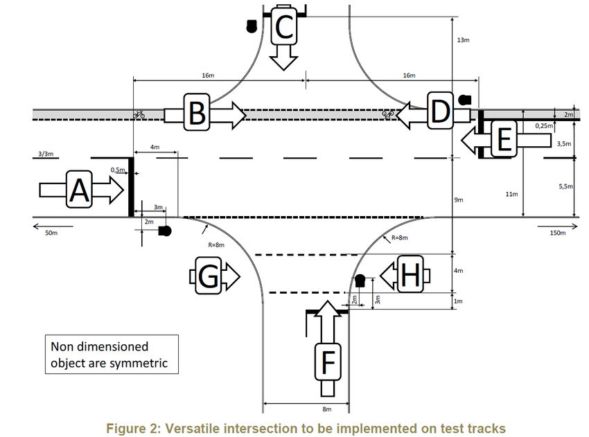
Further Extension of the “Classical”
Certification Approach
Why the testing of the automated driving systems requires new elements:
• The system complexity and thereby the number of software-based functions will continue to
  increase with automated driving systems. Compared to the complex electronic control systems,
  the potentially affected safety-areas and variances of scenarios will further increase and cannot
  fully be assessed with a limited number of tests that are performed on a test track or test bench.
• The existing audit-approach used for electronic control systems both in safety systems (e.g. ABS,
  ESP) and driver assistance systems (L1, L2) should be further extended and upgraded to tackle L3-
  L5 systems.
Why elements of the “classical” approach are still necessary:
• Testing of existing conventional safety-regulations should continue with the “classical approach”
  also for vehicles that are equipped with automated driving systems.
• Furthermore, classical certification elements (track testing) are an essential part of the three-
  pillar approach (see from slide 14). Additions are needed to appropriately cover the software
  related aspects – they will augment and not replace the classical certification approach.
Paradigm shift - new approach required
 Manual and assisted Driving Conditional Driving Automation High/Full Driving Automation
      „Classical“ approach                  „Classical“ approach                             „Classical“ approach
   (for a single system/component)        (for a single system/component)               (for a single system/component)

     Driving capabilities                 Driving capabilities                        Driving capabilities + more...
                                                Driving capability (DDT, OEDR) with
                                                the system during operation, but              Confirmed through
                                                handover to driver necessary

                                                                                         •    Audit/Assessment
                 Driving Permit                          Driving Permit                  •    Physical Certification Tests
                                                                                         •    Real-World-Test Drive
                 • Theoretical Test                       • Theoretical Test
                 • Practical test                         • Practical test
                 • Excerpt of driver‘s                    • Excerpt of driver‘s               New approach for
                   capabilities                             capabilities                     future certification

 e.g. vehicle with ADAS support (L1/L2)   e.g. vehicle with ACSF B2 (L3)                 e.g. vehicle with L4 system
                                                                                         without conventional driver
Overview: Concept for ADS Certification
Concept for certification – the three pillars
Overall impression of system behavior on public roads
Real- Assessment of system‘s ability to cope with real world traffic situations with a
standardized checklist
World- „Driving license test“ for automated driving system
Test Drive Guidance through given set of situations which shall be passed
Matching of audit/assessment results with real world behavior
Physical Assessment of system behavior in fixed set of challenging cases, which either
aren‘t testable on public roads or cannot be guaranteed to occur during the real
Certification world test drive.
Tests Reproducibility of situations is given
Audit of development process (methods, standards)
Assessment of safety concept (functional safety, safety of use) and measures taken
Audit and
Check of integration of general safety requirements and traffic rules
Simulation
Assessment Use of simulation results (high mileage approval, capability to cope with critical
situations, which aren‘t testable on proving grounds or in public)
Assessment of development data/field testing, OEM-self-declarations
Certification depends on all three pillars – partial assessment doesn‘t have significance
Scope of work should reduce with every step (audit/assessment: largest scope – real world test drive: final confirmation)
Safety for test witnesses and other road users – no endangering tests on public roadsExample of the different pillars’ functions
Typical traffic
Scenario probability of occurrence in real world traffic
Real World Test Drive
scenarios
Pedestrian crossing a crosswalk
Critical traffic Physical Certification
scenarios Tests
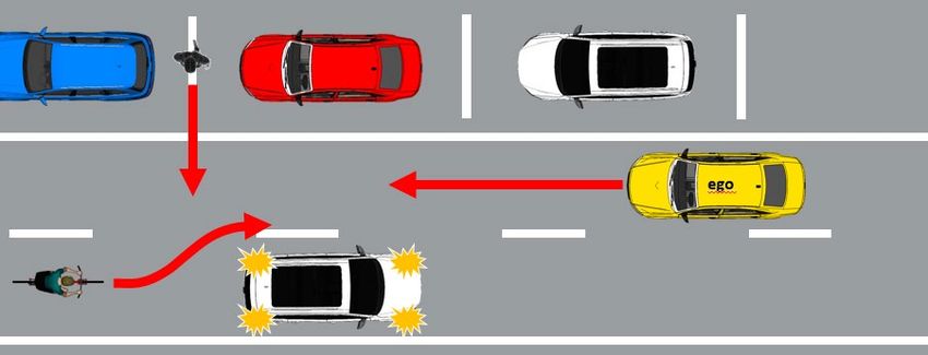
Obstructed pedestrian crossing
Edge case Audit and Assessment
scenarios (e.g. simulation)
low probability, but high
efforts to identify and
confirm performance!
Obstructed pedestrian crossing
Complexity/risk of scenario
+ cyclist overtakingConcept for certification – the three pillars
and their individual purpose
Audit/Assessment Physical Certification Tests Real World Test Drive
Simulation
- Understand the system to be certified - Assess critical scenarios - Assess the overall system
- Assess that the applied processes and that are technically capabilities and behavior
design/test methods for the overall difficult for the system in non-simulated traffic on
system development (HW and SW) are to cope with, have a public roads and show
effective, complete and consistent high injury severity (in that the system has not
- Assess system’s strategies/rest case the system would been optimized on specific
performance to address (multiple) fault- not cope with such a test scenarios
conditions and disturbances due to scenario) and are - Assess system safety
deteriorating external influences; vehicle representative for real requirements like e.g. HMI
behavior in variations of critical scenarios traffic and ODD
- Simulation: Test parameter variations (e.g. - Compare with critical - Assess that the system
distances, speeds) of scenarios and edge- test cases derived from achieves a performance
cases that are difficult to test entirely on a simulation and validate comparable to an
test track simulation tools experienced driverConcept for certification of automated driving systems Level 3-5 Why the new approach can generate an equivalent/higher safety-level compared to the “classical” approach: • The new approach recognizes established process and functional safety oriented audits for certification of complex electronic vehicle control systems as a foundation. • Consequently, the new approach requires manufacturers to give evidence that their system has been designed and tested in a way that complies with established safety principles, different traffic rules, and ensures safe performance both under fault-conditions and arbitrary external influences. • Furthermore, the new approach evaluates specific complex situations on a test track. • To complement the assessment, the new approach includes a real-world-drive test in real world traffic (non-simulated).
Mapping of Safety Principles and the Pillars
Comparison of published Safety Principles
Safety Principles USA (NHTSA FAVP 3.0) Japan (MLIT-Guideline) Canada (Transport Canada) Europe (EC Guidance)
Vision: “0” accidents with injury or fatality by ADV
Ensure Safety : Within ODD ADV shall not cause
Conclusions:
rationally foreseeable & preventable accidents
1 Safe Function
General safety-
1) System Safety ii) System safety by redundancy 6) Safety systems (and appropriate redundancies) 7) Safety assessment – redundancy; safety concept
(Redundancy) 9) Post Crash Behavior
2 Safety Layer 3) (OEDR) ii) Automatic stop in situations outside ODD
iii) Compliance with safety regulation
4) International standards and best practices 2) Driver/operator/ passenger interaction
- takeover delay; camera & voice link for driverless
frameworks
iii) Compliance with standards recommended
vii) for unmanned services: camera link &
systems
are available.
They are not
notification to service center
3 Operational Design 2) Operational Design Domain i) Setting of ODD 2) Operational design domain 1) System performance in automated mode – description
Domain 2) Driver/operator/ passenger interaction – boundary
detection
design-
4 Behavior in Traffic 3) OEDR 3) OEDR 1) System performance in automated mode – behavior restrictive and
12) Federal, State and local Laws 4) MRM – traffic rules; information
5 Driver‘s iv) HMI – driver monitoring for conditional 1) Level of automation and intended use 2) Driver/operator/ passenger interaction – information;
could be
Responsibilities automation 7) HMI and access of controls – accidental misuse driver monitoring
further
6 Vehicle Initiated 4) Fallback (MRC) ii) Automatic stop in situations outside ODD 3) Transition of driving task – lead time; MRM; HMI explored for
Take-Over 6) HMI iv) HMI – inform about planned automatic stop 4) MRM
7 Driver Initiated 6) HMI 7) HMI and Accessibility of Controls 1) System performance in automated mode - takeover
regulatory use
Transfer
8 Effects of Automation
at UNECE
7) HMI and Accessibility of Controls – unsafe misuse
9 Safety Certificate viii) Safety evaluation via simulation, track & real 5) Testing and validation 7) Safety assessment – product; processes; risk
world testing
ix) In-use safety - inspection
11) After market repairs / modifications assessment; standards
Internationally
10Data Recording 10) Data Recording v) Installation of data recording devices 12) User privacy
13) Collaboration with government agencies & law
5) Data storage system harmonized
enforcement
safety
11Security
principles
7) Vehicle Cybersecurity vi) Cybersecurity – safety by design 10) Cyber security 6) Cyber security
ix) In-use safety – software update 11) System update
12Passive Safety 8) Crashworthiness 9) User protection during collision & system failure
endeavored by
13Driver‘s training
OICA
11) Consumer Education/Training x) Information provision to users 8) Public education and awareness 8) information provision to usersCoverage of safety principles by the pillars
X = OICA views on how some requirements Audit/ Real-World-Test-
could be reasonably addressed Track Testing
Assessment Drive
Safety Principles
1 Safe Function (e.g. failure strategy, redundancy concepts, etc.) X
2 Safety Layer (OEDR, Emergency Maneuvers)
X X X
3 Operational Design Domain (definition, recognition of the limits) X X
4 Behavior in Traffic (OEDR, compliance with traffic laws) X X
5 Driver‘s Responsibilities (HMI, Driver Monitoring) X X X
6 Vehicle Initiated Take-Over (Minimum Risk Maneuver, transition
scenario, HMI, etc.) X X X
7 Driver Initiated Transfer (e.g. activation, deactivation, override) X X X
8 Effects of Automation (Driver Monitoring, System Design, driver’
support) X
9 Safety Certificate (in-use-safety, testing and validation, etc.)
X X X
10 Data Recording X may be by conventional regulation
11 Security
X may be by conventional regulation
12 Passive Safety Testing of existing conventional safety-regulations continues with the “classical approach” (update of such regulations will be
necessary)
13 Driver‘s training XBack-Up
References
This presentation is based on several documents that OICA submitted under the activities of WP.29
IWG ITS/AD and under the former TF AutoVeh including its subgroups 1 and 2:

- ITS_AD-12-11            - TFAV-02-05              - TFAV-SG1-02-08          -SG1-03-10
- ITS_AD-13-05-Rev1       - TFAV-SG1-01-02          - TFAV-SG2-02-07
- ITS_AD-14-07            - TFAV-SG1-01-03
                          - TFAV-SG1-01-04
                          - TFAV-SG1-01-05
                          - TFAV-SG2-01-02
Overview: Concept for ADS Certification
Academia views on why a different approach
is needed
• Autonomous vehicles would have to be driven hundreds of millions of miles and sometimes
  hundreds of billions of miles to demonstrate their reliability in terms of fatalities and injuries —
  an impossible proposition if the aim is to demonstrate their performance prior to releasing them
  on the roads for consumer use and even then, this would not ensure that all safety-relevant
  situations occurred. (see e.g. also next slide based on German accident data base)
• Developers of this technology and third-party testers will need to develop innovative methods of
  demonstrating safety and reliability.
• In parallel to developing new testing methods, it is imperative to develop adaptive regulations
  that are designed from the outset to evolve with the technology so that society can better
  harness the benefits and manage the risks of these rapidly evolving and potentially
  transformative technologies.
Source: See e.g. research conducted by Prof. Dr. Hermann Winner (Technical University Darmstadt) and publication by RAND Corporation, 2016
Challenge of validation.
  Statistics Mileage and Accidents
                                                                        Accident Statistics Germany (Destatis 2016):
          material damage:                                              726 bn km         total mileage
                                                                        13,341 km         annual mileage per driver
          0.3 mn km
                                                                        2,277,182         material damages
          slightly personal damage:                                     329,240           slightly injured
                                                                        67,426            severely injured
          2.2 mn km                                                     3,206             fatalities
              severe personal damage:                                                         fatal accident:
              11 mn km                                                                        226 mn km

      0                  50 mn          100 mn            150 mn             200 mn                    250 mn

average annual mileage : 0.013 mn km;
average mileage lifetime: 0.7 mn km
(~50 years x 13tsd km)                     near accidents (schematic)
Definitions: „use-case“ vs. „test scenario“
“Use cases” for automated driving in the sense of the proposed certification concept are areas of
application in relevant traffic environments:
• “Highway/motorway traffic” means a traffic environment in which traffic flows on multilane
highways often with high maximum allowed speeds. Characteristic is that the lanes with traffic
flow in opposite direction are separated from each other. Also there are typically no
intersections and no traffic lights (except some tunnels or bridges).
• “Urban traffic” means an environment (typically in a city) where maximum speed is limited to
[e.g. 50-60 kph].
• “Interurban traffic” means a traffic environment in which traffic flows does not necessarily flow
on multilane highways, however high maximum speeds are allowed. Besides, lanes with traffic
flow in opposite direction are not fully separated from each other. Also there may be
intersections and traffic lights.
“Test scenarios” for automated driving in the sense of the proposed certification concept are
challenging maneuvers that are physically tested on test tracks (e.g. an obstructed pedestrian
crossing the street or an emergency braking maneuver before the tail end of a traffic jam)Overall driving capabilities for the use-case
„motorway/highway traffic“
• Depending on the foreseen use-case, an autonomous driving system shall be capable of handling
the following typical traffic scenarios representative of motorway/highway driving or in case of an
automated driving system may request the driver to take-over with sufficient lead time
(requirements concerning transition scenario apply)
• Normal traffic flow: lane keeping, distance keeping, road speed compliance, lane changes
(including motorbikes on adjacent lanes in the rear), merging, road signs
• Entering and exiting highway: exit, gas station, recreational parking site
• Passing slower vehicles
• Ending lanes
• Construction sites
• Scenarios involving emergency vehicles (police, ambulance, fire brigade)
• Objects/obstacles on the road (e.g. lost cargo)
• Policeman or roadman directing traffic
If the manufacturer can provide evidence that certain requirements are not relevant due to the
foreseen use-case (e.g. no automatic lane change foreseen), the respective requirements are not
applicable.Overall driving capabilities for the use-case
„urban traffic“
• Depending on the foreseen use-case, an autonomous driving system shall be capable of handling
the following typical traffic scenarios representative of urban traffic:
• Normal traffic flow: lane keeping, distance keeping, road speed compliance, lane changes
(including 2-wheelers on adjacent lanes in the rear), merging, signs
• Intersection scenarios: traffic lights, signs, right of way rules, protected and unprotected
turning
• Roundabout scenario
• Scenarios involving pedestrians and cyclists: walkway, turning left/right
• Scenarios involving emergency vehicles (police, ambulance, fire brigade)
• Objects/obstacles on the road (e.g. lost cargo)
• Policeman or roadman directing traffic
• Bus stations (school bus)
• Tram way / Cable cars crossing vehicle road; parallel to vehicle road
If the manufacturer can provide evidence that certain requirements are not relevant due to the foreseen
use-case (e.g. the autonomous driving system can only be activated on a dedicated geo-fenced city-route
where traffic lights are not existent), the respective requirements are not applicable.Concept for certification – the three pillars – their
individual strengths (+) and weaknesses (-)
Use-Cases: Urban, Highway, Interurban, [Parking] for automation levels 3, 4 and 5
Requirements address vehicle behavior in road traffic and further general safety requirements
Audit/Assessment Physical Certification Tests Real World Test Drive
Simulation
OEM provides e.g.: Dedicated, reproducible challenging Test drive to assess the vehicle’s
Safety concept / functional safety tests under worst-case vehicle standard behavior in public road
strategy; simulation and development configurations for specific scenarios traffic, compliance with traffic laws
data to verify vehicle behavior in edge that cannot be guaranteed to occur and maneuvers according to defined
cases; manufacturer’s self declarations in real world test drives checklist
etc. + Objective performance criteria + Limited testing efforts/duration
+ Limited testing efforts for − Significant testing efforts + Many situations may occur
certification − Transfer of requirements into vehicle must be capable to
− Requires highly skilled and qualified reproducible tests technically handle
test house/certification agency to difficult or likely to result in − Requires highly skilled and
appropriately assess data/ remarkable functional qualified test house/certification
documents/ systems, possibly restrictions agency to appropriately assess
subjective judgements systems behavior, possibly
subjective judgements
A proper combination of all 3 pillars allows for compensation of the weaknesses of each single methodWhat’s behind the three pillars
Audit & Assessment
Overview of complete certification structure
                                                                             Certification
                                                                of Automated Driving Systems (L3-L5)
                                                           Objective: System is safe and technical compliant

                              Audit and Assessment                                     Physical Certification Tests                   Real-world-test-drive

    Audit: Development                   Highway/       Inter-urban/
                                                                            Urban
                                                                                     Highway/
                                                                                                    Urban
                                                                                                                Inter-urban/    Highway/
                                                                                                                                                Urban
                                                                                                                                                             Inter-urban/
processes and methods (use-              Motorway           rural                    Motorway                       rural       Motorway                         rural
     case independent)
                                           Assessment: Safety concept to                        Test scenarios                    Test drive under real conditions
Pass/fail criteria: tbd (e.g. criteria   address fault/non-fault conditions                   (use-case-specific)                        (use-case-specific)
 of existing technical standards
          like ISO 26262)                       General system safety
                                                                                            Pass/fail criteria: Defined             Pass/fail criteria: Individual
                                                   requirements
                                                                                       performance requirements and test               qualitative checklist
 Implementation and change
                                                                                          procedures under dry/normal
 management regarding traffic                         Traffic rules                                conditions
       laws and rules

Safety-relevant areas: Assess that         Safety-relevant areas: Assess system’s             Safety-relevant areas:
    the applied processes and             strategies/rest performance to address         Assess critical scenarios that are        Safety-relevant areas: Assess the
 design/test methods for overall               (multiple) fault-conditions and        technically difficult for the system to     overall system capabilities in typical
  system development (HW and                 disturbances due to deteriorating        cope with, have a high injury severity       traffic scenarios; general system
 SW) are effective, complete and          external influences; vehicle behavior in     (in case the system would not cope            safety requirements like HMI;
            consistent                          variations of critical scenarios      with such a scenario) and are likely to     behavior in some fault-conditions?
                                                                                                occur in real traffic
Audit structure: Processes and documentation
Certification
of Automated Driving Systems (L3-L5)
Objective: System is safe and technical compliant
Audit Focus: Processes and Documentation
System layout/architecture Description of the components and Identification of relevant
and schematics functions HW and SW
Purpose: Understand the
Documentation of the system system to be audited and List of all input and sensed variables Description of the ODD (boundaries of functional
assessed operation)
List of all output variable controlled by
the system Signal flow chart and priorities
Safety analysis Safety plans of the system and
of relevant components/ECUs
Purpose: Assess that the
Pass/fail criteria: tbd
applied processes and Development process incl. Development process plans (e.g. criteria of
Processes and methods (use-case design/test methods for Specifications management, Testing, and quality management existing technical
independent) overall system development Failure Tracking plans standards like ISO
(HW and SW) are effective, Requirements’ implementation
26262)
complete and consistent
Implementation and change
Validation and change/
management regarding traffic laws and
release management plans
rules
OEM to provide for inspection OEM to submit to technical serviceAssessment Structure: Safety Concept and Validation
Certification
of Automated Driving Systems (L3-L5)
Objective: System is safe and technical compliant
Assessment Focus Safety Concept and Validation
Safety Goals Purpose: Identify all safety relevant* hazards
Purpose: Assess the and risks
Hazard Analysis and Risks Assessment (HARA)
system’s
Pass/fail criteria:
strategies/rest Functional Safety Concept Purpose: confirmation of the process
-The system is fail-
performance to
Assessment Reports Purpose: Analyze failure modes, occurrence operational;
address (multiple)
Failure Mode and Effects Analysis (FMEA) probabilities, severity/effects and detection -The system can cope
fault-conditions and
Fault Tree Analysis (FTA) capabilities with all relevant
disturbances due to
Safety external/environmen
deteriorating Matrix of all failures, failure simulation and Purpose: Identify all non-fault conditions
concept to tal conditions;
external influences; strategy, safe state/minimal risk condition (e.g. disturbances/environmental
address -The system can cope
vehicle behavior in constraints) that lead to a safety-
fault- and with all relevant
variations of critical relevant*/traffic-compliance-relevant
non-fault Safety of the Intended Functionality (SOTIF) traffic scenarios;
scenarios system behavior
conditions -The system does not
System/component specifications Purpose: Consistent requirements endanger under fault-
*Safety-relevant: management and non-fault
Behavior that results Integration/Implementation testing: Testing Purpose: Verification that the safety conditions other
in unintended and Safety Assessment Reports requirements are effectively implemented traffic participants
leaving of the ego-
lane or in a collision Safety-Case Purpose: Gives evidence (collects work
products) in a consistent/structured way
Manufacturers’ statement/self-declaration that the system is acceptably safe
OEM to make open for inspection OEM to submit to technical serviceAssessment Structure: Safety Concept and Validation
Certification
of Automated Driving Systems (L3-L5)
Objective: System is safe and technical compliant
Assessment Focus Safety Concept and Validation
General system safety Internal vehicle HMI
Requirements tbd in the regulation
requirements Part of this to be
(Annex 3 General requirements)
(exemplarily) covered by
Driver Monitoring OEM to explain the strategy and
real-world test drive and
the requirements’ implementation
in the system OEM self declaration
Transition Scenario
Integration/Implementation testing: Test
The system complies with Reports
Traffic rules traffic rules/traffic laws (Note: Analysis of relevant traffic
Self declaration
rules/laws is part of the process audit)
OEM to make open for inspection OEM to submit to technical servicePhysical Certification Tests on Proving Grounds
Relevant test scenarios on
proving grounds for the urban
    use-case – OICA views
Introduction/basis for discussion • The next slides are based on the concept document “Structure of a future Regulation of autonomous vehicles” that OICA provided to the TF AutoVeh at the meeting in Den Haag Special requirements for the use-case urban traffic: See Annex 5, paragraph 2: “Physical tests required for type approval/certification” • The intention of this presentation is to start the discussion and explain a proposal on four critical test scenarios for the urban use-case that are suitable for testing on proving grounds. There may be additional scenarios to be added • These four critical test scenarios for the urban-use-case were presented at the 1st meeting of the subgroup physical testing and audit in Den Haag (TFAV-SG1-01-02) and were supported by the group as a starting point. OICA was asked to continue the work for specifying reproducible tests (i.e. define parameters like e.g. speed and distances, infrastructure, targets, pass/fail criteria, test equipment etc.). • This updated presentation is based on TFAV-SG1-01-02 and adds a first collection of parameters that need to be defined when developing the test procedures. There may be additional parameters to be specified. • It should be noted that defined tests on proving grounds (test tracks) are only one single element in the overall concept of the system certification/assessment. Additional scenarios are addressed by other means e.g. during the real-world-driving test and the audit/assessment.
Scenario Justification
• In a first step, the proposed test scenarios were identified and evaluated with an “engineering
  judgement approach” based on two criteria:
   - Criteria 1: Performance based technical difficulty/complexity for the system to detect/manage
     the particular situation
   - Criteria 2: Injury/crash severity
• Remark: It was qualitatively considered that the scenarios should have a significant relevance
  /occurrence probability in traffic
• Outlook: Additional statistics/external sources could be added in mid- and long-term to complete
  the justification on a scientific basis
Proposal Test Track Scenarios „Urban“
2.1 Unprotected „left turn“ (in case of right hand traffic) Excerpt Parameters Test Procedure
Situation: The vehicle approaches an intersection in autonomous mode with the INITIAL CONDITIONS:
intention to perform a left turn. Other Dynamic Objects are present. Infrastructure: Crossing (dimensions, lane
Expected Behavior: The vehicle should automatically activate the left direction markings, design and position of traffic
indicator when slowing down. Then, the vehicle yields considering the traffic rules lights) see e.g. EU-Project PROSPECT,
from the corresponding country and turns left. design and position of speed sign on ego
Initial Condition: The vehicle follows the ego-lane and is heading an intersection lane before the crossing, area before
that is controlled by a traffic light without green arrows as status, by a yield sign or crossing to allow smooth acceleration of Ego
without any traffic elements at all. to reach initial speed
Final Condition: The vehicle has applied the left turn indicators and turned left Environment: Ambient temperature, track
according to the traffic rules without endangering oncoming traffic. The vehicle temperature, wind speed, ambient
drives on at the new lane. illumination etc.
Ego-Vehicle: Initial speed/speed range to
approach the crossing
Justification:
TEST MANEUVER:
Criteria 1: Technical difficulty/complexity for the system to detect/manage the situation
Vehicles V1: Speed/speed range, differential
- Path of other vehicles is difficult to predict/sense; high differential speeds
position/trajectory to Ego
Criteria 2: Injury/crash severity Options: Number and dimension of gaps
- High severity due to side impact and high speeds of involved vehicles between vehicles V1, trajectory of V1 (drive
straight or left/right turn)EU Project PROSPECT* – Standard Intersection
Layout
• EU-Project PROSPECT issued a draft
proposal for standard intersection
layout : “Deliverable D7.4 proposes an
intersection geometry that allows the
conduction of all intersection test cases
with no need to manipulate the lane
markings in-between tests: only tracks
for Vehicle-Under-Test and VRU Dummy
need to be reprogrammed, object
positions need to be shifted and
implemented.”
• OICA proposes to consider this
intersection geometry proposal for test
scenario 2.1 and 2.3
• Open point: Different intersection
layouts needed for other countries like
USA/CAN, China, etc.?
* Source: Proactive Safety for Pedestrians and Cyclists, European Commission, Eigth
Framework Programme, Horizon 2020, GA No. 634149; Deliverable D7.4Proposal Test Track Scenarios „Urban“
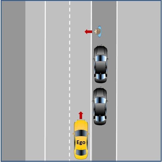
2.2 Obstructed Pedestrian crossing (without traffic lights, without pedestrian Excerpt Parameters Test Procedure
walkway) OICA proposal:
Situation: The vehicle follows in autonomous mode the ego-lane and approaches a Use established EuroNCAP maneuver CPNC-
gap after parked vehicles, where an obstructed pedestrian passes the street. 50 scenario (running child from nearside
Expected Behavior: The vehicle shall stop in a safe manner in order to avoid the from obstruction vehicles (see Test Protocol
collision. The vehicle can continue the drive, when the driving path is clear. AEB VRU systems, Version 2.0.2, November
2017)
Initial Condition: The vehicle follows the ego-lane and is heading towards an
obstructed pedestrian behind parked vehicles. A test protocol with all parameters is already
available. A carry-over to automated driving
Final Condition: The vehicle continues its drive without violating traffic rules as well
is possible with the only deviation that the
as safety and comfort criteria.
ego vehicle speed would not be constant
throughout the scenario and therefore the
pedestrian target’s trajectory needs to be
Justification: synchronized with the Ego vehicle speed
(the automated driving system can
Criteria 1: Technical difficulty/complexity for the system to detect/manage the situation
automatically reduce speed in the particular
- Dynamic obstacle test including obstruction of the pedestrian (child) dummy by other vehicles/objects driving situation).
on the side of the road is difficult to predict/sense; high differential speeds
Child pedestrian target: Specified by NCAP,
Criteria 2: Injury/crash severity speed 5 kph, synchronized trajectory
- High severity for an unprotected pedestrian if the vehicle does not safely stop depending on Ego vehicle trajectoryProposal Test Track Scenarios „Urban“
2.3 Cyclist test in combination with right turn Excerpt Parameters Test Procedure
Situation: The vehicle is driving with [50 km/h] in autonomous mode on a priority
INITIAL CONDITIONS:
road and approaches an intersection (vehicle has right of way or traffic light
“green”) to perform a right turn. A cyclist is driving with [15 km/h] in the same Infrastructure: Crossing (dimensions, lane
direction using a separate bicycle lane adjacent to the priority road and wants to markings for both vehicles and bicycles,
keep straight on across the intersection. A second bicycle is following with a [20m] design and position of traffic lights see
gap to the first, also driving with [15km/h]. e.g. PROSPECT intersection which includes
bicycle lane), design and position of speed
Expected Behavior: The vehicle should automatically activate the right direction
sign on ego lane before the crossing, area
indicator when slowing down, first stop and let the first bicycle pass and then use
before crossing to allow smooth
the gap between the first and the second cyclist in order to turn right.
acceleration to reach initial speed
Initial Condition: The vehicle follows the ego-lane.
Environment: Ambient temperature, track
Final Condition: The vehicle has applied the right turn indicators and used the gap temperature, wind speed, ambient
between the two cyclists for turning right. The vehicle drives on at the new lane. illumination etc.
Ego-Vehicle: Initial speed/speed range to
Justification:
approach the crossing
Criteria 1: Technical difficulty/complexity for the system to detect/manage the situation
TEST MANEUVER:
- Path of the cyclist that has a certain (parallel) distance to the road is difficult to predict/detect, relatively high
differential speeds Bicycles: Speed, synchronized trajectory
Criteria 2: Injury/crash severity depending on Ego vehicle trajectory,
- High severity for a protected/unprotected cyclist if the vehicle does not safely stop before making the right turn dimension of gap between bicycles, target’s
dimension (NCAP bicycle target available)Proposal Test Track Scenarios „Urban“
2.4 Obstacle test Excerpt Parameters Test Procedure
INITIAL CONDITIONS:
Situation: The vehicle follows in autonomous mode the ego-lane and reacts on static
objects located ahead of the vehicle on the driving lane while there is oncoming traffic Infrastructure: Lane dimensions and markings,
on the neighbor lane (so that there is not at all times a possibility for evading the static design and position of speed sign on ego lane
object). The static object may have different sizes, but is not moved by itself. before stationary object, area’s dimension
before object to allow smooth acceleration to
Expected Behavior: The vehicle has to decide if the static object is traversable or not. If reach initial speed
it is not traversable, the vehicle has to decide when it has to stop and when to
Environment: Ambient temperature, track
evade/drive around the static object.
temperature, wind speed, ambient illumination
Initial Condition: The vehicle follows the ego-lane. The vehicle is heading a static object etc.
in lane. Ego-vehicle: Initial speed/speed range to
Final Condition: The vehicle has just followed the ego-lane if the static object is approach the stationary object
traversable. If it is not traversable, the vehicle has safely (without endangering TEST MANEUVER:
oncoming traffic) driven around the obstacle to follow the ego-lane.
Vehicle V2: Speed; synchronized trajectory
depending on Ego vehicle trajectory
Justification:
Stationary object: Dimension (traversable/non-
Criteria 1: Technical difficulty/complexity for the system to detect/manage the situation traversable; extent of lane blockage), position
- Detect the stationary obstacle and then drive around/evade including consideration of oncoming traffic within the lane
is difficult! Note: The dynamic object that suddenly crosses the road would be covered by 2.2. and
requires different technical capabilities. Options: Number of approaching vehicles V2,
different differential speeds Ego to wait vs. Ego
Criteria 2: Injury/crash severity
to evade immediately), additional vehicles in
- High severity for drivers/passengers due to oncoming traffic
front of EgoNext steps - Agree on how to handle certain options/variants of the test scenarios in a next step to have transparency what elements the scenarios should include - Based on this, continue working on a draft specification of reproducible tests for the scenarios 2.1 – 2.4 (i.e. define numerical values/parameters like e.g. speed and distances, road infrastructure, definition of objects, pass/fail criteria, test equipment etc.). - OICA proposes to consider the intersection geometry proposal of the EU-Project PROSPECT for test scenario 2.1 and 2.3 and not to start a separate activity. Are different intersection layouts needed for other countries like e.g. USA/CAN, China, etc.? What is the expectation of the Contracting Parties? - Test Scenario 2.2 (Obstructed Pedestrian crossing): OICA proposes to use the existing EuroNCAP maneuver CPNC-50 scenario (running child from nearside from obstruction vehicles, see Test Protocol AEB VRU systems, Version 2.0.2, November 2017) with the only deviation that the ego vehicle speed would not be constant throughout the scenario (initial speed would be fixed, but the automated driving system may then automatically adapt its speed to the particular driving situation)
Testing of autonomous/automated
driving systems on proving grounds

   – The issue of “testability” –
            OICA views
Testability on proving grounds - Introduction
Background:
- Especially L3-L5 features are linked to a dedicated ODD*
and can only be activated and operated within this ODD*.
- This issue is a general and use-case independent, issue
that even affects ACSF (e.g. CAT C, B2), but has not been
resolved, yet. Proving grounds:
- Are typically not part of the geographic ODD*
- Do typically not reflect other technical ODD* requirements
- Are typically not included in high definition maps
Consequence: If dedicated ODD* conditions/premises are not
fulfilled, the automated driving system cannot be activated on
proving grounds and therefore not be tested
Example illustration
*Operational Design DomainTestability on proving grounds - Options
Option 1 2 3 4 5
Description Enable/adapt both proving Test maneuvers with ADS Limit physical testing of ADS Enable ADS equipped vehicles Enable/adapt specific test
ground infrastructure and high equipped vehicles on public equipped vehicles to OEM- with a so called „test mode“ vehicles by applying SW-
definition maps to allow for streets within the operational specific proving grounds (that allows remote operation) modifications (e.g. activate
physical testing of ADS design domain for physical testing on any SCN-coding) for physical testing
equipped vehicles proving ground on any proving ground
Advantages + Authorities/agencies can + Authorities/agencies can + Reduced implementation + Authorities/agencies can + Reduced implementation
independently from OEMs independently from OEMs efforts for OEMs independently from OEMs efforts for OEMs
conduct compliance tests with conduct compliance tests with + Testability of series systems conduct compliance tests with + Flexibility
any desired ADS equipped any desired ADS equipped vehicle no modification to any desired ADS equipped
vehicle on specific proving + Testability of series systems systems/software necessary vehicle on proving grounds
grounds no modification to + No difficulties with OEM-
+ Testability of series systems systems/software necessary specific attributes in high
no modification to definition maps as considered
systems/software necessary by OEM-proving grounds
Disadvantages/ - High implementation efforts - Road blocking may be possible - Independent execution of -Risk of unauthorized - No representative series
Challenges for OEMs in individual cases, but not certification tests not possible access/manipulation and systems/software
- Handling of OEM-specific realistic/practical as general for authorities/agencies – security threat due to external - Independent execution of
attributes (IP-issue?) in high solution worldwide causes problems for rating/ interface certification tests not possible
definition maps that need to - Safety reasons in case of on compliance-Testing, CoP und - No representative series for authorities/agencies –
be reflected by proving road-tests and many other things market surveillance systems/software causes problems for rating/
grounds likely not easy/practical to test on - Not realistic/practical as compliance-Testing, CoP und
- Handling of new proving public roads solution worldwide market surveillance
grounds that were not
existent at the time of
production (map update of
proving ground)
- Maintenance issues
OICA’s conclusion: Simultaneous investigation of option 3 (short-term solution) and option 1 (long-term solution ) seems to be useful and reasonable approachNext steps - What is the expectation of the Contracting Parties regarding testability on proving grounds? - Can it be assumed that certification agencies/authorities etc. want to be able to independently test and assess vehicles/automated driving systems on certain proving grounds (e.g. relevant for certification-tests, in-use-compliance-tests, conformity of production, rating tests NCAP, etc.)? - If yes, option 1 requires that proving ground infrastructure and attributes in proving ground maps fulfill certain harmonized criteria to enable testability of different kinds of systems of different manufacturers - The discussion on standardization of such criteria/map attributes needs to start as soon as possible and is expected to take a longer time as several technical issues need to be properly resolved (e.g. handling of OEM specific attributes, handling and transferring of map data to the different kinds of systems, etc.) - Would a combination of option 1 and 3 be an acceptable approach? E.g. Option 3 as a short- and midterm solution and option 1 as a long-term solution? both options should be investigated and developed simultaneously
Real-World-Test-Drive
Real World Test Drive – OICA views
Introduction/basis for discussion
• The next slides are based on the document “Real world test drive” (TFAV-
  SG2-01-02) that OICA provided to the TF AutoVeh meeting in Den Haag.
• The intention of this presentation is to start the discussion and explain a
  proposal on how a real world test drive can fit into the overall concept for
  the certification of AVs developed by OICA.
• Several conceptual issues that were raised during the meeting. OICA was
  asked to further develop / clarify these items.
• This updated presentation includes these further explanations to the
  original document. New sections appear in blue font.
Road Test for AVs: Understanding its Role in
the Certification Process

• What is the road test supposed to demonstrate? What is its role in
  the entire certification process?
• What is the suggested content?
• Which assessment approach is considered?
• How could the road test look like from a procedural and timing
  perspective?
WHAT IS THE ROAD TEST SUPPOSED TO DEMONSTRATE? WHAT
IS ITS ROLE IN THE ENTIRE CERTIFICATION PROCESS (1/2)?

Hypothesis:
The road test is going to demonstrate the capability of the vehicle
to adhere to traffic rules [and maneuvers according to the general
expectations of other road users].

This capability is brought to the driving task currently by the
experienced / approved driver.

 14.01.2019                                                           52
WHAT IS THE ROAD TEST SUPPOSED TO DEMONSTRATE? WHAT
IS ITS ROLE IN THE ENTIRE CERTIFICATION PROCESS (2/2)?

The road test is an integral building block in the assessment and
certification of automated vehicles. That said it is not suggested that this
is the one and only deciding criteria for certification.

The road test is going to address typical / normal traffic scenarios that a
human driver is exposed to on a regular basis.

After this road test the generic „competence“ of the vehicle is
documented to adhere to traffic rules and the assessor has the ability to
declare if it moves in traffic without becoming an obstacle.

 14.01.2019                                                              53
COVERAGE OF SCENARIOS
 - to be addressed according to the use case -

                                                                     „Typical“ Driving –
                                                                     Real World Test Drive

                                                                     Demanding Traffic
                                                                     Scenarios –
                                                                     Physical Tests

                                                                     Edge Cases –
                                                                     Simulation

With the approach suggested by OICA all traffic scenarios can be addressed appropriately
                                                                                         54
DEFINITION OF “REALISTIC / TYPICAL / NORMAL” TRAFFIC CONDITIONS • > 90 % of all road trips are „un-eventful“ because the driver does not have to deal with challenging scenarios or edge cases • During these trips the adherence to traffic rules, showcasing a behavior that is understood by other road users and participating in the traffic without being an obstacle to other road users is the prime role of the driver, i.e. the automated system in the future. Therefore, traffic scenarios as suggested in the „checklists“ – see below – fullfil this criteria
WHAT IS THE SUGGESTED CONTENT?

Hypothesis:
Automated/ autonomous vehicle will not operate at the beginning
under all conditions and on all roads. The initial focus will be on the
use cases called „highway“ and „urban“ driving.

Consequently, the content of the road test will have to be adjusted
to these use casses (i.e. test scenarios of traffic situations).

Note: the minutes of the SG2 session state that the group should „start with urban situations, while
ACSF continues with highway situations.“

  14.01.2019                                                                                           56
WHAT IS THE SUGGESTED CONTENT?
The selected scenarios will have to be derived after assessment from
various sources. Ultimate goals is to generate a data base filled with traffic
scenarios with which the statistical relevance of scenarios can be assessed
and changes to traffic cenarios can be document.

A vehicle can – based on the input of the vehicle manufacturer – be
nominated for one or more use case related road tests.

Limitations of the automated / automonous system will be reflected,
assessed and documented based on the input provided by the vehicle
manufacturer. This includes weather conditions, speed restrictions, non
supported roads (e.g. tunnels). For identified limitations, the HMI approach
needs to be assessed during the real world test drive to ensure that an
appropriate hand-over is initiated by the system and that the system can
recognise the limitations.

 14.01.2019                                                                    57
WHICH ASSESSMENT APPROACH IS CONSIDERED?

Hypothesis:
Based on a checklist the assessor exposes the vehicle to a pre-defined
number of mandatory scenarios to maintain objectivity and
comparability between road tests. Additional scenarios (supplementary
ones) can be tested as well according to availability.

Comments should be provided on the checklist after a scenario has
been completed indicating whether it was successful or not. Additional
comments – if necessary – can be provided as well.

 14.01.2019                                                          58
OICA proposal for checklists as Brief description of test route/location
integral part of the road test
Date/time of test drive
Item # Situation Pass Comments (must be filled out in case of
Yes No/ “no/unclear”)
unclear
Part A: mandatory All lines in Part A have to be evaluated during the test drive
• Suggests splitting into a mandatory and a HA.1
HA.2
Entering the highway
Following other vehicle in same lane
supplementary section HA.3 Passing a slower vehicle: lane
change/Passing/merging back in
previous lane
• All mandatory aspects need to be covered while HA.4
HA.5
Adapting to changing speed limits
Merging from an ending lane
supplementary aspects can help to refine the HA.6
HA.7
HA.8
Exiting the highway
understanding of the vehicle performance in real
HA.9
HA.10
traffic Part B: supplementary If any of the following situations is encountered during the test drive
this shall be noted in the respective line.
Additional considerations:
Additional lines may be added for situations not listed which were
observed.
HB.1 Situation involving an emergency
vehicle (police, ambulance, fire
• Across the markets (e.g. the EU) similar but not HB.2
brigade)
Policeman or roadman directing
traffic
same traffic rules and expected behaviors apply
HB.3 Objects/obstacles on the road (e.g.
lost cargo)
HB.4 Driving through construction site (if
(example: how to approach a pedestrian
possible with modified lane
markings)
HB.5 Driving through area with no/bad
lane markings
crossing and when to stop) HB.6
HB.7
HB.8
Safely approaching end of traffic jam
Driving in traffic jam
Driving through area with bad road
OICA suggests to not make this part of the HB.9
HB.10
surface conditions
road test but consider this for the „Audit“ pillarEXAMPLES FOR A CHECKLIST – HIGHWAY DRIVING (1/2)
Brief description of test route/location
Date/time of test drive
Item # Situation Pass Comments (must be filled out in case of “no/unclear”)
Yes No/
unclear
Part A: mandatory All lines in Part A have to be evaluated during the test drive
HA.1 Entering the highway
HA.2 Following other vehicle in same lane
HA.3 Passing a slower vehicle: lane
change/Passing/merging back in previous
lane
HA.4 Adapting to changing speed limits
HA.5 Merging from an ending lane
HA.6 Exiting the highway
HA.7
HA.8
HA.9
HA.10
14.01.2019 60You can also read


