PVI-AEC-EVO Monitoring System - QUICK INSTALLATION GUIDE - germansolar
←
→
Page content transcription
If your browser does not render page correctly, please read the page content below
PVI-AEC-EVO
                      Monitoring System

              QUICK INSTALLATION GUIDE

Note: This document contains proprietary information of Power-One, Inc.
The contents of this document or any part thereof should not be reproduced or disclosed
to any third party whitout Power-One’s express written consent.

Note: Any changes / modification not approved by the responsible party could void the
      user authority to operate the equipment.
CONTENTS

A.

B.

C.

D.

E.

F.

G.

H.

I.

L.

M.

           1 - EN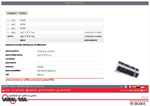
EN - ENGLISH
                                             Monitoring System

A.       Product Description
The PVI-AEC-EVO is a monitoring and checking system for photovoltaic systems made with Power-One Aurora
products.
The product allows to acquire parameters from the inverter and string-comb (in accordance with the design of the
central inverter monitoring system) through the RS485 line with the Power-One proprietary protocol.
The system is equipped with two equivalent RS485 ports and each of them allows a maximum of 62 string inverters
or 62 55kW conversion modules to be acquired.
The system is equipped with three analog inputs for the connection of sensors for the measurement of
environmental parameters:
The system also has six digital inputs for acquiring state signals (for example auxiliary contacts of power switches)
which are associated with state alarm conditions.
With respect to the user interface, the system is equipped with a 2x16 character display and four keys as well as an
integrated webserver with htm pages which are accessible through LAN connection.
The initial system configuration (check that the inverter parameters are acquired, analog inputs configuration, LAN
network parameters configuration) can be carried out completely through the display and keys; for displaying the
detailed parameters of the inverters and/or of the string-combs, as well as for the advanced configurations it is
necessary to access the pages of the integrated web server.
The PVI-AEC-EVO works together with a free web portal service: The system periodically transmits the data to the
portal management server and graphically shows the data on web pages which are accessible through an account
that can be requested from Power-One customer service.
The portal can also be used for sending alarm, report and FW update notification emails: The system FW can be
updated directly through the portal without the need for technical intervention on site.
The FW can also be updated locally without connecting to the portal.

                                                       2 - EN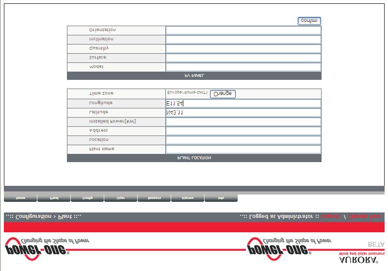
B.       User interface and use of the display
The system features a 2x16 character display,four buttons for navigating menus,and three LEDs to indicate device status.
Using the display and the buttons on the front panel it is possible to perform the initial configuration of the system (check
of parameter acquisition from inverter,analog input configuration,and configuration of LAN network parameters).
For displaying the detailed parameters of the inverters and/or of the string-combs, as well as for the advanced
configurations it is necessary to access the internal web server following the procedure described in paragraph H.
A list of functions accessible from the display is shown in the table in Appendix 3.

     Power ON              Power supply available                        Power supply not available              /
      Bus ON       Power supply of the expansion BUS available Power supply of the expansion BUS not available   /
       Fault                            /                                              /                         /

                 'Enter' button. Used to confirm an action,to access the main menu or the sub-menu corresponding to
                 the selected entry (indicated by the > symbol),or to go to the next digit to change.

                 'Down' button. Used to scroll down through the menu items, or to scroll the numerical scale in
                 descending order.
                 'Up' button. Used to scroll up through the menu items, or to scroll the numerical scale in ascending
                 order.
                 'Esc' button. Used to return to the previous menu or to return to the previous digit to change.

  To perform the initial configuration it is necessary to access the various display menus as administrator.
  Press the 'ENTER' key (    ) and insert password        : To insert the password press the arrow keys (           ) to
  change the value and the 'ENTER' key to confirm the value. This password gives access to all the display setting sub-
  menus.

                                                                3 - EN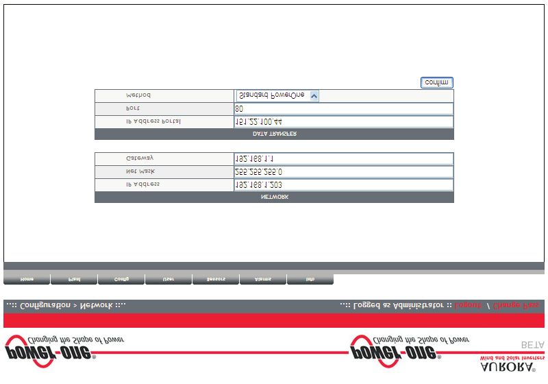
EN - ENGLISH
                                                         Monitoring System

C.      Pin-Out of System Connectors
The diagram below shows the pin-out of the connectors which allow the system connection.

        J5
        RELAY
        1) RELAY 1                                                                 J17              J15
        2) RELAY 1_RTN                                                             RS485/1          RS485/2
        3) RELAY 2                                               S2                1) RTN           1) RTN                S1
        4) RELAY 2_RTN
        5) RELAY 3
                                  J12                    120Ω TERM.                2) - T/R         2) - T/R            120Ω TERM.
                                  GROUND                   RS485/1                 3) +T/R          3) +T/R               RS485/2
        6) RELAY 3_RTN                                                             4) +5V           4) +5V

                                             1       2       3   4    5   6                    4 3 2 1   4 3 2 1

                                                                                                                                   J9
                                                                                                                                 EXPANSION
                                                                                                                                    BUS

                              1   2              2       1           1 2 3 4 5 6          1 2 3 4 5 6    1 2 3 4 5 6

  J7              J18                 J8                              J3                      J20                  J4
  LAN             BATTERY IN          Vin DC                          ANALOG INPUT            DIGITAL I/O          DIGITAL I/O
  IEEE802.3u      1) + Batt.          1) + Vcc                        PT100/1000              1) RTN 1             1) DIn 2
                  2) - Batt.          2) - Vcc                        1) PT_ALIM              2) RTN 1             2) DIn 3
                                                                      2) PT_SENSE             3) DO_PWM 2          3) DIn 4
                       NOTE:             INPUT DC:
                 Only for dedicated   24 V DC 0,3 A                   3) PT_RTN               4) DO_PWM 1          4) DIn_RTN
                     accessory             NOTE:
                                                                      4) AIn_RTN              5) DIn 1             5) DIn 5
                 PVI-BATTERY-PACK     Use the provided                5) AIn 1                6) DIn_RTN           6) DIn 6
                                       power supply                   6) AIn 2

                                                                          4 - EN
D.       Power Supply Connections and System Start Up
1. Connect the power supply to the power supply network (110/230V 50/60Hz): the "Power" led on the power
   supply will light up steadily.Check that the output voltage of the power supply is 24Vdc.Disconnect the power
   supply from the power supply network.
2. Connect the output of the power supply to the power supply terminal block of the PVI-AEC-EVO respecting the
   polarity and using the wiring provided.
3. Connect the power supply to the power supply network: After a first starting phase (lasting about 30 seconds)
   during which the system is not able to receive any input from the user, the green "PowerOn" led will remain lit.
   The message“PVI-AEC-EVO...." (in the first of the two lines) and date/time (in the second of the two lines) will
   be displayed.

                                        +   +   -    -

                                        Output DC
                                        24V 0.75A

                                                DC
                                                OK
                   STEP POWER

                      Input AC
                      100-240V                                     2   1

                          L(+)   N(-)

            L(+)                            N(-)         -Vcc              +Vcc

                                                                                   50-60 Hz
                                                                                  100-240 V~

                                                          5 - EN
EN - ENGLISH
Monitoring System
E. Date and time settings
1. Enter the main menu as administrator (See par.'B').
2. Access the menu 'SETTINGS' > 'DATALOGGER' and then select the 'SET DATE' sub-menu. This enables to set the
correct date in the system.
3. Return to the menu 'DATALOGGER' and then select the 'SET TIME' sub-menu. This enables to set the correct time
in the system.
SET PIN TO 0010
PVI-AEC-EVO ...... menu pin
12.00.00 01/01/11 ENTER 0*** CHANGE VALUE
NEXT ENTER
DIGIT
>settings >datalogger
change password ENTER io settings ENTER
>set date >set date
set time ENTER 01/01/11 CHANGE VALUE
NEXT ENTER
FIELD
>set time >set time
network ENTER 12.00.00 CHANGE VALUE
NEXT ENTER
FIELD
F. Connection of the RS485 line and inverter acquisition
check
The connection of the RS485 line must be carried out respecting the pin-outs of the J15 and/or J17 connectors. It is
recommended to connect the RS485 line when all the equipment is switched off (both the monitoring system and
the inverters) and to start up the monitoring system first and then the inverters. It is recommended to:
l Use a cable for RS485 applications with the following characteristics: 1 twisted pair + 1 conductor or two
twisted pairs, Screen and characteristic Impedance equal to 120Ω. For further information on the cable to be
used refer to Appendix 2.
l Make sure the signals correspond.
l Make sure that all three lines (+T/R,-T/R and RTN) are connected according to the diagrams on pages 8 - 9.
l Make sure that the communication line screen is grounded in one single point (according to the diagrams on
pages 8 - 9).
l Make sure that each element in the chain (each inverter or each 55kW module) has a RS485 address that is
different from the others.This address can be set via the display of the inverter.
6 - ENWhen connecting multiple units (string inverter or/and 55kW conversion modules) it is necessary
to wire the RS485 communication line according to the daisy-chain diagram (enter-exit).
The last inverter of the daisy-chain must be 'terminated' by activating the termination resistance of
the 120Ω communication line through switching the dip-switch located on the motherboard in the
string inverters,and inside each framework of the central inverters.
The maximum number of units (string inverters or/and 55kW conversion modules) that can be
connected to a RS485 port of the PVI-AEC-EVO is 62. In order to connect a number of units greater
than 62 it is necessary to use the second RS485/2 port respecting the same wiring diagram used for
the main RS485/1 port.
In case of mixed systems, the presence of both string inverters and central inverters on the same
RS485 line is permitted.To wire this line follow all the directions above.
All inverters (except for models PVI-5000/6000) have a clamp that allows giving continuity to the
cable screen of the RS485 line.
For single-phase inverters this clamp is indicated by the words LNK, for three-phase inverters it is
indicated by SCLD and for central inverters by X23.
For further details on the wiring of the RS485 line and/or the activation of the termination
resistances,refer to the user manual of string inverters and to the user manual of central inverters.
7 - ENMake sure that each
inverter in the chain has a
RS485 address that is
different from the others.
AURORA
AURORA
AURORA
OFF OFF OFF
ON ON ON
-T/R
-T/R
-T/R
RTN
RTN
RTN
+T/R
+T/R
+T/R
120Ω 120Ω 120Ω
Term. Term. Term.
RS485 Resistor RS485 Resistor RS485 Resistor
120Ω TERM.
RESISTOR ON
8 - EN
RTN
Monitoring System
+T/R
-T/R
OFF OFF
4 3 2 1 4 3 2 1
ON ON
RTN
RTN
-T/R
-T/R
+T/R
+T/R
120Ω TERM. 120Ω TERM.
RS485 RESISTOR RS485 RESISTOR
RTN +T/R -T/R RTN +T/R -T/R
120Ω TERM. 120Ω TERM.
RESISTOR ON RESISTOR OFF
EN - ENGLISH120Ω TERM. 120Ω TERM. 120Ω TERM.
RESISTOR ON RESISTOR OFF RESISTOR OFF Make sure that each
55 kW module in the chain
has a RS485 address that is
different from the others.
X20 X21 X22 X23 X24 X25 X26 X27 X20 X21 X22 X23 X24 X25 X26 X27 X20 X21 X22 X23 X24 X25 X26 X27
D D D
A A A
120Ω TERM.
RESISTOR ON
9 - EN
RTN
+T/R
-T/R
RTN +T/R -T/R RTN +T/R -T/R
4 3 2 1 4 3 2 1
D D
A A
X20 X21 X22 X23 X24 X25 X26 X27 X20 X21 X22 X23 X24 X25 X26 X27EN - ENGLISH
Monitoring System
After carrying out these checks, start up first the monitoring system and then the inverters. The system automatically
carries out a scan of the RS485 bus and automatically detects the available inverters.The presence of the inverters can be
checked directly from the display.
1. Enter the main menu as administrator (See par.'B').
2. Access the 'CURRENTVALUES' > 'ENERGY INVERTERS' menu (to display the string inverters) and/or 'CURRENTVALUES'
> 'ENERGY RACK' (to display the 55kW conversion modules). The number of inverters detected during the scan will
be displayed; the list of the monitored inverters identified by the Serial Number (S/N) can be displayed by scrolling
using the arrow keys ( ).
SET PIN TO 0010
PVI-AEC-EVO ...... menu pin
12.00.00 01/01/11 ENTER 0*** CHANGE VALUE
NEXT ENTER
DIGIT
>CURRENT VALUE
SETTINGS ENTER
>ENERGY INVERTERS 30 INVERTERS
ENERGY RACK ENTER >INVERTER SN 123456 CHANGE
INVERTER
>ENERGY RACK RACK N. 1
ENERGY PLANT ENTER >RACK SN 123456 CHANGE
RACK
The time necessary for the PVI-AEC-EVO to scan and acquire the inverters depends on the number of
inverterspresentonthesameline(sometimesseveralminutes).
G. Configuration of the Analog Inputs
The connection of the analogue sensors must be carried out respecting the pin-outs of the J3 connector.
The system has two 0-10Vdc inputs and a PT100/1000 input.
To each analogue input (both 0-10Vdc and PT100/1000 types) it is possible to connect only one analog
sensor. Itisthereforenotpossibletoconnectmultiplesensorsonthesameanaloginput.
With respect to the connection of the PT100/1000 sensors,the system is able to carry out the sensor reading through the
connection of three-wires:
l A sensor power supply line which is also used as a sense line (PT_ALIM);
l A (return) reading line (PT_SENSE);
l A power supply closing line (PT_RTN).
10 - ENThe measurement is carried out between the PT_ALIM (which as mentioned earlier also carries out the sense function)
and the PT_SENSE therefore the element to be measured must be wired between these two signals.
The PT100/PT1000 sensor is automatically recognised by the system and is therefore acquired without the need for
further settings.
Regarding the connection of the sensors with output range 0...10Vdc,these must be powered and the power supply can
be taken directly from the system power supply; the grounding of the power supply and the grounding of the signal
reading is the same.
For the sensor connection, beside the power supply, it is necessary to connect the signal proportionally to the quantity
measured at one of the two analog inputs available (Aln1/Aln2).
The grounding of the signal to be measured (if different from the grounding of the power supply – within the Power-One
sensor range only in the wind speed sensor PVI-AEC-WIND-COMPACT) must be connected to the Aln_RTN clamp.
After carrying out the connections it is necessary to configure the sensor in the system so that the correct quantity is
acquired:
1. Enter the main menu as administrator (See par.'B').
2. Access the menu 'SETTINGS' > 'IO SETTINGS'.
3. Select the ANALOG INPUT1 item and then select the sensor model connected to the AIn1 input of the system (the
selected model will be identified with an asterisk (*) ).
4. Select the ANALOG INPUT2 item and then select the sensor model connected to the AIn2 input of the system (the
selected model will be identified with an asterisk (*) ).
In case of connecting PT100/1000 sensors with only two terminals,connect a terminal to the PT_SENSE
clampandaterminaltothePT_RTNclamp,thenmakeajumperbetweenPT_ALIMandPT_SENSE.
SET PIN TO 0010
PVI-AEC-EVO ...... menu pin
12.00.00 01/01/11 ENTER 0*** CHANGE VALUE
NEXT ENTER
DIGIT
>settings >io settings
change password ENTER UPGRADE FIRMWARE ENTER
>ANALOG INPUT1 >ANALOG INPUT1
ANALOG INPUT2 ENTER T1000-INTEGR * CHANGE ENTER
SENSORS
>ANALOG INPUT2 >ANALOG INPUT2
PULSE IN1 ENTER RAD-13TC * CHANGE ENTER
SENSORS
11 - ENEN - ENGLISH
Monitoring System
To read the measurements of the sensors and to check their accuracy follow the instructions below:
1. Enter the main menu as administrator (See par.'B').
2. Access the menu 'CURRENT VALUES' > 'ANALOG VALUE'. The quantity value will be displayed for each of the
analog inputs.
SET PIN TO 0010
PVI-AEC-EVO ...... menu pin
12.00.00 01/01/11 ENTER 0*** CHANGE VALUE
NEXT ENTER
DIGIT
>CURRENT VALUE >ANALOG VALUE
SETTINGS ENTER DIGITAL VALUE ENTER
>T1000-INTEGR AN1
20.0 DEGC CHANGE
INPUT
MODEL TYPE DISPLAY IDENTIFICATION CODE
2
PVI-AEC-IRR Radiation Sensor (W/m --> V) IRR
PVI-AEC-IRR-T Radiation Sensor with integrated cell IRR-T_Irr / IRR-T_Temp
Temperature Sensor (W/m2 / °C --> V)
2
PVI-AEC-RAD-13TC Radiation Sensor (W/m --> V) RAD-13TC
PVI-AEC-RAD-13TC-T Radiation Sensor with integrated cell RAD-13-TC-T_Irr /
2
Temperature Sensor (W/m / °C --> V) RAD-13-TC-T_Temp
PVI-AEC-CONV-T100 PT100 Sensor connected to PT100/0...10Vdc T100-ADH-CONV /
Converter (°C --> V) T100-BOX-CONV
PVI-AEC-T1000-INTEGR Ambient Temperature Sensor connected T1000-INTEGR
to PT100/0...10Vdc Converter (°C --> V)
PVI-AEC-T100-ADH Adhesive module temperature sensor T100-ADH
(back cell) PT100
PVI-AEC-T100-BOX Ambient Temperature Sensor PT100 T100-BOX
PVI-AEC-T1000-BOX Ambient Temperature Sensor PT1000 T1000-BOX
PVI-AEC-WIND-COMPACT Wind Speed Sensor (m/s --> V) WIND-COMPACT
PVI-AEC-WIND-DIR Wind Direction Sensor (° --> V) WIND-DIR
For the connection of sensors mentioned above refer to diagrams in Appendix 1.
12- ENH. System Configuration for connection to the LAN
Network (Ethernet Port)
1. Power on the system and wait for the start up phase to complete (ref.par.D).
2. Enter the main menu as administrator (See par.'B').
3. Access the menu “SETTINGS” > “NETWORK”. The parameters for connection to the LAN network (IP address,
Subnet mask, Gateway) may be modified using the items of the "Network" menu.This allows to configure the
system for connection to the network (by means of an Ethernet patch cable) and/or for direct connection to a
PC/laptop (by means of an Ethernet cross cable).
4. At the end of the setting operations, return to the main screen, then switch off and switch on the system to
make the settings take effect.
SET PIN TO 0010
PVI-AEC-EVO ...... menu pin
12.00.00 01/01/11 ENTER 0*** CHANGE VALUE
NEXT ENTER
DIGIT
>settings >datalogger
change password ENTER io settings ENTER
>NETWORK
SET DATA ENTER
>IP method >IP method
ip setting ENTER manual CHANGE ENTER
METHOD
>IP SETTING >IP SETTING
SUBNET MASK ENTER 10.200. 4. 51 CHANGE VALUE
NEXT ENTER
DIGIT
>SUBNET MASK >subnet mask
ip gateway ENTER 255.255. 0. 0 CHANGE VALUE
NEXT ENTER
DIGIT
>IP gateway >IP gateway
ip method ENTER 10.200. 1. 1 CHANGE VALUE
NEXT ENTER
DIGIT
13 - ENEN - ENGLISH
Monitoring System
5. When starting up again the system the webserver pages will be accessible through Ethernet connection (direct
connection with a PC/Laptop or through a LAN network) using the IP address set. To access the system
webserver pages, after having connected the system to a LAN network (Ethernet patch cable) or directly to a
PC/Laptop (Ethernet cross cable), open an internet browser (e.g.. Internet Explorer) and type into the address
bar the following address: http://
6. To access the webserver pages it is necessary to insert a username and a password:
7. Access the configuration page (CONFIG) of the system (PLANT) and insert the installation GPS coordinates
according to one of the following formats:
*
14- EN8. Access the configuration page (CONFIG) of the network (NETWORK) and check that in section 'DATA TRANSFER',
under item 'IP Address Portal' there is the IP address 151.22.100.44 .
If the setting 'IP Portal Address' does not correspond to 151.22.100.44, change it by entering the
above-mentioned address and press 'Confirm' to activate it. After this operation, reset the system
(ON-OFF).
To make the system fully functioning it is essential that the same system is constantly connected
to the internet so that it is able to communicate with the Power-One server. This is essential to
graphically shows the data on web pages as well as for sending alarm and/or report messages.It is
essential that the LAN network in which the PVI-AEC-EVO is wired is such that it allows the
connection to the IP address 151.22.100.44 to be reached through port 80,so that the PVI-AEC-EVO
is able to communicate with the portal management server.
15 - ENEN - ENGLISH
Monitoring System
I. Request Form for a New System on Web Portal
(for the display of the contact)
(to access the portal)
(to access the portal – at least 8 characters)
(to send alarm and/or report messages according
to the customized configuration set by the user)
(Indicated on the label of the PVI-AEC-EVO)
(for the creation of the system linked to the
PVI-AEC-EVO(s))
(requested for setting the GPS coordinates –
enter also the latitude and longitude of the
system, if available)
l Theformmustbesent ONLYAFTER establishingtheconnectiontotheInternetofthePVI-AEC-EVO.
l If you would like to request the activation of a portal linked to a number of data loggers installed in
varioussystems,youarerequestedtofillinaformforeachsystem.
l Thenewaccountthatwillbecreatedshallhaveadministratorprivilegesonthesystemassociatedwithit.
l With the administrator account you can modify the portal settings and create further accounts with
usercredentials.
l Withtheuseraccountyoucanonlydisplaythesystemdata.
l Toaccesstheportalyouneedtoconnecttothewebsite:
http://151.22.100.44/aurora
andtousethecredentialsindicatedinthetableabove.
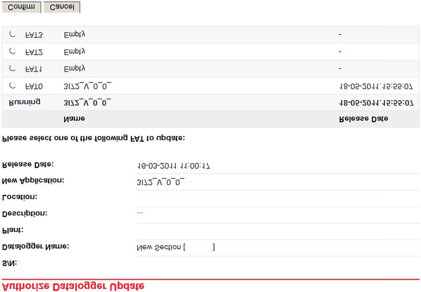
16- ENL. Firmware update via Web Portal
The firmware of the PVI-AEC-EVO can be updated via the Web Portal.
Each time a new firmware version is available, a warning will appear on the Web Portal pages indicating that a new
firmware is available.Moreover,users associated with the system will receive an e-mail notification.
To upgrade the firmware it is necessary to click on the link in the alert or on the link in the e-mail notification.
This will open a page where authorization is requested in order to proceed with the firmware update,and where the
location of memory (FAT) where to install the new firmware will be requested.
The maximum number of firmware versions that the memory can keep is 4 (FAT0,FAT1,FAT2,FAT3).
It is advisable to install the new version of the firmware into an empty memory location, or in the memory location
containing the oldest version of the firmware.
After selecting the desired memory location,click on 'Confirm' to proceed with the installation.
17 - ENEN - ENGLISH
Monitoring System
M. Firmware updating procedure via SD Card
The firmware update via SD card should be carried out only if it is not possible to update the firmware
viatheWebPortal.
1. Access the display by entering the user password 0000.
2. Check and note the current firmware versions installed:
Information > Product > Firmware AVR
Information > Product > Firmware Display
Information > Product > Firmware IO
3. Turn off the PVI-AEC-EVO and wait at least one minute.
4. Disconnect all available connections from the PVI-AEC-EVO (RS458 line(s),LAN connection,sensors).
5. Remove the SD Card from the slot on the PVI-AEC-EVO front panel by pressing the SD Card gently.
6. Insert the SD Card into the SD Card reader or into to the SD Card reader slot of the PC.
7. Delete the folders upgrade,web,lang and config from the SD Card.
8. Copy the new folders upgrade,web,lang and config into the root of the SD Card.
9. Remove the SD Card from the SD Card reader or from the SD Card reader slot.
10. Insert the SD Card into the slot on the PVI-AEC-EVO front panel by pressing the SD Card gently to lock it into place.
11. Turn on the PVI-AEC-EVO and wait about one minute.(N.B.: Power failure during update may cause serious damage
to the device).
12. Access the display by entering the administrator password 0010.
13. Access the menu Settings > Upgrade Firmware > Upgrade AVR. If the procedure was carried out correctly,the
system will to confirm the command by displaying the message“Are you sure?”.
14. Press ENTER to update the firmware.
15. Wait until the update (during the update the message “Waiting for Load” is displayed) and the reboot are
completed (during reboot the message “Waiting for Reboot”is displayed).The reboot is completed when date and
time are displayed.
16. Access the display by entering the administrator password 0010.
17. Access the menu Settings > Upgrade Config. The system will ask to confirm the command by displaying the
message“Are you sure?”.
18. Press ENTER to update the PVI-AEC-EVO configuration.
19. During the update the message “Waiting for Load” will be displayed. Wait until the configuration update is
completed. At the end of the update the menu Settings > Upgrade Config will be displayed.
20. Switch off the system,restore all connections (RS485 line(s),LAN connection,sensors),then switch on the system.
18- ENINDICE
A.
B.
C.
D.
E.
F.
G.
H.
I.
L.
M.
1 - ITMonitoring System
A. Descrizione del Prodotto
IT - ITALIANO
Il PVI-AEC-EVO è un sistema di monitoraggio e controllo degli impianti fotovoltaici realizzati con prodotti Power-
One Aurora.
Il prodotto consente l'acquisizione dei parametri da inverter e stringcomb (secondo l'architettura di monitoraggio
degli inverter centralizzati) attraverso linea RS485 con protocollo proprietario Power-One.
Il sistema dispone di due porte RS485 (equivalenti tra loro) che permettono l'acquisizione, ciascuna, di 62 inverter
di stringa o di 62 moduli di conversione da 55kW.
Il sistema dispone di tre ingressi analogici per il collegamento di sensori per la misura dei parametri ambientali:
Power-One offre,a catalogo,una gamma completa di sensori di irraggiamento,temperatura e velocità del vento.
Il sistema mette a disposizione anche sei ingressi digitali per l'acquisizione di segnali di stato (ad esempio contatti
ausiliari di interruttori di potenza) a cui sono associate condizioni di allarme di stato.
Relativamente all'interfaccia utente,il sistema dispone di un display 2x16 caratteri e quattro pulsanti oltre che di un
webserver integrato di pagine htm accessibile attraverso connessione LAN.
La configurazione iniziale del sistema (verifica dell'acquisizione dei parametri da inverter, configurazione degli
ingressi analogici, configurazione dei parametri di rete LAN) può essere eseguita interamente attraverso il display
ed i pulsanti; per la visualizzazione dei parametri di dettaglio degli inverter e/o delle stringcomb nonchè per le
configurazioni avanzate è necessario accedere alle pagine di webserver integrato.
Il PVI-AEC-EVO lavora in abbinamento ad un servizio di portale web: il sistema periodicamente trasmette i dati al
server di gestione del portale che presenta i dati in forma grafica su pagine web accessibili tramite account da
richiedere al customer service di Power-One.
Il portale è anche funzionale all'invio delle mail di allarme, di resoconto e di notifica di presenza di aggiornamenti
FW: l'aggiornamento del FW del sistema può essere effettuato direttamente da portale senza necessità
dell'intervento tecnico in loco.
Il FW può anche essere aggiornato localmente ovvero in assenza di connessione al portale.
2 - ITB. Interfaccia Utente ed utilizzo del display
Il sistema dispone di un display 2x16 caratteri, quattro pulsanti per la navigazione nei menù, e tre LED che indicano
lo stato del dispositivo.
Attraverso l’uso del display e dei pulsanti posti sul pannello frontale è possibile effettuare la configurazione iniziale
del sistema (verifica dell'acquisizione dei parametri da inverter, configurazione degli ingressi analogici,
configurazione dei parametri di rete LAN).
Per la visualizzazione dei parametri di dettaglio degli inverter e/o delle stringcomb nonchè per le configurazioni
avanzate è necessario accedere al webserver interno seguendo la procedura descritta nel paragrafo H.
Una lista delle funzioni accessibili da display è mostrata nella tabella presente in Appendice 3.
Power ON Alimentazione presente Alimentazione assente /
Bus ON Alimentazione del BUS di espansione Alimentazione assente del BUS di espansione /
Fault / / /
Pulsante “Enter”. Viene utilizzato per confermare un’ azione, per accedere al menù principale o al
sottomenù corrispondente alla voce selezionata (indicata dal simbolo >), o per passare alla cifra
successiva da modificare.
Pulsante “Down”. Viene utilizzato per scorrere le voci dei menù verso il basso, oppure per scorrere la
scala numerica in ordine decrescente.
Pulsante “Up”. Viene utilizzato per scorrere le voci dei menù verso l’alto, oppure per scorrere la scala
numerica in ordine crescente.
Pulsante“Esc”. Viene utilizzato per tornare al menù precedente o per tornare alla cifra precedente da
modificare.
Per poter effettuare le configurazioni iniziali, è necessario accedere come amministratore ai vari menù del display.
Premere il tasto“ENTER”( ) ed inserire la password : per inserire la password premere i tasti freccia ( )
per modificare il valore ed il tasto“ENTER”per confermare il valore. Attraverso questa password è possibile accedere a
tutti i sottomenu di impostazione del display.
3 - ITMonitoring System
C. Piedinatura dei connettori del sistema
IT - ITALIANO
Lo schema di seguito riporta la piedinatura dei connettori che permettono la connessione del sistema.
J5
RELAY
1) RELAY 1 J17 J15
2) RELAY 1_RTN RS485/1 RS485/2
3) RELAY 2 S2 1) RTN 1) RTN S1
4) RELAY 2_RTN
5) RELAY 3
J12 120Ω TERM. 2) - T/R 2) - T/R 120Ω TERM.
GROUND RS485/1 3) +T/R 3) +T/R RS485/2
6) RELAY 3_RTN 4) +5V 4) +5V
1 2 3 4 5 6 4 3 2 1 4 3 2 1
J9
EXPANSION
BUS
1 2 2 1 1 2 3 4 5 6 1 2 3 4 5 6 1 2 3 4 5 6
J7 J18 J8 J3 J20 J4
LAN BATTERY IN Vin DC ANALOG INPUT DIGITAL I/O DIGITAL I/O
IEEE802.3u 1) + Batt. 1) + Vcc PT100/1000 1) RTN 1 1) DIn 2
2) - Batt. 2) - Vcc 1) PT_ALIM 2) RTN 1 2) DIn 3
2) PT_SENSE 3) DO_PWM 2 3) DIn 4
NOTE: INPUT DC:
Only for dedicated 24 V DC 0,3 A 3) PT_RTN 4) DO_PWM 1 4) DIn_RTN
accessory NOTE:
4) AIn_RTN 5) DIn 1 5) DIn 5
PVI-BATTERY-PACK Use the provided 5) AIn 1 6) DIn_RTN 6) DIn 6
power supply 6) AIn 2
4 - ITD. Collegamenti di alimentazione del sistema
1. Collegare l'alimentatore alla rete di alimentazione (110/230V 50/60Hz):il led“Power”dell'alimentatore si accenderà
stabilmente. Verificare che la tensione di uscita dell'alimentatore sia 24Vdc. Scollegare l'alimentatore dalla rete di
alimentazione.
2. Collegare l'uscita dell'alimentatore alla morsettiera di alimentazione del PVI-AEC-EVO (rispettando la polarità)
utilizzando il cablaggio fornito a corredo.
3. Collegare l'alimentatore alla rete di alimentazione: dopo una prima fase di avvio (della durata di circa 30
secondi), durante la quale il sistema non è in grado di ricevere input da parte dell'utente, il led verde “Power ON”
rimarrà stabilmente acceso.A display sarà visibile la scritta“PVI-AEC-EVO....”(nella prima delle due righe) e data/ora
(nella seconda delle due righe).
+ + - -
Output DC
24V 0.75A
DC
OK
STEP POWER
Input AC
100-240V 2 1
L(+) N(-)
L(+) N(-) -Vcc +Vcc
50-60 Hz
100-240 V~
5 - ITMonitoring System
E. Impostazione di data ed ora
IT - ITALIANO
1. Accedere al menù principale come amministratore (Rif.Par.“B”).
2. Accedere al menu “SETTINGS” > “DATALOGGER” quindi selezionare il sottomenù “SET DATE”. Sarà possibile
impostare la data corretta nel sistema.
3. Ritornare al menù “DATALOGGER” , quindi selezionare il sottomenù “SET TIME”. Sarà possibile impostare l'ora
corretta nel sistema.
SET PIN TO 0010
PVI-AEC-EVO ...... menu pin
12.00.00 01/01/11 ENTER 0*** CHANGE VALUE
NEXT ENTER
DIGIT
>settings >datalogger
change password ENTER io settings ENTER
>set date >set date
set time ENTER 01/01/11 CHANGE VALUE
NEXT ENTER
FIELD
>set time >set time
network ENTER 12.00.00 CHANGE VALUE
NEXT ENTER
FIELD
F. Collegamenti della linea RS485 e verifica
dell’acquisizione degli inverter
Il collegamento della linea RS485 deve essere eseguito rispettando la piedinatura dei connettori J15 e/o J17. Si consiglia
di collegare la linea RS485 quando tutte le apparecchiature sono spente (sia il sistema di monitoraggio sia gli inverter) e di
mettere in servizio prima il sistema di monitoraggio e successivamente gli inverter. Si raccomanda di:
l Utilizzare un cavo per applicazioni RS485 avente le seguenti caratteristiche:1 coppia twistata + 1 conduttore oppure
due coppie twistate, Schermo ed Impedenza caratteristica pari a 120Ω. Per maggiori informazioni in merito ad il
cavo da utilizzare fare riferimento all’Appendice 2.
l Accertarsi della corrispondenza dei segnali.
l Accertarsi che tutte le tre linee (+T/R,-T/R e RTN) siano collegate in accordo agli schemi presenti nelle pagine 8 - 9.
l Accertarsi che lo schermo della linea di comunicazione sia riferito a terra in un solo punto (in accordo agli schemi nelle
pagine 8 - 9).
l Accertarsi che ogni elemento della catena (ovvero ogni inverter oppure ogni modulo da 55kW) abbia un indirizzo
RS485 differente rispetto agli altri. Tale indirizzo è impostabile attraverso il display dell’inverter.
6 - ITIn caso di collegamento di più unità (inverter di stringa o/e moduli di conversione da 55kW) è
necessario cablare la linea di comunicazione RS485 in accordo allo schema daisy-chain
(entra-esci).
L’ultimo inverter della catena daisy-chain deve essere “terminato” attivando la resistenza di
terminazione della linea di comunicazione da 120Ω, attraverso la commutazione del dip-switch
posto sulla scheda madre negli inverter di stringa, ed all’interno di ogni framework negli inverter
centralizzati.
Il numero massimo di unità (inverter di stringa o/e moduli di conversione da 55kW) collegabili ad
una porta RS485 del PVI-AEC-EVO è 62; per collegare un numero maggiore di 62 unità è necessario
utilizzare la seconda porta RS485/2 rispettando lo stesso schema di collegamento utilizzato per la
porta RS485/1 principale.
Nel caso di impianti misti, la compresenza di inverter di stringa e di inverter centralizzati sulla
stessa linea RS485 è permessa. Per cablare tale linea è necessario rispettare tutte le indicazioni
precedenti.
In tutti gli inverter (ad eccezione dei modelli PVI-5000/6000) è presente un morsetto chepermettedi
darecontinuitàalloschermodelcavodellalineaRS485.
Negli inverter monofase tale morsetto è indicato con la dicitura LNK,nei trifase è indicato con SCLD,nei
centralizzaticonX23.
Per ulteriori dettagli in merito alla cablatura della linea RS485 e/o all’attivazione delle resistenze
di terminazione, fare riferimento al manuale utente degli inverter di stringa e al manuale utente
degli inverter centralizzati.
7 - ITAccertarsi che ogni
inverter della catena abbia
un indirizzo RS485 differente
rispetto agli altri.
AURORA
AURORA
AURORA
OFF OFF OFF
ON ON ON
-T/R
-T/R
-T/R
RTN
RTN
RTN
+T/R
+T/R
+T/R
120Ω 120Ω 120Ω
Term. Term. Term.
RS485 Resistor RS485 Resistor RS485 Resistor
120Ω TERM.
RESISTOR ON
8 - IT
RTN
Monitoring System
+T/R
-T/R
OFF OFF
4 3 2 1 4 3 2 1
ON ON
RTN
RTN
-T/R
-T/R
+T/R
+T/R
120Ω TERM. 120Ω TERM.
RS485 RESISTOR RS485 RESISTOR
RTN +T/R -T/R RTN +T/R -T/R
120Ω TERM. 120Ω TERM.
RESISTOR ON RESISTOR OFF
IT - ITALIANO120Ω TERM. 120Ω TERM. 120Ω TERM.
RESISTOR ON RESISTOR OFF RESISTOR OFF Accertarsi che ogni
modulo da 55 kW della
catena abbia un indirizzo
RS485 differente rispetto agli
altri.
X20 X21 X22 X23 X24 X25 X26 X27 X20 X21 X22 X23 X24 X25 X26 X27 X20 X21 X22 X23 X24 X25 X26 X27
D D D
A A A
120Ω TERM.
RESISTOR ON
9 - IT
RTN
+T/R
-T/R
RTN +T/R -T/R RTN +T/R -T/R
4 3 2 1 4 3 2 1
D D
A A
X20 X21 X22 X23 X24 X25 X26 X27 X20 X21 X22 X23 X24 X25 X26 X27Monitoring System
Dopo aver effettuato queste verifiche, mettere in servizio prima il sistema di monitoraggio e successivamente gli
inverter. Il sistema effettua automaticamente la scansione del bus RS485 e quindi rileva in automatico gli inverter
IT - ITALIANO
presenti. Per verificare la presenza degli inverter,si può agire direttamente da display.
1. Accedere al menù principale come amministratore (Rif.Par.“B”).
2. Accedere al menu “CURRENT VALUES” > “ENERGY INVERTERS” (per visualizzare gli inverter di stringa) e/o
“CURRENT VALUES” > “ENERGY RACK” (per visualizzare i moduli di conversione da 55kW). Verrà visualizzato il
numero degli inverter individuati nella scansione; scorrendo con i tasti freccia ( ) sarà possibile
visualizzare la lista degli inverter monitorati identificati dal Serial Number (S/N).
SET PIN TO 0010
PVI-AEC-EVO ...... menu pin
12.00.00 01/01/11 ENTER 0*** CHANGE VALUE
NEXT ENTER
DIGIT
>CURRENT VALUE
SETTINGS ENTER
>ENERGY INVERTERS 30 INVERTERS
ENERGY RACK ENTER >INVERTER SN 123456 CHANGE
INVERTER
>ENERGY RACK RACK N. 1
ENERGY PLANT ENTER >RACK SN 123456 CHANGE
RACK
Il tempo impiegato dal PVI-AEC-EVO per effettuare la scansione ed acquisire gli inverter può variare
dipendentemente dal numero degli inverter presenti sulla stessa linea (talvolta alcuni minuti).
G. Configurazione degli ingressi analogici
Il collegamento dei sensori analogici deve essere effettuato rispettando la piedinatura del connettore J3.
Il sistema dispone di due ingressi di tipo 0-10 Vdc, ed un ingresso di tipo PT100/1000.
Per ogni ingresso analogico (sia del tipo 0-10 Vdc che PT100/1000) è possibile connettere un solo
sensore analogico. Non è quindi possibile connettere più sensori sullo stesso ingresso analogico.
Relativamente al collegamento di sensori del tipo PT100/1000, il sistema è in grado di effettuare la lettura dei
sensori attraverso il collegamento di tre fili:
l Una linea di alimentazione del sensore che funge anche come linea di Sense (PT_ALIM);
l Una linea di (ritorno della) lettura (PT_SENSE)
l Una linea di richiusura dell'alimentazione (PT_RTN).
10 - ITLa misura viene effettuata tra PT_ALIM (che come detto svolge anche funzione di Sense) e PT_SENSE; l'elemento di
misura deve essere cablato tra questi due segnali.
Il sensore PT100/PT1000 viene automaticamente riconoscuito dal sistema e quindi acquisito senza necessità di ulteriori
impostazioni.
In merito al collegamento dei sensori con range di uscita 0...10Vdc,questi devono essere alimentati e l'alimentazione può
essere prelevata direttamente dall'alimentazione del sistema; la massa dell'alimentazione e la massa di lettura dei
segnali è a comune.
Per il collegamento del sensore, oltre all'alimentazione, è necessario collegare il segnale proporzionale alla grandezza
misurata ad uno dei due ingressi analogici disponibili (AIn1/AIn2).
La massa del segnale di misura (qualora differente dalla massa dell'alimentazione (nella gamma dei sensori Power-One
solo nel sensore di velocità vento PVI-AEC-WIND-COMPACT)) deve essere deve essere collegata al morsetto AIn_RTN.
Dopo aver effettuato le connessioni è necessario configurare il sensore nel sistema in modo da acquisire correttamente la
grandezza:
1. Accedere al menù principale come amministratore (Rif.Par.“B”).
2. Accedere al menù “SETTINGS” > “IO SETTINGS”.
3. Selezionare la voce ANALOG INPUT1 e selezionare quindi il modello di sensore collegato all'ingresso AIn1 del sistema
(il modello selezionato verrà identificato con un asterisco (*) ).
4. Selezionare la voce ANALOG INPUT2 e selezionare quindi il modello di sensore collegato all'ingresso AIn2 del
sistema (il modello selezionato verrà identificato con un asterisco (*) ).
In caso di collegamento di sensori PT100/1000 con due soli terminali, collegare un terminale al
morsetto PT_SENSE ed un terminale al morsetto PT_RTN; realizzare poi un ponticello tra PT_ALIM
e PT_SENSE.
SET PIN TO 0010
PVI-AEC-EVO ...... menu pin
12.00.00 01/01/11 ENTER 0*** CHANGE VALUE
NEXT ENTER
DIGIT
>settings >io settings
change password ENTER UPGRADE FIRMWARE ENTER
>ANALOG INPUT1 >ANALOG INPUT1
ANALOG INPUT2 ENTER T1000-INTEGR * CHANGE ENTER
SENSORS
>ANALOG INPUT2 >ANALOG INPUT2
PULSE IN1 ENTER RAD-13TC * CHANGE ENTER
SENSORS
11 - ITMonitoring System
Per leggere le misure dei sensori e verificare la loro correttezza:
1. Accedere al menù principale come amministratore (Rif.Par.“B”).
IT - ITALIANO
2. Accedere al menu “CURRENT VALUES” > “ANALOG VALUE”. Verrà visualizzato il valore della grandezza per
ciascuno degli ingressi analogici.
SET PIN TO 0010
PVI-AEC-EVO ...... menu pin
12.00.00 01/01/11 ENTER 0*** CHANGE VALUE
NEXT ENTER
DIGIT
>CURRENT VALUE >ANALOG VALUE
SETTINGS ENTER DIGITAL VALUE ENTER
>T1000-INTEGR AN1
20.0 DEGC CHANGE
INPUT
MODELLO TIPOLOGIA IDENTIFICATIVO DISPLAY
2
PVI-AEC-IRR Sensore Irraggiamento (W/m --> V) IRR
PVI-AEC-IRR-T Sensore Irraggiamento con sensore Temperatura IRR-T_Irr / IRR-T_Temp
cella integrato (W/m2 / °C --> V)
2
PVI-AEC-RAD-13TC Sensore Irraggiamento (W/m --> V) RAD-13TC
PVI-AEC-RAD-13TC-T Sensore Irraggiamento con sensore Temperatura RAD-13-TC-T_Irr /
2
cella integrato (W/m / °C --> V) RAD-13-TC-T_Temp
PVI-AEC-CONV-T100 Sensore PT100 collegato a convertitore T100-ADH-CONV /
PT100/0...10Vdc (°C --> V) T100-BOX-CONV
PVI-AEC-T1000-INTEGR Sensore di temperatura ambiente con T1000-INTEGR
convertitore 0...10Vdc integrato (°C --> V)
PVI-AEC-T100-ADH Sensore di temperatura modulo (back cell) T100-ADH
PT100 adesivo
PVI-AEC-T100-BOX Sensore di temperatura ambiente PT100 T100-BOX
PVI-AEC-T1000-BOX Sensore di temperatura ambiente PT1000 T1000-BOX
PVI-AEC-WIND-COMPACT Sensore velocità vento (m/s --> V) WIND-COMPACT
PVI-AEC-WIND-DIR Sensore direzione vento (° --> V) WIND-DIR
Per la connessione dei sensori sopra indicati fare riferimento agli schemi presenti in Appendice 1.
12 - ITH. Configurazione del sistema per la connessione
in rete LAN (porta Ethernet)
1. Alimentare il sistema ed attendere il completamento della fase di avvio (Rif.Par.”D”).
2. Accedere al menù principale come amministratore (Rif.Par.“B”).
3. Accedere al menù “SETTINGS” > “NETWORK”. Attraverso le voci del menu “NETWORK” sarà possibile
modificare i parametri di connessione alla rete LAN (Indirizzo IP, Subnet Mask, Gateway) in modo da
configurare il sistema per la connessione in rete e/o per la connessione diretta ad un PC/Laptop.
4. Al termine delle operazioni di impostazione,ritornare alla schermata principale,quindi spegnere e riaccendere
il sistema per rendere effettive le impostazioni.
SET PIN TO 0010
PVI-AEC-EVO ...... menu pin
12.00.00 01/01/11 ENTER 0*** CHANGE VALUE
NEXT ENTER
DIGIT
>settings >datalogger
change password ENTER io settings ENTER
>NETWORK
SET DATA ENTER
>IP method >IP method
ip setting ENTER manual CHANGE ENTER
METHOD
>IP SETTING >IP SETTING
SUBNET MASK ENTER 10.200. 4. 51 CHANGE VALUE
NEXT ENTER
DIGIT
>SUBNET MASK >subnet mask
ip gateway ENTER 255.255. 0. 0 CHANGE VALUE
NEXT ENTER
DIGIT
>IP gateway >IP gateway
ip method ENTER 10.200. 1. 1 CHANGE VALUE
NEXT ENTER
DIGIT
13 - ITMonitoring System
5. Al nuovo riavvio le pagine di webserver del sistema saranno accessibili attraverso connessione Ethernet
(diretta con PC/Laptop oppure attraverso rete LAN) utilizzando l'indirizzo IP impostato. Per accedere alle
IT - ITALIANO
pagine di webserver del sistema, dopo aver effettuato la connessione del sistema in rete LAN (cavo Ethernet
patch) oppure diretta a PC/Laptop (cavo Ethernet cross), aprire un browser internet (es. Internet Explorer) e
digitare nella barra degli indirizzi: http://
6. Per accedere alle pagine di webserver è necessario inserire username e password:
7. Accedere alla pagina di configurazione (CONFIG) dell'impianto (PLANT) ed inserire le coordinate GPS
dell'installazione secondo uno dei seguenti formati:
*
14 - IT8. Accedere alla pagina di configurazione (CONFIG) della rete (NETWORK) e verificare che nella sezione
“DATATRANSFER”alla voce“Ip Address Portal”si trovi l’indirizzo IP 151.22.100.44 .
Qualora l’impostazione “Ip Portal Address” non corrisponda a 151.22.100.44 , modificarla
immettendo tale indirizzo e premere su “Confirm” per renderla attiva. Successivamente a questa
operazione,effettuare il reset del sistema (ON-OFF).
Per rendere completamente funzionante il sistema è indispensabile che il sistema stesso sia
continuativamente connesso ad internet in modo da poter dialogare con il server di Power-One per
le operazioni di visualizzazione grafica dei dati su pagine web oltre che per l'invio di messaggi di
allarme e/o di report. Affinchè il PVI-AEC-EVO sia in grado di dialogare con il server di gestione del
portale,è indispensabile che la rete LAN nella quale il PVI-AEC-EVO è cablato sia tale da permettere
la connessione all'indirizzo IP 151.22.100.44 attraverso la porta 80.
15 - ITMonitoring System
I. Modulo di richiesta nuovo impianto su Portale Web
IT - ITALIANO
(utilizzati per la visualizzazione del contatto)
(utilizzato per l’accesso al portale)
(utilizzato per l’accesso al portale - almeno 8
caratteri)
(utilizzato per l’invio di messaggi di allarme e/o
di report a seconda della configurazione
personalizzata a carico dell’utente)
(Visibile sull’etichetta del PVI-AEC-EVO)
(utilizzato per la creazione dell’impianto
associato al/ai PVI-AEC-EVO)
(Necessaria per l’impostazione delle coordinate
GPS - Se disponibili, inserire anche latitudine e
longitudine dell’impianto)
l Ilmodulodeveessereinviato SOLODOPO averpredispostolaconnessioneadinternetdelPVI-AEC-EVO.
l Nel caso si voglia richiedere l'attivazione di portali associati a più PVI-AEC-EVO installati in
differenti impianti,è necessario compilare un modulo per ciascun impianto.
l Ilnuovoaccountcheverracreatopossiederàiprivilegidiamministrazionesull’impiantoadessoassociato.
l L'account amministratore ha la possibilità di modificare le impostazioni del portale e creare
ulteriori account con credenziali di accesso utente.
l L'account utente ha solo la possibilità di visualizzare i dati dell'impianto.
l Per l'accesso al portale è necessario collegarsi al sito:
http://151.22.100.44/aurora
ed utilizzare le credenziali indicate nella tabella di cui sopra.
16 - ITL. Aggiornamento Firmware attraverso Portale Web
Attraverso il Portale Web è possibile effettuare l’aggiornamento del firmware del PVI-AEC-EVO.
Ogni volta che una nuova versione del firmware sarà disponibile, sulle pagine del Portale Web apparirà un avviso che
indica la presenza del nuovo firmware; verrà inoltre inviata una e-mail di notifica agli utenti associati all’impianto.
Per eseguire l’aggiornamento del firmware è necessario cliccare sul link presente sull’avviso o sul link presente nella
e-mail di notifica.
Si aprirà una pagina dove verrà richiesta l’autorizzazione per procedere con l’aggiornamento del firmware e dove verrà
richiesta la posizione di memoria (FAT) dove installare il nuovo firmware.
Il numero massimo di versioni firmware che è possibile mantenere in memoria è 4 (FAT0,FAT1,FAT2,FAT3).
Si consiglia di installare la nuova versione del firmware in una posizione di memoria vuota, oppure nella posizione di
memoria contenente la versione del firmware meno recente.
Dopo aver selezionato la posizione di memoria desiderata,cliccare su“Conferma”per procedere con l’installazione.
17 - ITMonitoring System
M. Procedura di aggiornamento Firmware attraverso SD Card
IT - ITALIANO
L’aggiornamento del firmware attraverso SD Card deve essere effettuato solo nel caso in cui non sia
possibile effettuare l’aggiornamento del firmware attraverso Portale Web.
1. Accedere al display inserendo la password di utente 0000.
2. Verificare e annotare la versione correntemente installata dei firmware:
Information > Product > Firmware AVR
Information > Product > Firmware Display
Information > Product > Firmware IO
3. Spegnere il PVI-AEC-EVO e attendere almeno un minuto.
4. Disconnettere dal PVI-AEC-EVO tutte le connessioni presenti (Linea/e RS485,connessione LAN,sensori).
5. Estrarre la SD Card dallo slot posto sul pannello frontale del PVI-AEC-EVO esercitando una leggera
pressione sulla SD Card.
6. Inserire la SD Card nel lettore di SD Card oppure nello slot per lettura della SD Card del PC
7. Eliminare le cartelle upgrade,web,lang e config dalla SD Card.
8. Copiare nella radice della SD Card le nuove cartelle upgrade,web,lang e config.
9. Estrarre la SD Card dal lettore di SD Card oppure dallo slot per la lettura di SD Card.
10. Inserire la SD Card nell'apposito slot posto sul pannello frontale del PVI-AEC-EVO esercitando una
leggera pressione sulla SD Card in modo da favorirne il bloccaggio.
11. Accendere il PVI-AEC-EVO e attendere circa un minuto.(N.B. l’interruzione dell’alimentazione durante la fase di
aggiornamento può provocare gravi danni al dispositivo).
12. Accedere al display inserendo la password di amministratore 0010.
13. Accedere al menu Settings > Upgrade Firmware > Upgrade AVR. Se la procedura è stata correttamente
eseguita,verrà richiesto,attraverso il messaggio“Are you sure?”,di confermare il comando.
14. Premere ENTER per aggiornare il firmware.
15. Attendere il completamento dell'aggiornamento (durante l'aggiornamento sarà visualizzato il
messaggio “Waiting for Load”) e il completamento del riavvio (durante il riavvio sarà visualizzato il
messaggio “Waiting for Reboot”). Il processo di riavvio sarà completato quando sul display sarà
visualizzata la data e l'ora.
16. Accedere al display inserendo la password di amministratore 0010.
17. Accedere al menu Settings > Upgrade Config. Verrà richiesto, attraverso il messaggio “Are you sure?”, di
confermare il comando.
18. Premere ENTER per aggiornare la configurazione del PVI-AEC-EVO.
19. Durante l'aggiornamento sarà visualizzato il messaggio “Waiting for Load”. Attendere il completamento
dell'aggiornamento della configurazione. Al termine dell'aggiornamento sarà visualizzato il menu
Settings > Upgrade Config.
20. Spegnere il sistema, ripristinare tutte le connessioni (Linea/e RS485, connessione LAN, sensori), quindi
accendere il sistema.
18 - ITINHALTSVERZEICHNIS
A.
B.
C.
D.
E.
F.
G.
H.
I.
L.
M.
1 - DEMonitoring System
A. Beschreibung des Produkts
Beim PVI-AEC-EVO handelt es sich um ein Überwachungs- und Kontrollsystem für Photovoltaikanlagen, die mit
Produkten Power-One Aurora errichtet wurden.
Mit dem Produkt können die Parameter von Wechselrichtern und Stringcombs (je nach Aufbau der Überwachung der
zentralisiertenWechselrichter) über die Leitung RS485 mit dem proprietären Protokoll von Power-One erfasst werden.
DE - DEUTSCH
Das System verfügt über zwei gleichwertige Ports RS485,mit denen jeweils eine Erfassung von 62 String-Wechselrichtern
oder 62Wandlungsmodulen mit 55kW möglich ist.
Das System verfügt über drei Analogeingänge für den Anschluss von Sensoren für die Messung der Umweltparameter:
Power‐One bietet in seinem Katalog ein komplettes Angebot von Sensoren für Sonneneinstrahlung, Temperatur und
Windgeschwindigkeit an.
Das System umfasst auch sechs Digitaleingänge für die Erfassung von Statussignalen (beispielsweise Hilfskontakte von
Leistungsschaltern),denen die Status-Alarmbedingungen zugeordnet sind.
Als Benutzerschnittstelle bietet das System ein Display mit 2x16 Zeichen und vier Tasten sowie einen integrierten
Internetserver mit htm-Seiten über eine LAN-Verbindung.
Die Anfangskonfiguration des Systems (Überprüfung der Erfassung der Parameter von Wechselrichtern, Konfiguration
der Analogeingänge,Konfiguration der Parameter des LAN-Netzwerks) kann vollständig über das Display und dieTasten
vorgenommen werden;Für die Anzeige der Detail-Parameter derWechselrichter und/oder der Anschlusskasten sowie für
die erweiterten Konfigurationen ist die Öffnung der Seiten des integrierten Internet-Servers erforderlich.
Das PVI-AEC-EVO arbeitet über ein kostenloses Internetportal: das System überträgt regelmäßig Daten an den
Steuerserver des Portals und präsentiert die Daten in graphischer Form in Webseiten, die über den Account geöffnet
werden können.Dieser muss beim Kundendienst von Power-One angefordert werden.
Über das Portal können auch Alarm-Mails,Bericht-Mails und Mitteilungen zumVorhandensein von FW-Aktualisierungen
verschickt werden. Die Aktualisierung der FW des Systems kann direkt über das Portal erfolgen, ohne dass ein Eingriff
einesTechnikers vor Ort erforderlich ist.
Die FW kann auch vor Ort,d.h.ohneVerbindung mit dem Portal aktualisiert werden.
2 - DEB. Benutzerschnittstelle und Verwendung des Displays
Das System verfügt über ein Display mit 2x16 Zeichen, vier Tasten zum Navigieren in den Menüs und drei LEDs zur
Statusanzeige des Geräts.
Die Anfangskonfiguration des Systems (Überprüfung der Erfassung der Parameter von Wechselrichtern, Konfiguration
der Analogeingänge, Konfiguration der Parameter des LAN-Netzwerks) kann über das Display und die Tasten an der
Frontabdeckung vorgenommen werden.
Für die Anzeige der Detail-Parameter der Wechselrichter und/oder der Anschlusskasten sowie für die erweiterten
Konfigurationen ist der Zugang zum internen Internet-Server erforderlich.Dabei sind die im Abschnitt H beschriebenen
Schritte auszuführen.
Eine Liste der über das Display zugänglichen Funktionen ist in derTabelle im Anhang 3 aufgeführt.
Power ON Vorhauden Leistung Vorhauden nich Leistung /
Bus ON Versorgung Erweiterungsbus vorhanden Versorgung Erweiterungsbus nicht vorhanden /
Fault / / /
Taste "Enter". Diese Taste wird verwendet, um eine Aktion zu bestätigen, um ins Hauptmenü oder in
das Untermenü eines der ausgewählten Menüpunkte (durch das Symbol > angezeigt) zu gelangen
oder um zur folgenden Ziffer die zu ändern ist zu springen.
Taste "Down". Diese Taste wird verwendet, um die Menüpunkte nach unten zu scrollen oder um die
numerische Skala absteigend zu sortieren.
Taste "Up". Diese Taste wird verwendet, um die Menüpunkte nach oben zu scrollen oder um die
numerische Skala aufsteigend zu sortieren.
Taste "Esc". Diese Taste wird verwendet, um in das vorherige Menü zu gelangen oder um zur
vorgehenden Ziffer,die zu ändern ist,zurückzukehren.
Um die Anfangskonfigurationen vorzunehmen, wir der Zugang als Administrator zu den verschiedenen Menüs
benötigt. Die Taste“ENTER”( ) drücken und das Passwort 0010 eingeben: Für die Eingabe des Passworts die
Pfeiltasten ( ) drücken,um den Wert zu ändern,dann die Taste“ENTER”drücken,um den Wert zu bestätigen.
Mit diesem Passwort ist der Zugriff auf alle Einstellung-Untermenüs des Displays möglich.
3 - DEMonitoring System
C. Pinbelegung der Systemstecker
Im nachfolgend aufgeführten Schema werden die Pin-out der Stecker gezeigt, mit denen das System
angeschlossen wird.
DE - DEUTSCH
J5
RELAY
1) RELAY 1 J17 J15
2) RELAY 1_RTN RS485/1 RS485/2
3) RELAY 2 S2 1) RTN 1) RTN S1
4) RELAY 2_RTN
5) RELAY 3
J12 120Ω TERM. 2) - T/R 2) - T/R 120Ω TERM.
GROUND RS485/1 3) +T/R 3) +T/R RS485/2
6) RELAY 3_RTN 4) +5V 4) +5V
1 2 3 4 5 6 4 3 2 1 4 3 2 1
J9
EXPANSION
BUS
1 2 2 1 1 2 3 4 5 6 1 2 3 4 5 6 1 2 3 4 5 6
J7 J18 J8 J3 J20 J4
LAN BATTERY IN Vin DC ANALOG INPUT DIGITAL I/O DIGITAL I/O
IEEE802.3u 1) + Batt. 1) + Vcc PT100/1000 1) RTN 1 1) DIn 2
2) - Batt. 2) - Vcc 1) PT_ALIM 2) RTN 1 2) DIn 3
2) PT_SENSE 3) DO_PWM 2 3) DIn 4
NOTE: INPUT DC:
Only for dedicated 24 V DC 0,3 A 3) PT_RTN 4) DO_PWM 1 4) DIn_RTN
accessory NOTE:
4) AIn_RTN 5) DIn 1 5) DIn 5
PVI-BATTERY-PACK Use the provided 5) AIn 1 6) DIn_RTN 6) DIn 6
power supply 6) AIn 2
4 - DEYou can also read