WNI410/411 Series Electroless Nickel Controller Instruction Manual
←
→
Page content transcription
If your browser does not render page correctly, please read the page content below
W A L C H E M
IWAKI America Inc.

WNI410/411 Electroless Nickel Controllers

                                          WNI410/411 Series
                                 Electroless Nickel Controller
                                           Instruction Manual

                     Five Boynton Road Hopping Brook Park Holliston, MA 01746 USA
                     TEL: 508-429-1110 FAX: 508-429-7433 WEB: www.walchem.com
Notice
© 2014 WALCHEM, Iwaki America Inc.(hereinafter “Walchem”)
5 Boynton Road, Holliston, MA 01746 USA
(508) 429-1110
All Rights Reserved
Printed in USA
Proprietary Material
The information and descriptions contained herein are the property of WALCHEM. Such information
and descriptions may not be copied or reproduced by any means, or disseminated or distributed without
the express prior written permission of WALCHEM, 5 Boynton Road, Holliston, MA 01746.
This document is for information purposes only and is subject to change without notice.
Statement of Limited Warranty
WALCHEM warrants equipment of its manufacture, and bearing its identification to be free from
defects in workmanship and material for a period of 24 months for electronics and 12 months for
mechanical parts and electrodes from date of delivery from the factory or authorized distributor under
normal use and service and otherwise when such equipment is used in accordance with instructions
furnished by WALCHEM and for the purposes disclosed in writing at the time of purchase, if any.
WALCHEM’s liability under this warranty shall be limited to replacement or repair, F.O.B. Holliston,
MA U.S.A. of any defective equipment or part which, having been returned to WALCHEM,
transportation charges prepaid, has been inspected and determined by WALCHEM to be defective.
Replaceable elastomeric parts and glass components are expendable and are not covered by any
warranty.
THIS WARRANTY IS IN LIEU OF ANY OTHER WARRANTY, EITHER EXPRESS OR IMPLIED, AS
TO DESCRIPTION, QUALITY, MERCHANTABILITY, FITNESS FOR ANY PARTICULAR PURPOSE
OR USE, OR ANY OTHER MATTER..
180366.G
July 2014TABLE OF CONTENTS 1.0 INTRODUCTION........................................................................................................................ 1 2.0 SPECIFICATIONS ..................................................................................................................... 2 2.1 Measurement Performance ................................................................................................................... 2 2.2 Electrical: Input/Output .......................................................................................................................... 2 2.3 Mechanical ............................................................................................................................................. 2 2.4 WNI Variables and their Limits .............................................................................................................. 3 3.0 UNPACKING & INSTALLATION ................................................................................................ 4 3.1 Unpacking the unit ................................................................................................................................. 4 3.2 Mounting the electronic enclosure ......................................................................................................... 4 3.3 Flow Through Nickel Sensor/Sample Loop Installation ......................................................................... 4 3.4 Icon Definitions .................................................................................................................................... 10 3.5 Electrical installation ............................................................................................................................ 10 4.0 FUNCTION OVERVIEW .......................................................................................................... 14 4.1 Front Panel .......................................................................................................................................... 14 4.2 Display ................................................................................................................................................. 14 4.3 Keypad ................................................................................................................................................. 15 4.4 Access Code ........................................................................................................................................ 15 4.5 Startup ................................................................................................................................................. 15 4.6 Shut Down ........................................................................................................................................... 16 5.0 OPERATION ............................................................................................................................ 17 5.1 Main Menu ........................................................................................................................................... 17 5.2 Sensor Menu........................................................................................................................................ 19 5.3 pH Input Menu ..................................................................................................................................... 21 5.4 Temperature Menu .............................................................................................................................. 23 5.5 Output 1 Menu ..................................................................................................................................... 24 5.6 Output 2 and 3 Menus ........................................................................................................................ 27 5.7 pH Output (Output 3) Menu ................................................................................................................. 29 5.8 Output 4 and Alarm Menus .................................................................................................................. 32 5.9 4-20 mA 1 and 2 Menus (Optional)...................................................................................................... 36 5.10 Time Menu ........................................................................................................................................... 37 5.11 Access Code Menu .............................................................................................................................. 38 5.12 Datalog Menu....................................................................................................................................... 39 5.13 Config Menu......................................................................................................................................... 41 5.14 Upgrade Menu ..................................................................................................................................... 43 6.0 MAINTENANCE ....................................................................................................................... 44 6.1 Nickel Sensor Cleaning ....................................................................................................................... 44 6.2 pH Electrode Maintenance .................................................................................................................. 44 6.3 Replacing the Fuses ............................................................................................................................ 45 7.0 TROUBLESHOOTING ............................................................................................................. 46 7.1 Error Messages.................................................................................................................................... 46 8.0 SERVICE POLICY ................................................................................................................... 50
1.0   INTRODUCTION

      The WNI410 series nickel controllers are optoelectronic on-line analyzers that may be used in variety of
      applications including electroless nickel baths and a number of other chemistries that contain more than
      0.10 grams/liter (g/L) of nickel ions. Because the sensors are made with glass, do not use these
      controllers in baths that contain fluorides.

      Four control relays are available that may be set up to feed chemicals, or as alarms. A fifth relay is used
      as a diagnostic alarm. Output 3 may be used for pH control if the optional pH input board is installed.
      One or two isolated 4-20 mA outputs that are proportional to the nickel concentration are optional.

      Any set point may be viewed without interrupting control. Each set point change will take effect as soon
      as it is entered. An access code is available to protect set point parameters, while still allowing settings
      to be viewed.

      Our unique USB feature provides the ability to upgrade the software in the controller to the latest
      version.

      An advanced USB capability option is available. The Configuration file feature allows you to save all
      the set points from a controller onto a USB flash disk, and then import them into another controller,
      making the programming of multiple controllers fast and easy. The data logging feature allows you to
      save the last 2 month’s readings and events to a USB flash disk.

                                                       1
2.0 SPECIFICATIONS
2.1 Measurement Performance
Electroless Nickel Concentration Range 0.1 - 25 g/L (0.01 – 3.32 oz/gal)
Nickel Concentration Resolution 0.001 g/L (0.0001 oz/gal)
Nickel Concentration Accuracy ±0.01 g/L (0.001 oz/gal)
Optional pH Input Range 0 – 14 pH
Optional pH Resolution 0.01 pH
Optional pH Accuracy Electrode and calibration dependant
Optional pH Automatic Temperature Compensation Pt100 or Pt1000
Temperature Range 0-100°C (32-212°F)
Temperature Resolution 0.05°C (0.09°F)
Temperature Accuracy ±0.1°C (±0.18°F)
2.2 Electrical: Input/Output
Input Power 100-240 VAC, 50/60 Hz, 8A
Fuse: 1.0 ampere, 5 x 20 mm
Input Signals
Nickel Sensor Signal 0 to 2VDC
pH (optional) ±500 mV
Interlock (optional) Isolated, dry contact closure required (i.e., flow, level, etc.)
Outputs
Mechanical Relays (5) Internally powered relays switching line voltage
6 A (resistive), 1/8 HP
All relays are fused together as one group, total current for this
group must not exceed 6A
Note: The Alarm relay is non-programmable as to responding to diagnostic alarms. Refer to the Main
Menu diagram for the list of error conditions that trigger the alarm relay.
4 - 20 mA (1 or 2 optional) Internally powered
Fully isolated
600 Ohm max resistive load
Resolution .001% of span
Accuracy ± 1% of reading
Nickel Sensor Power + 5VDC, 150 mA
Optional pH Sensor Power ±5V DC, 5 mA
Agency Approvals
Safety UL 61010-1:2012 3rd Ed.
CSA C22.2 No. 61010-1:2012 3rd Ed.
IEC 61010-1:2010 3rd Ed.
EN 61010-1:2010 3rd Ed.
EMC IEC 61326-1:2005
EN 61326-1:2006
Note: For EN61000-4-6, EN61000-4-3 the controller met performance criteria B.
*Class A equipment: Equipment suitable for use in establishments other than domestic, and those directly
connected to a low voltage (100-240 VAC) power supply network which supplies buildings used for
domestic purposes.
2.3 Mechanical
Controller Specifications
Enclosure Material Polycarbonate
NEMA Rating NEMA 4X
Dimensions 8.5" x 6.5" x 5.5"
Display 2 x 16 character backlit liquid crystal
Operating Ambient Temp 32 – 122°F (0 – 50°C)
Storage Temperature -20 – 180°F (-29 – 80°C)
2Sensor Specifications
Enclosure ABS
Wetted Materials: Polyethylene, glass, FKM
Dimensions: 6.75" x 4.75" x 2.25"
Operating Ambient Temperature 32 - 122°F (0 - 50°C)
Storage Temperature: -40 to 185°F (-40 to 85°C)
Solution Temperature: 200°F (93°C) max.
Maximum Cable Length 80 feet (25 meters)
2.4 WNI Variables and their Limits
Low Limit High Limit
Sensor menu
Days Between Calibration 0 days (no reminder) 59 days
1 Point Calibration Offset ± 0.01 g/l, 0.001 oz/gal ± 0.45 g/l, 0.045 oz/gal
pH Input Menu (WNI411 only)
Days Between Calibration 0 days (no reminder) 59 days
1 Point Calibration Offset ± 0.01 pH ± 0.99pH
Temperature Menu (WNI411 only) No variables
Output 1 -4 Menus
Set Point 0 (units set by user) 99.99 g/l, 9.999 oz/gal
High or Low Alarm Point 0 (units set by user) 99.99 g/l, 9.999 oz/gal
Dead Band 0 (units set by user) 2.01 g/l, 0.201 oz/gal
Time Limit (set in min:sec) 0:01 59:59 (enabled)
0=unlimited (disabled)
Pump Rate 0.01 (units set by user) 100.01 (units set by user)
Turnover Limit 1 metal turnover 99 metal turnovers
Turnover Volume 1 (units set by user) 9999 (units set by user)
pH Output Menu (WNI411 only)
High or Low Set Point 0.01 pH 14.00 pH
Dead Band 0.01 pH 1.99 pH
Time Limit (set in min:sec) 0:01 59:59 (enabled)
0=unlimited (disabled)
Alarm Menu
High or Low Alarm Point 0 (units set by user) 99.99 g/l, 9.999 oz/gal
Dead Band 0 (units set by user) 2.01 g/l, 0.201 oz/gal
Time Limit (set in min:sec) 0:01 59:59 (enabled)
0=unlimited (disabled)
4-20 mA_1 or 2 Menus
4 & 20 mA Settings, Ni 0 (units set by user) 99.99 g/l, 9.999 oz/gal
4 & 20 mA Settings, pH (WNI411 only) 0 pH 14 pH
Access Code Menu
New Value 0 9999
Datalog Menu (Optional) No variables
Config Menu (Optional) No variables
Upgrade Menu No variables
*Note: The Alarm relay is non-programmable as to responding to diagnostic errors. Refer to the Main Menu
diagram for the list of error conditions that trigger the alarm relay.
33.0 UNPACKING & INSTALLATION
3.1 Unpacking the unit
Inspect the contents of the carton. Please notify the carrier immediately if there are any signs of damage
to the controller or its parts. Contact your distributor if any of the parts are missing. The carton should
contain: a WNI series controller and instruction manual. Any options or accessories will be incorporated
as ordered.
3.2 Mounting the electronic enclosure
The WNI series controller is supplied with mounting holes on the enclosure. It should be wall mounted
with the display at eye level, on a vibration-free surface, utilizing all four mounting holes for maximum
stability. Use M6 (1/4" diameter) fasteners that are appropriate for the substrate material of the wall.
The enclosure is NEMA 4X rated. The maximum operating ambient temperature is 122°F (50°C); this
should be considered if installation is in a high temperature location. The enclosure requires the
following clearances:
Top: 2" (50 mm)
Left: 8" (203 mm)
Right: 4" (102 mm)
Bottom: 7" (178 mm)
3.3 Flow Through Nickel Sensor/Sample Loop Installation
The nickel flow through sensor is designed for out-of-tank monitoring of electroless nickel solutions.
The sensor is designed with a glass tube that contains the nickel solution that forms a fixed path length
between the lamp and receptor module. The solution absorbs light at specific wavelengths in proportion
to the nickel concentration. In order to avoid a shift in calibration caused by condensation, the sensor
cover should NEVER be removed!
The flow through sensor is provided with a mounting plate and 20 feet of cable. Extension cable is
available if the sensor cannot be placed within 20 feet of the controller. The maximum cable length is
80 feet. Always route AC voltage wiring in conduit that is separated a minimum of 6 inches from low
voltage DC signal lines (such as the sensor signal).
The sample loop consists of a shut off valve, a cooling coil or plate, a sensor, an optional pH adapter
assembly, a pump, or any combination thereof. The shut off valve is to quickly isolate the system if
necessary. A cooling coil or plate is necessary to cool the nickel solution down to a temperature
acceptable to a sample pump and/or pH electrode (if applicable). Cooling the solution is also
recommended to help reduce the amount of plate-out that may form in the sample loop. The pH adapter
assembly is used to mount an in-line pH electrode. It should be mounted such that the electrode is
always immersed in the 'U' trap. The pump may be either a stand-alone sample pump (which will
typically have high temperature restrictions), or a high temperature pump (which is usually a branch off
of the recirculation pump).
The flow through sensor/sample loop must be installed according to the following guidelines:
Mount the sensor on a vibration-free, vertical surface so that the sensor tubing inlet
connection is at the bottom and the outlet is at the top. The vertical orientation will prevent
air bubbles from being trapped in the sensor.
Install a shut-off valve at the beginning of the sample loop so that the system may be shut
off quickly if necessary.
4 If a sample pump is to be used, it must be installed last, after the cooling coil or cooling
plate, the flow through sensor, and the pH adapter assembly, if applicable.
If a high temperature recirculation pump is to supply flow, adjust flow rate through the
sample loop between 400 - 500 mL/min (approx. 0.11 - 0.13 gal/min). This flow rate will
help ensure adequate cooling of the solution while maintaining a reasonable lagtime in
longer runs of tubing. If this is not possible or is undesirable, see Application Notes below.
Other installation guidelines that may be helpful in the overall system:
Mount the sensor as close to solution as possible. Keep tubing distances to the sensor inlet
as short as possible to avoid hydraulic lag time. Maximum recommended length of tubing
from solution to sensor is 25 feet. If this is not possible, see Application Notes below.
The solution inlet should draw sample from an area of good solution movement in order to
respond quickly to chemical additions. However, the solution inlet should not draw too near
to where the chemistry is added to avoid artificial 'spikes' in concentration.
The solution discharge should be open to atmospheric pressure in order to ensure proper
flow.
The cable connector to the controller is keyed, do not force!
Application Notes
If the distance from the solution to the sensor is further than the recommended length of 25 feet, the
maximum lagtime must be calculated from the desired control band to determine a pump flow rate
based on a given distance of standard, uniform tubing. The maximum lagtime is the maximum
allowable time for the solution to continuously get to the sensor in order to achieve the desired control
band.
To calculate maximum lagtime:
Max. Lagtime = Desired Control Band*
4 x Depletion Rate
where Control band = Maximum deviation of concentration
Depletion rate = Rate at which the bath will deplete per unit of time
The deadband should be adjusted so that it is 1/4 the desired control band.
For Example: The set point is 4.00 g/L.
If the desired control band is 0.20 g/L (± 0.10 g/L or 2.5%) and the bath is depleting at a rate of 1.25 g/L
every 15 minutes (0.08333 g/L every minute),
then Max. Lagtime = 0.20 g/L = 0.60 minutes
4 x (0.08333 g/L /min)
So, 0.60 minutes is the maximum time it should take for the solution to reach the sensor.
To calculate pump flow rate:
5Minimum Pump Flow Rate = Volume of System*
Maximum Lagtime
where Volume of system = ( Tubing I.D.) 2 x Length of tubing
2
Maximum lagtime = Previously calculated time to get solution to sensor.
* Volume is based on length from solution to sensor, not the return.
For Example: If the system parameters are: Tubing is 3/8" O.D. ' 1/4" I.D.
Length is 30 feet (360 inches)
then the volume of the system = ( 0.25 in )2 x (360 in)
2
= 17.7 in3
Note: 1 U.S. Gallon = 231 U.S cubic inches 1 Liter = 61.03 U.S. cubic inches
Volume of Cooling Coil: 0.018 Gallons Volume of Cooling Plate: 0.023 Gallons
0.068 Liters 0.088 Liters
Volume of 3/8" O.D. x 1/4" I.D. (0.59 in3/ft): 0.00255 Gallons/linear ft
0.00965 Liters/linear ft
Volume of the system = 17.7 in3 = 0.0765 gallons
231 in3 / gallon
Maximum lagtime = 0.60 minutes (previously calculated)
So, the minimum pump flow rate = 0.0765 gallons = 0.127gal/min (483 mL/min)
0.60 minutes
Caution: The calculated pump flow rate is the minimum required to obtain the desired control band, however, if
the flow rate increases over the recommended rate of 500 mL/min (approx. 0.13 gal/min) the rate of cooling will
decrease. This may be compensated for by re-evaluating the system criteria: length / desired control band or to
double up on the cooling plate/coil.
Consult factory with any further installation questions.
6Installation including degasser
pH ELECTRODE
Back to the bath
Shut-off valve pH ADAPTER
(recommended)
FLOW
THROUGH
SENSOR
PREAMP
WNI CONTROLLER
FLOW ADJUSTMENT M
7
COOLING A
VALVE X8
PREV. NEXT
DEVICE 0 FT
EXIT ENTER
WALC HEM
Power DEGASSER
Copper/Nickel Rinse
Bath SAMPLE
PUMP
Warm
Sample Sample H2 0
out
NICKEL REDUCER OPTIONAL pH
COOLING COOLING REPLENISHER
Or COIL
Figure 1a Typical Installation including degasser
PLATE
(in tank) (out of
tank)
Cool
H20
inWarm
Sample Sample H20 Installation without degasser
out
COOLING COOLING
PLATE Or COIL
(in tank) (out of
tank)
Cool
H20
in
pH ELECTRODE
pH ADAPTER
Shut-off valve FLOW
(recommended) THROUGH
SENSOR
8
PREAMP
WNI CONTROLLER FLOW ADJUSTMENT
VALVE
MA
X
PREV. NEXT
80
COOLING FT EXIT ENTER
WALCHEM
DEVICE
Power
Copper/Nickel Rinse SAMPLE
Bath PUMP
Figure 1b Typical Installation without degasser
NICKEL REDUCER OPTIONAL pH
REPLENISHERSensors, Pumps, Controls
WNI Controller
Ni CABLE
PREV. NEXT
EXIT ENTER
Sensors, Pumps, Controls
AC POWER
CITY pH CABLE
WATER
IN
SHUT
OFF
VALVE
AC POWER
SAMPLE PUMP
WATER OUT IN OUT
SAMPLE
RINSE TANK NICKEL BATH
Figure 1C Electroless Nickel Sample System Installation
93.4 Icon Definitions
Symbol Publication Description
IEC 417, No.5019 Protective Conductor Terminal
IEC 417, No. 5007 On (Supply)
IEC 417, No. 5008 Off (Supply)
ISO 3864, No. B.3.6 Caution, risk of electric shock
ISO 3864, No. B.3.1 Caution
3.5 Electrical installation
The various standard wiring options are shown in figure 2. Your WNI series controller will arrive from
the factory prewired or ready for hardwiring. Depending on your configuration of controller options,
you may be required to hardwire some or all of the input/output devices. Refer to figures 3 and 4 for
circuit board layout and wiring.
Note: when wiring the optional 4-20 mA output or a remote interlock switch, it is advisable to use
stranded, twisted, shield pair wire between 22-26 AWG. Shield should be terminated at the controller
ground stud (see figures 3 and 4).
CAUTION
1. There are live circuits inside the controller even when the power switch on the front panel is in
the OFF position! The front panel must never be opened before power to the controller is
REMOVED!
If your controller is prewired, it is supplied with a 8 foot, 18 AWG power cord with USA
style plug. A tool (#1 Phillips driver) is required to open the front panel.
2. When mounting the controller, make sure there is clear access to the disconnecting device!
3. The electrical installation of the controller must be done by trained personnel only and
conform to all applicable National, State and Local codes!
4. Proper grounding of this product is required. Any attempt to bypass the grounding will
compromise the safety of persons and property.
5. Operating this product in a manner not specified by Walchem may impair the protection
provided by the equipment.
104-20 mA #2
ALARM (OPTIONAL)
4-20 mA #1
(OPTIONAL)
POWER SENSOR
PLUG CONNECTOR FLOW SWITCH
OUT 4
OUT 3 (OPTIONAL)
OUT 1
(pH Out)
OUT 2
Figure 2 WNI410 Conduit Wiring
11BLEED FEED BOI 1 BIO 2 ALARM
L2 L2 L2 L2 L2 L2 N.C. N.O. N.C. N.O. N.C. N.O. N.C. N.O. N.C. N.O. N.C. N.O.
IN+ IN- IN+ IN- IN+ IN- IN+ IN- IN+ IN-
DIG IN 1 DIG IN 2 DIG IN 3 DIG IN 4 DIG IN 5
IN+ IN- +5V -5V
VM VR
L1 L2/N
GROUND
STUD
G
G RN
RN 1 L1 L2/N
DIG IN 1 DIG IN 2 DIG IN 3 DIG IN 4 DIG IN 5 /Y 20V
EL
IN+ IN- IN+ IN- IN+ IN- IN+ IN- IN+ IN- 24
NICKEL INPUT 0V
VM VR +5V
BLK 120
BRN 240
WHT 120V
BLU 240V
GRN
Contact Closure:
WH
V
O RN
BLU
WH
V
Polarity not critical
ITE
IT
Interlock Function
E/ G
/BL
U
RN
pH INPUT (WNI411 ONLY)
T+ T- IN+ IN- +5V -5V
SHIELD
WHITE/ORN
GR
WH
ORN
BLU
WH
EE
ITE
ITE
N
FLOW OR
/G
/BL
LEVEL SWITCH
RN
U
SHIELD
SENSOR
CONNECTOR
Power Supply
(115 VAC or 230 VAC)
WEL pH Electrode
Figure 3 WNI410 Input Wiring
12Chart Chart
Recorder Recorder
BLEED FEED BOI 1 BIO 2 ALARM
L2 L2 L2 L2 L2 L2 N.C. N.O. N.C. N.O. N.C. N.O. N.C. N.O. N.C. N.O. N.C. N.O.
IN+
FLOW SW 1
T+ T- RED
IN-
FLOW MTR 1
IN+
COND
BLK +5V
IN-
IN+
FLOW SW 2
VM VR
IN- IN+
FLOW MTR 2
L1 L2/N
GROUND
STUD
GRN 120V GRN 120V
GRN/YEL 240V GRN/YEL 240V
OUT 2 OUT 3 OUT 4 ALARM
L2/N L2/N L2/N L2/N L2/N L2/N N.C. N.O. N.C. N.O. N.C. N.O. N.C. N.O. N.C. N.O.
BRN 240V
BLK 120V
WHT 120V
WHT 120V
WHT 120V
WHT 120V
BLU 240V
BLU 240V
BLU 240V
WHT 120V
BLU 240V
BRN 240V
BRN 240V
BRN 240V
BRN 240V
BLK 120V
BLK 120V
BLK 120V
BLK 120V
BLU 240V
GRN 120V GRN 120V GRN 120V
GRN/YEL 240V GRN/YEL 240V GRN/YEL 240V
TO GROUND TO GROUND TO GROUND
STUD STUD STUD
Alarm
Pumps
Figure 4 WNI410 Outputs
134.0 FUNCTION OVERVIEW
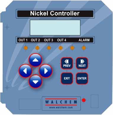
4.1 Front Panel
Backlit LCD Display
Output LEDs
Setting Adjustment Keys
Menu/Function Keys
USB LED
On/Off Power Switch
USB Connector
Figure 5 Front Panel
4.2 Display
A summary screen is displayed while the WNI controller is on. This display will show a bar graph of
the nickel concentration relative to the set point, the actual nickel concentration value, and current
operating conditions.
Towards the center of the bar graph is an (S), which represents the set point. For each 1% rise above the
set point a vertical line appears to the right of the (S). For each 1% drop below the set point a vertical
bar appears to the left of the (S). There are small breaks in the bars at each 5%. If high or low alarm
limits are reached, then either an (H) or (L) will appear.
If you have the pH option board installed, the bar graph of nickel concentration relative to set point is
not shown. In its place will be the pH reading as shown below.
The operating conditions which may be displayed on the bottom line of the display are: Control Delay
30* (number counts down), Sensor Error, Light Bulb Out, No Sample, Plate Out, Manual Output*
Interlock, Output Disabled*, Pump Overrun, High/Low Alarm, Turnover Limit, Calibration Time,
Outputs On* and Normal*
*These messages do not activate the diagnostic alarm relay.
141.98 Ni 6.01 5.20pH
Normal Normal
Figure 6 Summary Screen
4.3 Keypad
The keypad consists of 4 directional arrow keys and 4 function keys. The arrows are used to move the
adjustment cursor and change settings, while the function keys are used to enter values, and navigate the
various menu screens. The function keys are ENTER, EXIT, NEXT, and PREV (previous). NEXT and
PREV scroll through the various menu choices. ENTER is used to enter a submenu and to enter a
value. EXIT is used to back up one menu level. If you are at the main menu level, EXIT will return you
to the Summary Display.
To change a value in a submenu, the left/right arrow keys move the cursor left and right to each digit or
option that can be changed. The up/down arrows will change numeric values up or down, or scroll
through option choices. Press ENTER only when you have finished making all of the changes for that
menu screen.
4.4 Access Code
The WNI series controller is shipped with the access code disabled. If you wish to enable it, see Section
5.7 for operation. With the access code enabled, any user can view parameter settings, but not change
them. Note that this provides protection only against casual tampering. Use a lock on the cover latch if
you need more protection.
4.5 Startup
Initial Startup
After having mounted the enclosure and wired the unit, the controller is ready to be started.
Plug in the controller and turn on the power switch to supply power to the unit.
The display will show the WNI series model number then revert to the top level summary screen with
"Control Delay" for a status message. This message will be displayed for approximately 30 seconds. In
some situations, the user may not want the unit to be controlling and possibly turning on pumps when it
is first powered on. This allows you enough time to enter the Output menus and disable the outputs.
The only difference in the controller operation during these 30 seconds is that it will not activate any
outputs. All measurements are live and all menus are accessible. Scroll through the menus, calibrate the
sensor, and set the control parameters as detailed in Section 5, Operation.
If you turn the power to the controller OFF, at the next power-up all outputs will revert back to
automatic mode, where they will activate based upon the programmed set points.
Move to the “OUT 1” menu and change the set point, dead band and time limit to your desired values.
Refer to Section 5.5. If you want to keep track of the volume of nickel pumped, or track metal
turnovers, this is also set in the “OUT 1” menu in the “TOTAL 1” menu.
15If you have the pH input option, then the set points are found in the “pH (Output 3)” menu. Refer to
section 5.6.
Outputs 2 and 4 are intended for the addition of chemicals (such as hypophosphite or borohydride) in
proportion to the nickel addition, so the only set points found in these menus are related to totalizing the
chemical additions.
If you have the pH input option, move to the “pH Input” menu to calibrate the pH electrode. Refer to
Section 5.3.
Move to the “Sensor” menu to change the units of measure and perform a “New Sensor Setup” (2 point
calibration) of the nickel sensor. Refer to Section 5.2.
Alarm limits and setting the time are done in those respective menus.
If you have an optional 4-20 mA output card, you will see a menu for scaling the output signal to fit
your application. Refer to Section 5.9.
To return to the “Summary” screen, you may press EXIT until it is displayed, or you may wait 10
minutes and the display will revert to it automatically.
Normal Startup
Startup is a simple process once your set points are in memory. Simply check your supply of chemicals,
turn on the controller, calibrate it if necessary and it will start controlling.
4.6 Shut Down
To shut the WNI controller down, simply turn off the power. Programming remains in memory.
165.0 OPERATION
These units control continuously while power is applied. Programming is accomplished via the local
keypad and display.
To view the top level menu, press any key. The menu structure is grouped by inputs and outputs. Each
input has its own menu for calibration and unit selection as needed. Each output has its own setup menu
including set points, timer values, etc. as needed. After ten minutes of inactivity in the menu, the display
will return to the summary display. Keep in mind that even while browsing through menus, the unit is
still controlling.
5.1 Main Menu
The exact configuration of your WNI controller determines which menus are available as you scroll
through the settings. Certain menus are only available when you select certain options; which may be
hardware options (like the installation of a 4-20 mA output board) or software options (like choosing to
totalize on volume) or both. All settings are grouped under the following main menu items.
Sensor
pH Input Only if unit has pH option circuit board installed
pH Temperature Only if unit has pH option circuit board installed
Output 1
Output 2
Output 3 (pH)
Output 4
Alarm
Time
4-20mA 1 Only if 4-20mA option installed
4-20mA 2 Only if 2nd 4-20mA option installed
Access Code
Datalog Only if advanced USB feature is in model code
Config Only if advanced USB feature is in model code
Upgrade
The NEXT key travels forward through this list while the PREV key travels backwards through the list.
Pressing ENTER will Enter the lower level menu that is currently displayed.
17Possible Status Screens
* Control Delay 30
Sensor Error
pH Sensor Error
Temp Error Main Menu
Light Bulb Out
No Sample
Plate Out
* Manual Output
Interlock
* Output Disabled
Output Timeout
pH Output Timeout
High/Low Alarm
pH High/Low Alarm
Turnover Limit
1.98 Calibration Time
S
Normal * Outputs On
* pH Output On
* Normal
EXIT ENTER * These status screens DO NOT activate the diagnostic alarm relay
1 2
18
Nickel 1.98 g/L Nickel 1.98 g/L Nickel 1.98 g/L Nickel 1.98 g/L Nickel 1.98 g/L Nickel 1.98 g/L
Sensor pH Input 4.50 pH pH Temperature Out 1 11:40 Out 2 11:40 Out 3 11:40
Figure 7 Main Menu
PREV. NEXT
1 3 3
Nickel 1.98 g/L Nickel 1.98 g/L Nickel 1.98 g/L Nickel 1.98 g/L Nickel 1.98 g/L Nickel 1.98 g/L
pH Out 11:40 Out 4 11:40 Alarm 4-20mA_1 12.4mA 4-20mA_2 12.4mA Time Thur 11:40
Nickel 1.98 g/L Nickel 1.98 g/L Nickel 1.98 g/L Nickel 1.98 g/L
Access Code DIS Datalog Config Upgrade
Legend Operation
Press Enter key to enter menu or submenu.
1 pH Input & Output menus are only present if pH option board is installed. Press Exit key to exit menu.
2 Menu is only present if no pH option board is installed. After 10 minutes of inactivity the controller will
automatically return to the summary screen.
3 4-20mA menu is only present if 4-20mA option is installed.5.2 Sensor Menu
The sensor menu provides the following settings: Calibration history (informational only), 2 point
calibration, 1 point calibration, sensor type (range) selection, and other calibration menus. Each is
discussed in detail below. Refer to the Sensor Menu chart on the next page.
Note: If you are programming the unit for the first time, press the PREV key once, and set the "Sensor
Type" menu first to choose the range that matches the sensor you have connected. Then press ENTER.
Cal'd Displays the date of the last sensor calibration.
I Pt Calibration Press ENTER to perform a 1 point calibration of the nickel sensor. This calibration is best performed
at normal operating temperature.
Have solution flowing through the flow-through sensor. Take a sample of the solution and note the
concentration displayed by the WNI controller. Carefully perform the normal laboratory analysis of
the nickel concentration. Calculate the offset by subtracting the displayed value from the lab results. If
the lab analysis is significantly different, adjust the offset in the 1 point calibration menu, using the
arrow keys to change the value and the +/- sign. If the controller's display is higher than the lab
analysis, the offset should be negative.
The maximum offset for a one point calibration is 5 g/l(0.45 oz/gal) from the last new sensor setup
value. If you have an offset larger than this, then perform a new sensor setup.
New Sensor Setup Press ENTER to set up a new sensor. First you see a warning message: "WARNING Chg sensor cal?
N" This acts as a safety precaution for those who may only be "browsing" through the menus. If you
enter the New Sensor Setup menu, you may easily, inadvertently, change the calibration of the sensor.
If you continue with the following procedures, you must recalibrate the new sensor.
Water....xxxx.x
Place the immersible sensor in clean tap or DI water, or circulate through the flow through sensor.
When the number on the display is constant, press ENTER.
Sample....xxxx.x
Place the sensor in the bath at a known concentration or restart pumping the bath sample through the
flow through sensor. No work should be going through the bath so that the concentration remains
constant. Ideally the bath should be at the typical operating nickel concentration. When the number on
the display is constant, press ENTER.
Smpl Conc
Use the arrow keys to change the displayed number to the actual concentration of the bath in
grams/liter or ounces/gallon, depending on the unit of measure you have selected, then press ENTER.
Days Btwn Cal Use the arrow keys to set the number of days that you would like to go by before recalibrating the sensor.
The controller will prompt you to recalibrate when that time has expired. Setting the number of days to
zero will disable this feature.
mV in Display This menu displays the mV from the sensor. It is useful for troubleshooting. The top line shows 2 live
voltage readings from the sensor in millivolts. The bottom line shows the stored values for each sensor
signal from the most recent new sensor set up calibration - specifically the signal values measured with
water.
Self Test This feature is a diagnostic tool that can help isolate a problem between the sensor and controller. Before
initiating the self test, the sensor MUST be disconnected from the controller in order to function properly.
When ENTER is pressed the controller disables the sensor inputs and injects 2 test signals, simulating a
properly functioning sensor. The controller will display "PASS" or "FAIL" along with a live mV reading.
If "PASS" is displayed then it indicates the controller is functioning properly and the problem is likely to
be with the sensor. See the troubleshooting section for further details. If "FAIL" is indicated, the controller
is defective. Consult your factory representative for service options.
19Nickel 1.98 g/L
Sensor
Sensor Menu
EXIT ENTER
PREV. NEXT
Sensor 1.98 g/L Sensor 1.98 g/L Sensor 1.98 g/L Sensor 1.98 g/L Sensor 1.98 g/L Sensor 1.98 g/L Sensor 1.98 g/L
Cal'd Mar/10/96 1 Pt Calibration New Sensor Setup Days Btwn Cal 7 Conc. Units g/L mV in Display Self Test
EXIT ENTER EXIT ENTER EXIT ENTER EXIT ENTER
EXIT ENTER
Adjust Offset
20
g/L + 0.10 . . . . WARNING . . . . Conc. Units g/L m 300.4 r 232.1 Self Test PASS
Chg Sensor Cal? N grams per Liter *H 20 m 811.1 r234.6 m 611 r 202
New Sensor Setup Conc. Units g/L
Water. . . 1230.8 ounces per Gal.
New Sensor Setup
Figure 8 Sensor Menu
Sample. . . 30.2
New Sensor Setup . . . . WARNING . . . .
Smpl Conc 5.04 Check Set Points
Operation
Press Enter key to enter menu.
Press Exit key to exit menu.
Blinking fields may be edited with the adjust arrows.
Press Enter when modification is complete to return
to Main Menu Level.5.3 pH Input Menu
(Only appears if pH option board is installed – in WNI411 models)
The pH input menu provides the following: 1-Point Calibration, 2-Point Calibration, pH millivolts and
Self Test. Each is discussed in detail below. Refer to the pH Input Menu chart.
Cal'd Displays the date of the last electrode calibration.
2 Pt Calibration If using manual temperature compensation, the first display will be:
Cal Temp °F/C 68
Use the arrow keys to enter the actual temperature of the buffer solutions. If using automatic
temperature compensation, this display will not appear. Press ENTER to continue.
Rinse Electrode
Remove the electrode from the process and rinse it off. Press ENTER to go to the next step.
First Buffer
This is a prompt to place the electrode in the first buffer. In a few seconds the controller will
automatically go to the next step.
1st Buffer 7.00
The bottom line will display "1st Buffer" on the left hand side and "7.00" on the right hand side.
Use the arrow keys to set the pH value of the 1st buffer, then press ENTER. The top line will now
show the temperature and the mV input from the electrode. The mV will blink until the value is
stable. The controller will automatically go onto the next step or you may press ENTER to go to
the next step.
Rinse Electrode
Remove the electrode from the buffer and rinse it off. Press ENTER to go to the next step.
Second Buffer
This is a prompt to place the electrode in the second buffer. Again, in a few seconds the controller
will automatically go to the next step.
2nd Buffer 4.00
The bottom line will display "2nd Buffer" on the left hand side and "4.00" on the right hand side.
Use the arrow keys to set the pH value of the 2nd buffer, then press ENTER. The top line will now
show the temperature and the mV input from the electrode. The mV will blink until the value is
stable. The controller will automatically go onto the next step or you may press ENTER to go to
the next step.
The controller will go on to the next step once the mV signal is stable.
Cal Successful/Cal Failed
If the electrode response is good, then the display will read "Cal Successful". If the mV output of
the electrode did not change enough between the two buffer solutions, it will read "Cal Failed". A
failure usually means that the electrode needs to be cleaned, or replaced. It will also display the %
difference from theoretical slope. A failure occurs if the slope is more than 80% different than
theoretical.
Continue Y
The controller will hold this display until you replace the electrode in the process and press
ENTER. Control will not begin until ENTER is pressed or 10 minutes go by.
1 Pt Calibration This calibration procedure assumes that the sensor is installed in the sample loop and a one point
process calibration will be done to match the reading of a laboratory meter. Press ENTER to begin
the calibration.
Adjust Offset
Adjust the desired offset value using the left/right and up/down arrow keys and pressing ENTER.
Be sure to change the plus/minus sign for adjustment in the appropriate direction.
For example, if an independent laboratory measurement has indicated that the pH displayed by the
WNI controller is 0.1 pH units low, a plus 0.1 pH unit offset would be entered.
The maximum adjustment range is ±0.99 pH units. If more adjustment is needed, it is a sign that
the electrode has aged and a two point calibration should be performed. If the electrode fails the 2
point calibration, it should be replaced.
Remember, a two point calibration will always be more accurate than a one point calibration.
21Days Btwn Cal Use the arrow keys to set the number of days that you would like to go by before recalibrating the
electrode. The controller will prompt you to recalibrate when that time has expired. Setting the
number of days to zero will disable this feature.
Sensor mV This menu displays the mV from the electrode. It is useful for troubleshooting.
Self Test Press ENTER to perform a self-test. If it says "FAIL" in the upper right hand corner, this indicates
a problem with the controller which should be returned for repair. If it passes, and you have a
problem calibrating, it is an electrode or preamp problem.
pH Input Menu
This menu is only available in the WNi411 model.
Nickel 1.98 g/L
pH Input
EXIT ENTER
PREV. NEXT
pH Input 10.00pH pH Input 10.00pH pH Input 10.00pH pH Input 10.00pH pH Input 10.00pH pH Input 10.00pH
Cal'd Mar/10/96 2 Pt Calibration 1 Pt Calibration Days Btwn Cal 7 Sensor mV -177.0mV Self Test
EXIT ENTER
Self Test Pass
2 Pt Calibration Adjust Offset S1130 mV T1368mV
Cal Temp °F 68 pH +.10
2 Pt Calibration
Rinse Electrode
2 Pt Calibration
First Buffer 10.00
Use arrow keys
76°F -163.4mV to adjust values, then
1st Buffer 10.00 press ENTER to set
2 Pt Calibration
Rinse Electrode
2 Pt Calibration
Second Buffer
76°F 179.4 mV
2nd Buffer 4.00
Operation
2 Pt Calibration Press Enter key to enter menu.
% Difference -1.3% Press Exit key to exit menu.
2 Pt Calibration Blinking fields may be edited with the adjust arrows.
Continue Y Press Enter when modification is complete to return
to Main Menu Level.
Figure 9 pH Input Menu
225.4 Temperature Menu
(Only appears if pH option board is installed – in WNI411 models)
The temperature menu contains the following settings: Calibrate and Units (if the Pt100 or Pt1000
sensor is detected when the unit is powered on) or Manual Temp and Units (if no Pt100 or Pt1000
sensor is detected at power-up). Refer to the Temperature Menu chart below.
Calibrate To Calibrate the Temperature, use a thermometer to measure the fluid temperature and adjust the WPH
controller to match. Once Calibrate is entered, the unit continuously displays temperature readings.
Press the Up or Down arrow key to change the value displayed to match the thermometer. You must
press ENTER to activate the new calibration. You must press the EXIT key to exit calibration.
Man Temp This menu appears only if no temperature element is connected at power-up. Use the arrow keys to
adjust the temperature displayed to match that of the water.
Units You may choose to display temperature in °C or °F. Press ENTER and the Up or Down Arrow keys to
change the temperature units for display.
Possible Status Screen
Nickel 1.98g/L Temperature Err
Temperature Menu
Temperature
EXIT ENTER
PREV. NEXT
1
Temp 68°F Temp 68°F Temp
Calibrate Man Temp 68 Units °F
EXIT ENTER EXIT ENTER
Calibrate Units °F
Temp °F 68 °F
Calibrate Units °C
Temp °C 20.1 2 °C 2
Legend
1 Menu wording that appears when Manual Temperature Compensation is selected.
2 Menu wording that appears when °C units are selected.
Figure 10 Temperature Menu
235.5 Output 1 Menu
The Output 1 menu is for nickel control and provides the following independent settings: Set Point,
Dead Band, Time Limit, Interlock, Total, Output Mode, HOA. The Control menu will be indicated on
the display by one of the following:
Out 1 A OFF Indicates that the output is currently OFF.
Out 1 A 10:00 Indicates the length of time that the output has been ON.
Out 1 A Intrlck Indicates that control has been suspended because the Interlock switch is Open
Out 1 A TIMEOUT Indicates that the output has been on longer than the Time Limit.
(The 'A' indicates that the output is being controlled automatically. An “O” indicates the output is in Off
mode. An “H” indicates the relay is in Hand mode.)
Set Point Use the arrow keys to adjust the display to read the desired set point value of the bath. Press ENTER to accept
the change.
Dead Band Use the arrow keys to set the desired dead band, then press ENTER. For Microetch Mode, for example, If the
set point is 50.00 g/l, and the dead band is 0.5 g/l, then the relay will close at 50 g/l and open 0.5 g/l away from
50 (49.5 g/l).
HIGH SET
POINT Pump On Pump On
Pump Off
DEAD
BAND
Ni
TIME
ZERO DEADBAND: NOT RECOMMENDED
HIGH SET
POINT
Pump On & Off rapidly, damaging relay
Ni
TIME
24Time Limit Use the arrow keys to set the time limit (min:sec) for the output to be active, then press ENTER. If it is set for
"0:00", no limit will be imposed, and the output could stay on forever.
Reset Timer This menu only appears if the output mode has been selected as a Low Set Point, or a High Set Point and the time
limit has expired.
Determine the reason that the output stayed on too long, and once the problem has been solved, press ENTER to
reset the timer.
Interlock Use the Up and Down arrows to toggle between Y(Yes) and N(No). Choosing Y means that the output will
deactivate if the device attached to the controller is open. For example, if the sensor is installed in a recirculating
pipe line, a flow switch that is closed if flow is sufficient and open if flow is insufficient may be installed in the
line, so that if flow past the sensor stops, the controller will not pump in chemicals based on a stagnant sample.
Similarly, a level switch may be attached to prevent control of an empty batch tank.
Total 1 Press ENTER to program the timer/totalizer functions. The totalzer function allows you to track how much time
the output has been on (Total as Time), the volume of chemical that has been added (Total as Vol) or notify you
when the bath is ready to be replaced based on the number of metal turnovers (Total as Turns).
Total as Vol calculates the volume added by multiplying the relay on-time by the pump flow rate programmed.
Total as Turns calculates metal turnovers by multiplying the relay on-time by the pump flow rate, divided by the
volume equal to one metal turnover. An alarm is activated when the number of metal turnovers reaches the
programmed turnover limit.
Reset Total
Use the arrow keys to toggle between Y(Yes) and N(No) to reset the totalizer.
Total As
Press ENTER, then use the Up and Down arrows to choose whether to totalize in units of time, volume or nickel
metal turnovers.
Turnover Limit
Only appears if you choose to totalize by metal turnovers. Use the arrow keys to enter the maximum number of
turnovers. The controller will prompt you when this number has been exceeded.
Turnover Volume
Only appears if you choose to totalize by metal turnovers. Enter the number of gallons (G) or liters (L) that equals
one metal turnover. The unit of measure displayed correlates with that of the rate units selected in the next menu.
Rate Units
Only appears if you choose to totalize by volume or metal turnovers. Press ENTER, then use the arrow keys to
toggle between Gallons per Hour, mL per minute or Liters per hour. These units of measure will be used to enter
the rate at which the replenishment pump adds chemicals.
Pump Rate
Only appears if you choose to totalize by volume or metal turnovers. Use the arrow keys to set the flow rate of
the replenishment pump.
HOA Use the Left and Right arrows to move between Hand, Off and Auto. In Hand (Manual) mode, the output will be
turned on immediately for a maximum of 10 minutes. In the Off mode, the output will be turned off indefinitely.
In the Auto mode, the output turns on and off in response to changes in the process value relative to the set point.
The letter inside the block on the status screen indicates which mode the output is in. If power to the controller is
lost, it will revert back to Auto mode when power is restored.
25Possible Status Screens
Out 1
Out 1 A
A Off
Intrlck
Output 1 Menu
Nickel 1.98 g/L Out 1 A Timeout
Out 1 A 11:40 * Out 1 H 9:59
* (If placed in Hand mode, a timer indicates
how much time is left before turning off
EXIT ENTER
automatically.)
1
Out 1 A 11:40 Out 1 A 11:40 Out 1 A 11:40 Out 1 A Overrun
Set Point 2.10 Dead Band 0.10 Time Limit 0:00 Rest Timer N
PREV. NEXT
Out 1 A 11:40 Out 1 A 11:40 Out 1 A 11:40
Total 1 0.5 Gal Interlock N HAND OFF >AUTO
EXIT ENTER
2 2 3 3
Total 1 0.5Gal Total 1 0.5Gal Total 1 0.5Gal Total 1 0.5Gal Total 1 0.0TURN Total 1 0.0TURN
Reset Total Y Total As Vol Rate Units G/h Pump Rate 1.00 Turnover Lim 5 Turn Vol (G) 200
EXIT ENTER
EXIT ENTER EXIT ENTER
Total 1
Reset All?
0.5Gal
Y
Operation
Total As Vol Rate Units G/h Press Enter key to enter menu.
Total As Time Gal per hour
Press Exit key to exit menu.
Total As Volume L per hour Blinking fields may be edited with the adjust arrows.
Press Enter when modification is complete to return
Total As Turns mL per min
to Main Menu Level.
Legend
1 Menu appears if a limit timer has expired.
2 Menu appears when Total As Volume or Total As Turns
is selected
3 Menu appears when Total As Turns is selected
Figure 11 Output 1 Menu
265.6 Output 2 and 3 Menus
The Out 2 and 3 menus are separate from each other but operate in exactly the same way. Each menu
provides the Total and H O A settings. These additional outputs are activated simultaneously with
Output 1 and are provided to be able to add other bath components in proportion to the nickel, and
display independent replenishment totals.
If a pH option board is installed, Output 3 will be replaced by a pH Output menu.
Out 2 A OFF Indicates that the output is currently OFF.
Out 2 A 10:00 Indicates the length of time that the output has been ON.
Out 2 A Intrlck Indicates that control has been suspended because the Interlock switch is Open
Out 2 A TIMEOUT Indicates that the output has been on longer than the Time Limit.
(The 'A' indicates that the output is being controlled automatically. An “O” indicates the output is in Off
mode. An “H” indicates the relay is in Hand mode.)
Total 2 or 3 Press ENTER to program the timer/totalizer functions. The totalzer function allows you to track how much
time the output has been on (Total as Time), or the volume of chemical that has been added (Total as Vol).
Total as Vol calculates the volume added by multiplying the relay on-time by the pump flow rate programmed.
Reset Total
Use the arrow keys to toggle between Y(Yes) and N(No) to reset the totalizer.
Total As
Press ENTER, then use the Up and Down arrows to choose whether to totalize in units of time or volume.
Rate Units
Only appears if you choose to totalize by volume. Press ENTER, then use the arrow keys to toggle between
Gallons per Hour, mL per minute or Liters per hour. These units of measure will be used to enter the rate at
which the replenishment pump adds chemicals.
Pump Rate
Only appears if you choose to totalize by volume. Use the arrow keys to set the flow rate of the replenishment
pump.
HOA Use the Left and Right arrows to move between Hand, Off and Auto. In Hand (Manual) mode, the output will
be turned on immediately for a maximum of 10 minutes. In the Off mode, the output will be turned off
indefinitely. In the Auto mode, the output turns on and off in response to changes in the process value relative to
the set point. The letter inside the block on the status screen indicates which mode the output is in.
If power to the controller is lost, it will revert back to Auto mode when power is restored.
27Possible Status Screens
Out 2 A Off
Out 2 A
Out 2 A
Intrlck
Timeout
Output 2 & 3 Menu
* Out 2 H 9:59
Nickel 1.98 g/L * (If placed in Hand mode, a timer indicates
Out 2 A 11:40 how much time is left before turning off
automatically.)
EXIT ENTER
PREV. NEXT
Operation
Press Enter key to enter menu.
Out 2 A 11:40 Out 2 A 11:40
Total 2 0.5 Gal HAND OFF >AUTO Press Exit key to exit menu.
Blinking fields may be edited with the adjust arrows.
Press Enter when modification is complete to return
EXIT ENTER to Main Menu Level.
Total 2 0.5Gal Total 2 0.5Gal Total 2 0.5Gal Total 2 0.5Gal
Reset Total Y Total As Vol Rate Units G/h Pump Rate 1.00
EXIT ENTER EXIT ENTER
Total As Vol Rate Units G/h
Total As Time Gal per hour
Total As Volume L per hour
mL per min
Figure 12 Output 2 and 3 Menu
285.7 pH Output (Output 3) Menu
(Only appears if the pH option circuit board is installed – in WNI411 models)
This menu is used to set the pH output set points. This menu provides the following settings: Set Point,
Dead Band, Time Limit, Mode, Interlock, Total and HOA.
pH Out A OFF Indicates that the output is currently OFF.
pH Out A 10:00 Indicates the length of time that the output has been ON.
pH Out A Intrlck Indicates that control has been suspended because the Interlock switch is Open
pH Out A TIMEOUT Indicates that the output has been on longer than the Time Limit.
Low Set Point Only appears if the Mode is Low Set Point or Time Prop Lo
Press ENTER if you want the Control relay to close if the process goes below a certain value. The status screen
message will be Output ON. This denotes a normal correction of the process value. If you want the status
message to be Low Alarm, indicating a problem, choose an Output Mode of Low Alarm as described below.
High Set Point Only appears if the Mode is High Set Point or Time Prop Hi
Press ENTER if you want the Control relay to close if the process above a certain value. The status screen
message will be Output ON. This denotes a normal correction of the process value. If you want the status
message to be High Alarm, indicating a problem, choose an Output Mode of High Alarm as described below.
Dead Band Use the arrow keys to set the desired dead band, then press ENTER. If the set point is pH 7.00, and the dead
band is 0.05 pH units, then the relay will close at pH 7.00 and open 0.05 pH units away from 7.00.
HIGH SET
POINT Pump On Pump On
Pump Off
DEAD
BAND
mV
TIME
ZERO DEADBAND: NOT RECOMMENDED
HIGH SET
POINT
Pump On & Off rapidly, damaging relay
mV
TIME
Time Limit This menu only appears if the output mode has been selected as a Low Set Point, or a High Set Point.
Use the arrow keys to set the time limit (min:sec) for the output to be active, then press ENTER. If it is set for
"0:00", no limit will be imposed, and the output could stay on forever.
29Reset Timer This menu only appears if the output mode has been selected as a Low Set Point, or a High Set Point and the
time limit has expired.
Determine the reason that the output stayed on too long, and once the problem has been solved, press ENTER
to reset the timer.
Mode Press the ENTER key to change the mode in which the output will operate. The relays may be a low set point or
a high set point. Use the arrow keys to scroll through the choices.
Low Set Point
Press ENTER when this is displayed to select a low set point. The relay will close when the process value goes
below the set point value. The summary screen will display that the output is on. A time limit menu will be
available, to prevent runaway control. An Interlock menu will be available to allow you to stop control.
High Set Point
Press ENTER when this is displayed to select a high set point. The relay will close when the process value goes
above the set point value. The summary screen will display that the output is on. A time limit menu will be
available, to prevent runaway control. An Interlock menu will be available to allow you to stop control.
Interlock Use the Up and Down arrows to toggle between Y(Yes) and N(No). Choosing Y means that the output will
deactivate if the device attached to the controller is open. For example, if the electrode is installed in a
recirculating pipe line, a flow switch that is closed if flow is sufficient and open if flow is insufficient may be
installed in the line, so that if flow past the electrode stops, the controller will not pump in chemicals based on a
stagnant sample. Similarly, a level switch may be attached to prevent control of an empty batch tank.
Total 3 Press ENTER to program the timer/totalizer functions. The totalzer function allows you to track how much
time the output has been on (Total as Time), or the volume of chemical that has been added (Total as Vol).
Total as Vol calculates the volume added by multiplying the relay on-time by the pump flow rate programmed.
Reset Total
Use the arrow keys to toggle between Y(Yes) and N(No) to reset the totalizer.
Total As
Press ENTER, then use the Up and Down arrows to choose whether to totalize in units of time or volume.
Rate Units
Only appears if you choose to totalize by volume. Press ENTER, then use the arrow keys to toggle between
Gallons per Hour, mL per minute or Liters per hour. These units of measure will be used to enter the rate at
which the replenishment pump adds chemicals.
Pump Rate
Only appears if you choose to totalize by volume. Use the arrow keys to set the flow rate of the replenishment
pump.
HOA Use the Left and Right arrows to move between Hand, Off and Auto. In Hand (Manual) mode, the output will
be turned on immediately for a maximum of 10 minutes. In the Off mode, the output will be turned off
indefinitely. In the Auto mode, the output turns on and off in response to changes in the process value relative to
the set point. The letter inside the block on the status screen indicates which mode the output is in.
If power to the controller is lost, it will revert back to Auto mode when power is restored.
30You can also read