Antares Warewash Dispensing System - Reference Manual Antares Series
←
→
Page content transcription
If your browser does not render page correctly, please read the page content below
Antares Warewash Dispensing System
Reference Manual Antares Series Online and downloadable
Product Manuals and Quick Start
Guides are available at
www.HydroSystemsCo.com
Please check online for the latest
version of this Reference Manual.
!
WARNING:
The Antares dispensing system
is intended to be installed by
experienced installers, in
accordance with all applicable
electrical and plumbing codes.
All dish machine and dispenser
power must be disconnected
during installation and/or
any time the dispenser cabinet is
opened.
NOTE: Always use proper lockout
tagout procedures when servicing
the dispenser.
Preface
This manual has been written and illustrated to present the basic installation,
operation, and servicing instructions of the Antares Warewash Dispensing
System. Guidelines will be suggested in reference to the preferred method
of installation, however, the variety of equipment and the surrounding
environment will dictate the actual installation of the Antares.
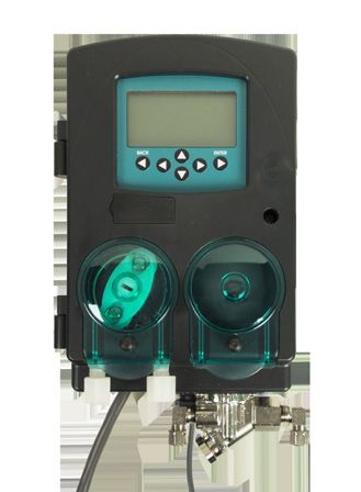
Antares DM-6000
P/N 10096880 REV A © Hydro Systems Company, Inc. 2014 HydroSystemsCo.com Toll Free: 1.800.543.7184 1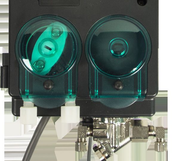
Table of Contents
 1 Product Benefits..................................................................................................................................... 4
 2 System Specifications........................................................................................................................... 4
 3 Mechanical Installation
			Overview........................................................................................................................................... 5
			Wall Mounting................................................................................................................................... 6
			Probe Mounting................................................................................................................................ 6
			     Rinse Injection Fitting........................................................................................................................ 7
			     Detergent Bulkhead Fitting............................................................................................................... 7
       Probe Kit Wiring Guides.................................................................................................................... 8
       .Rinse and Detergent Supply and Discharge Tubes.......................................................................... 9
			     Solenoid Water Feed......................................................................................................................... 9
 4 Electrical Installation
			Overview......................................................................................................................................... 10
			Probe Wiring................................................................................................................................... 10
			Electrical Connections.................................................................................................................... 11
			     Main Power Wiring.......................................................................................................................... 11
			     Detergent Signal Wiring.................................................................................................................. 11
			     Rinse Signal Wiring......................................................................................................................... 12
 5 Operating Modes.................................................................................................................................. 12
			Overview......................................................................................................................................... 12
 6 Operating Modes: Probe Operation Mode
			Detergent Control............................................................................................................................ 12
			Rinse Control.................................................................................................................................. 12
			Conveyor Machines........................................................................................................................ 13
			Door Machines................................................................................................................................ 13
			Pulse Feed...................................................................................................................................... 13
 7 Operating Modes: Probeless Operation Mode
			Initial Charge................................................................................................................................... 14
			Detergent Dose............................................................................................................................... 14
			     Low Detergent Alarm Threshold..................................................................................................... 15
			Rinse Control.................................................................................................................................. 15
			Rack Counts................................................................................................................................... 15
			     Rinse Delay Time (Door Machines Only)......................................................................................... 15
			     Rinse Saver (Door Machines Only)................................................................................................. 15
			     Rinse Feed Option (Door Machines Only)....................................................................................... 15
			     Tank Change Interval...................................................................................................................... 15
 8 Programming Menus, Screens, and Setup
			     Start-up Splash Screen................................................................................................................... 16
			Language Selection........................................................................................................................ 16
			     Date and Time Set.......................................................................................................................... 16
			Home Screen.................................................................................................................................. 17
			     Keypad, Menus, and Symbols........................................................................................................ 17
			     Navigation to User/Program Menus............................................................................................... 18
			Power Saver.................................................................................................................................... 18
			User Menus..................................................................................................................................... 18
			     User Prime Pumps.......................................................................................................................... 18
			De-Lime Cycle................................................................................................................................ 19
			     Max Detergent Time........................................................................................................................ 19
			     Manual Initial Charge...................................................................................................................... 19
			Manager Reports............................................................................................................................ 20
			     Download Productivity Report........................................................................................................ 20
			Installer Password........................................................................................................................... 20
			Configuration Settings.................................................................................................................... 21
			Detergent Control............................................................................................................................ 21
			Machine Type.................................................................................................................................. 21
			Detergent Type................................................................................................................................ 21
			     Pulse Feed Settings........................................................................................................................ 21
			Alarm Options................................................................................................................................. 22
			     Set Units of Measure...................................................................................................................... 22
			     Auto Switch Mode.......................................................................................................................... 22
			     Conveyor Rack Time....................................................................................................................... 22
			Initial Charge................................................................................................................................... 22
			     Display Live Conductivity................................................................................................................ 23
			     Display Live Rinse Temperature...................................................................................................... 23
			     Third Product Run........................................................................................................................... 23
			User Prime...................................................................................................................................... 23
			     Program Settings (Probe Mode Only)............................................................................................. 24
			     Detergent Set Point......................................................................................................................... 24
			     Manually Add Product.................................................................................................................... 24
			     Enter Set Point................................................................................................................................ 24
			     Use Tank Reading........................................................................................................................... 24
			     Rinse Pump Speed (Probe Mode).................................................................................................. 25
			     Third Product Pump Speed (Probe Mode)...................................................................................... 25
			     Rinse Feed Option (Probe Mode)................................................................................................... 25
			     Rinse Delay Time (Door Machines Only)......................................................................................... 26
			     Program Settings (Probeless Mode Only)....................................................................................... 26

P/N 10096880 REV A        © Hydro Systems Company, Inc. 2014              HydroSystemsCo.com             Toll Free: 1.800.543.7184             2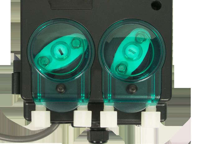
Table of Contents

 8  Programming Menus, Screens, and Setup (cont’d.)
			     Detergent Initial Charge.................................................................................................................. 26
			Detergent Dose............................................................................................................................... 27
			     Detergent Dose Interval.................................................................................................................. 27
			     Rinse Pump Speed (Probeless Mode)............................................................................................ 27
			     Third Product Pump Speed (Probeless Mode)............................................................................... 28
			     Rinse Feed Option (Probeless Mode)............................................................................................. 28
			     Rinse Delay Time (Door Machines Only)......................................................................................... 28
			     Low Detergent Alarm Threshold..................................................................................................... 28
			     Alarm Settings Menu....................................................................................................................... 29
			     Low Detergent Alarm Delay/Detergent Overfeed ........................................................................... 29
			Stop Alarm...................................................................................................................................... 29
			     Machine Clean Alarm Setting (Probed and Probeless)................................................................... 29
			     Conductivity Probe Range Setting (Probe Mode Only)................................................................... 30
			     Change Tank Alarm......................................................................................................................... 30
			     Change Squeeze Tube Time........................................................................................................... 30
			     Low Rinse Temp Setting................................................................................................................. 30
			Installer Service............................................................................................................................... 30
			Service Pumps................................................................................................................................ 31
			     View Pump Configuration............................................................................................................... 31
			Name Pumps.................................................................................................................................. 31
			Prime Pumps.................................................................................................................................. 31
			Pump Calibration............................................................................................................................ 32
			View Calibration.............................................................................................................................. 32
			     Calibrate Pumps (Non-Solenoid).................................................................................................... 32
			     Calibrate Pumps (Solenoid)............................................................................................................ 32
			     Enter Product Cost......................................................................................................................... 33
			     Tube Replacement Date.................................................................................................................. 33
			     Set Pump Type................................................................................................................................ 34
			     Set Pump Product.......................................................................................................................... 34
			     Set Pump Install.............................................................................................................................. 34
			     View Amount Pumped.................................................................................................................... 34
			     Clear Data Log................................................................................................................................ 35
			     Initial System Setup........................................................................................................................ 35
			     Edit Installer Password................................................................................................................... 35
			     Edit Manager Password.................................................................................................................. 35
			     Edit Account Name/Edit Machine Name/Edit................................................................................. 36
			Company Name.............................................................................................................................. 36
			     Set LCD Contrast............................................................................................................................ 36
			     Set Date & Time.............................................................................................................................. 36
			Clear Settings................................................................................................................................. 36
			     View Software ID............................................................................................................................. 37
			     View Serial Number......................................................................................................................... 37
			     Signal Display Enable..................................................................................................................... 37
			     External Solenoid Enable................................................................................................................ 37
			Electric Cost/KWH.......................................................................................................................... 37
			     Water Unit Cost............................................................................................................................... 37
			     Full KW Power Usage..................................................................................................................... 37
			     Idle KW Power Usage..................................................................................................................... 38
			Water Volume/Wash........................................................................................................................ 38
			Data Transfer................................................................................................................................... 38
			Write Reports.................................................................................................................................. 39
			Read Setup..................................................................................................................................... 39
			Write Setup..................................................................................................................................... 40
			Update Firmware............................................................................................................................ 40
 9  Alarm Messages
			     Detergent Overfeed Stop Alarm...................................................................................................... 41
			     Machine Clean Alarm...................................................................................................................... 41
			     Conductivity Probe Faulty Alarm.................................................................................................... 41
			     Squeeze Tube Change Alarm......................................................................................................... 41
			     Change Tank Alarm (Probeless Mode)............................................................................................ 41
			     Low Rinse Temperature Alarm........................................................................................................ 41
			     Pump Jam Alarm............................................................................................................................ 42
			     Probe Not Calibrated Alarm............................................................................................................ 42
 10 Reports
			Productivity Report......................................................................................................................... 43
			Settings Report............................................................................................................................... 44
			Activity Report................................................................................................................................ 46
			Diagnostic Report........................................................................................................................... 48
 11 Maintenance and Service
			     Spare Parts Listing ......................................................................................................................... 49
 12 Specifications and Warrant
			Specifications ................................................................................................................................ 51
 13 Index..................................................................................................................................................... 52

P/N 10096880 REV A         © Hydro Systems Company, Inc. 2014                HydroSystemsCo.com              Toll Free: 1.800.543.7184              3
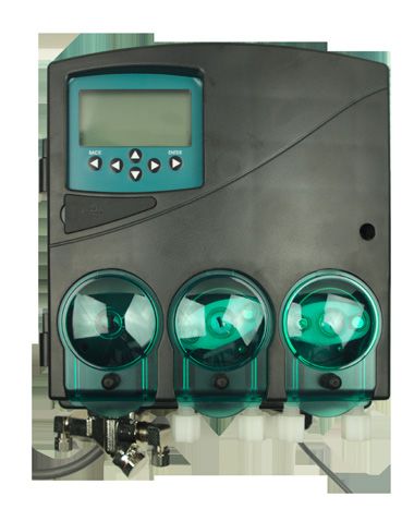
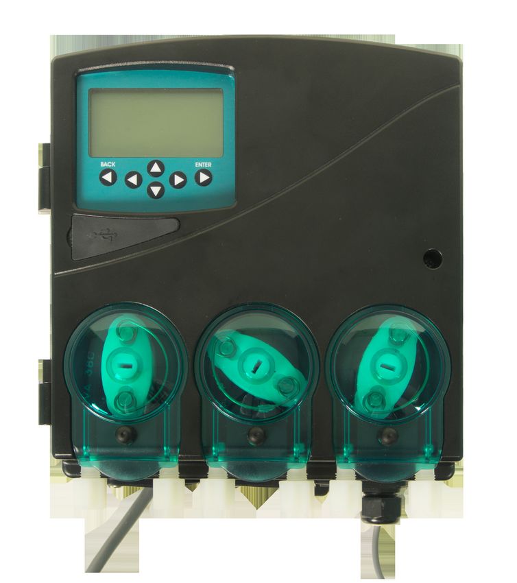
Product Benefits
Advanced Design
The Antares uses surface mount electronic components to provide powerful features in a small package.
A multi-line LCD screen allows intuitive programming of all options.

Reliability
The gasket-enclosed Antares Warewash Dispenser is highly water resistant and the electronics are protected
within the enclosure. The readout gives confirmation of detergent and rinse signals.

Versatility
The Antares can be configured as a conductivity probe controlled unit or as a probeless, time-based
dispenser. It can accept a 100-249VAC nominal (+/- 10% fluctuation) main power input at 50 or 60 Hz.
Rinse and Detergent control signals are universal “machine interface” types that are capable of accepting
any voltage from 24 to 240 VAC nominal (+/- 10% fluctuation) or 24 VDC (+/- 10% fluctuation). Antares can
control either capsule or liquid detergents.

Cost Savings
A special Rinse Saver Feature prevents rinse additive waste during fills of the washer. Digital electronics
ensure accurate detergent control and minimize overuse. The Antares contains energy management features
which can be used to track water and power usage and cost per rack over time. Reports indicate percentage
of racks washed successfully and racks where alarms occurred.

Intelligence
The Antares includes a rack counter as a “standard” feature. A unique “De-Lime” mode allows for
safe washer cleaning without detergent waste.

Choice of Options
A full range of programmable options are included, such as Rinse Delay, Variable Alarm Volume, and Manual
Prime for both rinse and detergent. Hardware options include detergent tank and rinse probe temperature.

Easy Service/Repair
The Antares features convenient front access for all services. No internal access to the cabinet is required for
installation and routine maintenance. Spare parts are available in modular form for fast, convenient repairs.

System Specifications
Detergent input signal                                    24 to 250VAC 50/60 HZ 20mA
Rinse input signal                                        24 to 250VAC 50/60 HZ 20mA
Tank fill input signal                                    24 to 250VAC 50/60 HZ 20mA

Motor/solenoid drive outputs for detergent and rinse
External solenoid output signal for rinse dissolver  24v DC Out

Conductivity probe for tank                               Included
Optional temperature probe for rinse and wash tank        Separate kit(s) required

Audible alarm within controller (single volume level) and external output for alarm (On/Off, no levels)
USB type A, used for USB drive storage and Flash programming LCD display, 8 line by 20 character with
adjustable contrast.

Multiple system configurations are available. Contact Hydro Systems customer service for more information.

P/N 10096880 REV A   © Hydro Systems Company, Inc. 2014     HydroSystemsCo.com       Toll Free: 1.800.543.7184   4
Mechanical Installation

Overview

This chapter describes the hardware installation of the Antares. In this chapter, you will:

•   Wall-mount the Antares
•   Mount and install the probe (if applicable)
•   Mount and install the rinse injection fitting
•   Mount and install the detergent bulkhead fitting
•   Probe kit wiring guides
•   Install rinse and detergent supply and discharge tubes
•   Install solenoid (if applicable)

P/N 10096880 REV A   © Hydro Systems Company, Inc. 2014    HydroSystemsCo.com      Toll Free: 1.800.543.7184   5

Mechanical Installation

Wall Mounting

1. Choose an installation location that is:
   • Close to the product containers.                                                !
   • At a reasonable height for easy maintenance access and does
   		 not interfere with opening of doors.                                        WARNING:
                                                                                  The Antares dispensing system
   • Away from any direct sources of steam, water spray, and high                 is intended to be installed by
   		 temperatures.                                                               experienced installers in
   • Close enough to the dish machine electrical control panel to                 accordance with all applicable
   		 allow dispenser wiring without use of an external junction box              electrical and plumbing codes.
   		 (not provided) wherever possible. Wire harness is 11.5 feet.
2. Using mounting bracket as a template, mark holes to drill into                 All dish machine and dispenser
   mounting surface. For sheet metal mounting with screws and nuts,               power must be disconnected
   drill 1/4” (6 mm) holes. For wall anchors, drill holes as appropriate          during installation and/or
   for anchors used.                                                              any time the dispenser cabinet is
                                                                                  opened.
3. Attach mounting bracket to mounting surface with hardware
   provided.                                                                      Mounting Bracket
4. Hang unit on bracket.

                                                                                  Back of Unit
Probe Mounting (Probe Operation and Out of Product Alarm in                       Hang unit from
Probeless Mode only)                                                              this lip on to
                                                                                  Mounting
The probe senses the detergent concentration. Correct probe                       Bracket
placement is critical for accurate detergent concentration control.
Always use the new probe provided with the dispenser.                             Figure 3-3 Mounting Bracket

1.   Choose a mounting location that will allow the probe to be
     completely immersed in the wash tank solution, in an area that has
     a good flow of solution.
2.   Check for a probe hole. Many dish machines will have knockouts             Rubber Gasket            Retaining Nut
                                                                                                                                Lock
                                                                                                                               Washer
     provided for probe installation and/or will have existing probes.
     Previously punched probe holes may be suitable, but always
     confirm that the probe will be immersed in the wash tank solution
     before installing
3.   If no suitable probe hole is present, drill a 3/8” hole in the center of
     the probe location. Use a Greenlee (or similar) 7/8” hole punch to                              Plastic Washer
                                                                                                                         Nut                Nut
                                                                                  Dish Machine
     cut the final hole.                                                            Tank Wall        Rubber Gasket
                                                                                                                                   Ring
                                                                                                                                 Terminal

4.   Remove the probe retaining nut.
                                                                                  Figure 3-4 Probe Mounting
5.   From inside the dish machine tank wall, insert probe (with rubber
     gasket) into hole.
6.   From outside the dish machine tank wall, install second rubber
     gasket, plastic washer and probe retaining nut. Tighten finger-tight
                                                                                     !
     only. Using a wrench, snug retaining nut without over tightening.            WARNING:
                                                                                  Do not over-tighten the retaining
                                                                                  nut!

P/N 10096880 REV A   © Hydro Systems Company, Inc. 2014      HydroSystemsCo.com          Toll Free: 1.800.543.7184                  6
Mechanical Installation
Rinse Injection Fitting
1. Choose a location to install the rinse injection fitting at least 6”
below the dish machine rinse plumbing vacuum breaker to conform Compression Fitting
to plumbing codes. The injection fitting threads into 1/8” NPT female (tube from pump)
threads. If the dish machine rinse plumbing is thin-wall pipe, use a
saddle clamp with a 1/8” NPT threaded hole. If an optional pressure
switch will be used, thread the injection fitting into one side of the
pressure switch water source fitting pipe tee.
2. Check for a tapped hole to accommodate the fitting. A suitable hole Threads into
must be at least 6” downstream from the solenoid valve and vacuum rinse plumbing
breaker. On continuous rack, flight, or conveyor machines, be sure
this location is downstream from any rinse by-pass water pipe. Figure 3-4 Rinse Injection Fitting
3. If no suitable hole exists, drill an 11/32” hole in the rinse plumbing
injection location.
4. Tap the hole with a 1/8” NPT tap.
5. Install the injection fitting. Use thread sealant to ensure a leak-free
assembly.
!
WARNING:
Follow the instructions provided
Detergent Bulkhead Fitting (Liquid Detergent Only) with your solid, powder, or slurry
feed system for solenoid equipped
Correct placement of the detergent bulkhead fitting is critical for units instead of using the following
accurate detergent concentration control (in probe mode only). section.
1. Choose a mounting location that ensures the detergent bulkhead
fitting is:
• Above the water line in the tank.
• Close to the probe location (when possible).
• Discharging detergent directly into the wash tank and not on top of
any shelf areas or other obstacles that could prevent detergent from
falling directly into the wash tank.
2. Previously punched holes may be suitable, but always confirm that
the fitting is correctly placed.
3. If no suitable hole is available, drill a 3/8” hole in the center of the
detergent inlet location. Use a Greenlee (or similar) 7/8” hole punch
to cut the final hole. Figure 3-5 Detergent Bulkhead
Fitting
4. Remove the detergent bulkhead fitting retaining nut.
5. From outside the machine, insert the detergent bulkhead fitting (with
rubber gasket) into hole.
6. From inside the machine, install the second rubber gasket, plastic
!
washer and plastic retaining nut. Tighten finger-tight, then snug WARNING:
using wrench. Do not over-tighten the retaining
nut! The installation instructions
for the detergent bulkhead
fitting are for liquid detergent
feed systems only. Follow the
instructions provided with your
solid, powder, or slurry feed
system for solenoid equipped
units.
P/N 10096880 REV A © Hydro Systems Company, Inc. 2014 HydroSystemsCo.com Toll Free: 1.800.543.7184 7Mechanical Installation Rinse Probe Kit Wiring Guide Disconnect all power to the unit before opening the front cover. Connect the other end of the cable to the 10096829 rinse probe assembly using the crimp-on spade connectors. Attach the two smaller connectors to the rinse probe wires, and the two larger connectors to the 2-conductor cable. (Polarity is not important). T/C Probe Kit Wiring Guide Figure 3-6 Rinse Probe Kit Connect the end of the cable to the 10096824 rinse probe assembly using the crimp-on spade connectors and ring terminals included in the kit. Attach the two smaller spade connectors to the white thermistor wires, and the two larger connectors to the green & white wires of the 4-conductor cable. (Polarity is not important). Crimp the ring terminals to the black & red wires of the 4-conductor cable and attach the ring terminals to the threaded studs of the 10096824 probe, using the nuts and lock washers provided. (Polarity is not important) Figure 3-7 T/C Probe Kit P/N 10096880 REV A © Hydro Systems Company, Inc. 2014 HydroSystemsCo.com Toll Free: 1.800.543.7184 8
Mechanical Installation

Rinse and Detergent Supply and Discharge Tubes
1. Route the pump supply tubes from supply containers to the inlet (left) sides of each pump. Slip the tube
   fully through the compression nut into fitting and tighten.
2. Route the pump discharge tubes to the outlet (right) sides of each pump. Slip the tube fully through
   compression nut into fitting and tighten.
3. Route other end of the rinse pump discharge tube to the rinse injection. Slip the tube fully through
   compression nut into the fitting and tighten.
4. Route the other end of the detergent pump discharge tube to the detergent bulkhead fitting. Slip tube
   fully through compression nut into fitting and tighten.

NOTE: Supply and discharge tubes are not included with the standard unit.

                                  from
                                  water source

                                   pump discharge tube connection
                                    pump supply tube connection
DM-6221                                to detergent feed bowl
DM-6220
Figure 3-8 Product Pickup and Discharge tubing Connections Connection

Solenoid Water Feed (Solenoid Equipped Units Only)
If you are using a solid, powder or slurry feed system, you will need a          !
water source for the dispenser solenoid valve. This water supply may be
hot or cold but, for safety reasons, should not come from the boosted        WARNING:
temperature rinse water line on high temperature dish machines.              If the water source is hot, use only
                                                                             copper tubing. DO NOT use poly
The dispenser solenoid valve fittings are 1/4” (6mm) compression.            tubing.
Typically, a saddle clamp is used for the solenoid valve water source. If
the plumbing is steel or brass, drill an 11/32” hole and tap for 1/8” NPT
threads.

1. Install petcock valve to water source plumbing. Connect 1/4” copper
   or plastic tube to the valve.
2. Route tube to dispenser solenoid valve. Slide tube into water inlet
   side compression fitting and tighten.
3. Connect another 1/4” tube to the outlet side of the dispenser
   solenoid valve and route to the water inlet connection for the feed
   system.
4. Confirm that all compression fittings are tight.
5. Be sure to turn on water source valve prior to adjusting dispenser
   settings.

P/N 10096880 REV A   © Hydro Systems Company, Inc. 2014     HydroSystemsCo.com       Toll Free: 1.800.543.7184   9
Electrical Installation
Overview
This chapter describes the electrical connections of the Antares. In this chapter, you will connect:
• Probe wiring
• Electrical connections
• Main power wiring
• Detergent signal wiring (probe and probeless modes)
• Rinse Signal Wiring
NOTE: All electrical connections (except the probe) must be in either the dish machine control circuit panel or
an external junction box. Power cable (Type Y) is not field replaceable.
The dispenser is pre-wired with a multi-conductor electrical cable that must be run through a conduit to the
location where hard-wired connections are made on the dish machine.
Use a 1/2” (13 mm) ID water tight conduit meeting all local and national codes. A threaded fitting is present
on the bottom of the dispenser where the power cable exits to connect a 1/2” conduit fitting.
The probe wire is also pre-wired and should be routed to the probe location and cut to length if a probe is
used.
NOTE: The AC Mains are disconnected from the dispenser when the ON/OFF is in the OFF position. This is a
Type 1.A application.
Probe Wiring
1. Route the probe wire to the probe location. If you need to extend the probe wire, use high quality
corrosion resistant (waterproof is best) butt splices with a good quality crimping tool.
2. Strip wire ends and crimp on the ring lugs provided.
3. Connect the ring lugs to the probe with nuts and star washers provided. Be sure that connections are tight
and secure.
4. For optional rinse temperature probe, connect Black and Red wires from probe to internal interface
terminals Sensor 2, channel 1.
5. Connect Black and Red wires from probe to internal interface terminals Sensor 1, channel 1.
6. For optional tank temperature probe, connect Green and White wires from probe to internal interface
terminals Sensor 1, channel 2.
Lock
Rubber Gasket Retaining Nut Washer
Nut Nut
Dish Machine Plastic Washer
Tank Wall Ring
Rubber Gasket Terminal
Figure 4-1 Probe Wiring Sequence
P/N 10096880 REV A © Hydro Systems Company, Inc. 2014 HydroSystemsCo.com Toll Free: 1.800.543.7184 10Electrical Installation
Electrical Connections
Table 4-1
Wire Colors Circuit Voltage Function Internal Connector
Blue 100-250 VAC 50/60 Hz Main AC Power
Brown 100-250 VAC 50/60 Hz Main AC Power
Green/Yellow --- Earth Ground
Yellow +24-VDC or 24-250 VAC, 50/60 Hz Detergent Signal Trigger 1+
Yellow/White 24 VDC Negative or 24-250 VAC, 50/60 Hz Detergent Signal Trigger 1-
Purple +24-VDC or 24-250 VAC, 50/60 Hz Rinse Signal Trigger 2+
Purple/White 24 VDC Negative or 24-250 VAC, 50/60 Hz Rinse Signal Trigger 2-
Main Power Wiring
Connect the blue wire to one side of the voltage source. Connect the
brown wire to the other line of the voltage source. Main Power
Brown Line
Detergent Signal Wiring
The detergent signal input is an optically isolated signal input, include in Blue
table internal terminal locations that draws no more than 20 mA. It is a Line
universal voltage input that accepts any voltage listed in Table 4-1.
Detergent Signal Wiring – Probe Mode
Typical wiring locations are dispenser detergent power supply (DPS1 & Figure 4-2 Main Power
DPS2) or the wash motor contacts in the dish machine control panel. This Connections
power source is on when the dishwasher is running the wash pump.
• Connect Yellow (+DC or AC) and Yellow/White (-DC or AC) colored
wires to detergent power supply.
(+)Yellow
Detergent Signal Wiring – Probeless Mode
On conveyor type dishwashers, the detergent signal must occur only once (-) White/Yellow
Line
per dish machine fill/drain occurrence–beginning when the dish machine
fills. Typical wiring locations are an “on light,” an on/off switch if present, Detergent Signal 24-240 VAC~50/60Hz
or an electrical tank heat circuit between the tank heater switch and the or 24 VDC
thermostat. Each time this power source comes on and stays on for 10
seconds, the dispenser will feed the detergent initial charge amount. Figure 4-3 Detergent Signal Wiring
Diagram—Probe or Probeless
On door-type dishwashers, connect this signal input to the dispenser Mode
detergent power supply or the wash motor contacts in the dish machine
control panel. This power source is on when the dishwasher is running the
wash pump.
To facilitate Automatic Initial Charge on alternate machines or machines
that do not provide a rinse signal during the fill, connect the detergent
signal wires to a power source that occurs only once per fill/drain
occurrence beginning when the dish machine fills. Typical wiring locations
are a main ON/OFF switch or an on light.
• Connect Yellow (+DC or AC) and Yellow/White (-DCor AC) colored
wires to initial charge power source.
P/N 10096880 REV A © Hydro Systems Company, Inc. 2014 HydroSystemsCo.com Toll Free: 1.800.543.7184 11Electrical Installation
Rinse Signal Wiring
The rinse signal input is an optically isolated signal input that draws no
more than 20 mA. It is a universal voltage input that accepts any voltage (+) Violet
Line
listed in Table 4-1. Typical wiring locations are dispenser rinse power
supply (RPS1 & RPS2) or the rinse solenoid valve circuit in the dish (-) White/Violet
machine control panel. This power source is live whenever the dishwasher Rinse Signal 24-240 VAC~50/60Hz
is rinsing. When no suitable rinse signal connection is available, an optional or 24 VDC
pressure switch may be used with a constant power source instead.
• Connect Purple (+DC or AC) and Purple/White (-DC or AC) colored Figure 4-4 Rinse Signal Wiring
wires to rinse power supply (or constant power for pressure switch Diagram
installations).
• Interface board Output Wiring (internal Solenoid + options) 24V DC
Red = +DC, Black = -DC NOTE: If an external optional device
• 6211 Output 1 - Int Solenoid, Output 2 - Ext Sol, Output 3 - Ext Alarm will be used, you must supply your
• 6220 Output 1 - unused, Output 2 - Ext Sol, Output 3 - Ext Alarm own wire.
• 6321 Output 1 - Int Solenoid, Output 2 - Ext Sol 1, Output 3 - Ext Alarm,
Output 4 - Ext Sol 2
• 6330 Output 1 - Ext Sol 1, Output 2 - Ext Sol 2, Output 3 - Ext Alarm,
Output 4 -unused
Operating Modes
Overview
The Antares allows detergent control using two different modes:
1. Probe Mode—This mode requires a conductivity probe be mounted in the wash tank to measure
detergent concentration. Detergent is dispensed automatically when measured concentration levels fall
below the programmed set point.
2. Probeless Mode—No probe is required. An initial charge of detergent is dispensed when the machine
is filled and upon a specified signal from the dishwasher. Detergent dose is dispensed for a fixed
programmed time each time.
Rinse control and Rack counts are handled differently for each mode as described below.
Operating Modes: Probe Operation Mode
Detergent Control
In Probe Operating Mode, the controller begins monitoring the conductivity probe to determine detergent
concentration.
The detergent feed is activated as soon as the concentration calculated from the conductivity signal has gone
below the programmed set point and there is a detergent signal present. When the set point is reached the
detergent feed is de-activated.
The detergent signal from the washer should remain on while the wash tank motor is on,
otherwise the detergent feed will not activate. The detergent signal is typically wired to a power source
that is on when wash pump is running.
Low Detergent Alarm
If the conductivity is below the set point and has not increased by 10% within a programmed number of
racks, a visible and audible alarm will be activated. The alarm will sound at the end of each rack until the
conductivity rises by 10%. If the conductivity has not increased by 10% for twice the preset number of racks,
an alarm will be activated and the detergent feed will stop. Operator intervention is required to restart the
detergent feed.
P/N 10096880 REV A © Hydro Systems Company, Inc. 2014 HydroSystemsCo.com Toll Free: 1.800.543.7184 12Operating Modes: Probe Operation Mode Rinse Control In Probe Operating Mode, rinse signal input controls the rinse output. When the rinse signal is present, the rinse pump will run at the programmed speed until the rinse signal goes off. This varies depending on the selected rinse feed option for door machines. Conveyor Machines Rack Counts For conveyor machines, conveyor time is defined as the time it takes to move one rack length. A programmed conveyor time setting is used to count the number of racks on a conveyor machine. A rack is counted when the rinse on time equals the programmed conveyor time. Tank Change Interval To signal an alarm when it is time to change the tank water, a tank change interval can be used in conjunction with number of racks run since the initial charge. (In Probe Mode, this will require a separate initial fill signal to determine the initial charge.) Rinse Pump Rinse Saver is not a feature of conveyor machines. Instead, the rinse pump will run continuously as long as the rinse signal is active. However, the rinse pump will only operate if a detergent signal has occurred within the previous 90 seconds. Door Machines Rack Counts For door machines, a rack count will be registered each time the rinse signal toggles from Off to On. Tank Change Interval To signal an alarm when it is time to change the tank water, a tank change interval can be used in conjunction with number of racks run since the initial fill. Rinse Delay Time A rinse delay of 0-19 seconds can be programmed for door machines. The rinse delay will occur at the beginning of each rinse signal input. Rinse Saver The pump will only be allowed to operate continuously for a maximum of 20 seconds. After 20 seconds, the rinse signal input must toggle Off and back On again. Please note, this will also cause the rack count to be incremented The Rinse Pump will only operate if a detergent signal has occurred within the previous 90 seconds. Rinse Feed Option There are two options for the Rinse Pump to activate. Option 1 (Rinse on Rinse) will run the Rinse Pump each time the Rinse Signal activates (for the duration of time the signal is present). Option 2 (Rinse on Det) will run the rinse pump for a fixed time of 12 seconds each time the Detergent Signal activates. Please note, the Detergent Signal must be toggled On/Off for the rinse pump to run again. With each toggle, the rack count will be incremented. Pulse Feed Pulse Feed is used only with capsule-type detergent in Probe Operating Mode. If the conductivity reading is within the set point by a user-specified percentage, the detergent feed will be cycled On and Off (pulsed) at a user-selected frequency. Otherwise, the detergent feed will be on continuously. This allows the controller to gradually reach the set point without overshooting. If it is turned on, the user must choose between one of seven different fixed options for frequency and percentage with the set point. (For example, if the reading is within 80% of the set point, the default option is 2 seconds on, 6 seconds off. P/N 10096880 REV A © Hydro Systems Company, Inc. 2014 HydroSystemsCo.com Toll Free: 1.800.543.7184 13
Operating Modes: Probeless Operation Mode
Initial Charge
Door Machines
Whenever the dispenser receives a rinse signal that was not preceded by a detergent signal within 90
seconds prior (as in an initial fill), an automatic initial charge occurs. The automatic initial charge consists of
disabling the rinse feed and feeding detergent for the preset amount of time programmed for detergent initial
charge. Normal rinse signal activations within 90 seconds after a detergent signal will not trigger an initial
charge.

A five minute lockout timer begins at the start of the initial charge to prevent additional triggering if multiple
rinse signals are detected during fill.

Alternate Door Machines
An Automatic Initial Charge in a Alternate Door machine occurs each time the dispenser receives a detergent
signal input (with 2 second qualification). The detergent feeds for the programmed time for initial charge.

Conveyor Machines
Each time the dispenser in a conveyor machine receives a detergent signal input (with 3 second qualification)
that remains on for 10 seconds continuously, an automatic initial charge occurs. The detergent feeds for the
programmed time for detergent initial charge.

The rinse pump is locked out during the detergent initial charge if the rinse signal was previously on. When
the initial charge is complete, the rinse pump will not turn back on until the rinse signal is toggled Off
to On.

Because the initial charge will occur each time a detergent signal occurs, the source of the detergent signal
must remain on for the duration of time the tank is full, or must not occur more than one time per machine
fill. If the detergent signal is toggled and qualified for 3 seconds, then continuously on for 10 seconds,
the dispenser will receive another signal. If this happens before the initial charge completes, it will run the
detergent for another initial charge cycle.

The initial charge will run the full charge time regardless if the detergent signal is turned off prior to
completion.

On a conveyor machine, the detergent signal is typically wired to an “on light” or an electrical tank heat on/off
switch. Each time the power source comes on, the dispenser feeds the detergent initial charge amount.

If Manual Initial Charge is selected, there is no automatic initial charge.

Detergent Dose
Door Machines
When the detergent signal on a door machine is activated with (3 second qualification) a detergent dose of a
programmed time will occur once per programmed detergent dose rack interval. The rinse signal must then
activate to run the rinse pump before detergent can run again.

Door Machines with No Rinse Signal on Fill (Alternate Door machines)
If a door machine has no rinse signal upon fill, select this option. In an Alternate Door Type dishwasher
Detergent is dispensed when the Rinse Signal is activated based on the detergent dose interval and detergent
dose time.

Conveyor Machines
On a conveyor machine, a detergent dose of a programmed time will occur when the accumulated Rinse On
signal time reaches the conveyor rack time multiplied by a programmed detergent dose interval (1, 2, or 3
racks). The rinse signal does not need to be toggled off and on for another dose to occur.

P/N 10096880 REV A   © Hydro Systems Company, Inc. 2014      HydroSystemsCo.com       Toll Free: 1.800.543.7184      14
Operating Modes: Probeless Operation Mode

Low Detergent Alarm Threshold
A low detergent alarm is available for Probeless Operating Mode if a conductivity probe is installed in the
same manner as for Probe Operating Mode. When the probe is connected, it senses detergent conductivity at
20 different preset threshold values (0-19). Each setting is equivalent to a calibrated conductivity value divided
by 10 (i.e., the default setting of 5 is equal to a conductivity setting of 50). If the conductivity goes below the
setting and remains there without rising at least 10% for a programmed number of racks, a visible and audible
alarm will be activated. The alarms will remain on until the conductivity rises above the threshold point. If the
conductivity has not increased for twice the preset number of racks, an Overfeed Alarm will be activated and
the detergent feed will stop. Operator intervention is required to restart detergent feed.

Rinse Control
In Probeless Operating Mode, rinse signal input controls the rinse output. When the rinse signal is present, the
rinse pump will run at the programmed speed until the rinse signal goes off. This varies depending on the
selected rinse feed option for door machines.

Rack Counts
Door Machines
For door machines, a rack count will be registered each time the rinse signal toggles from Off to On. Door
machines include a rinse feed option which, when set to Rinse on Det, increases the rack count when the
detergent signal toggles from Off to On.

Alternate Door Machines
a rack count will be registered each time the rinse signals toggles from Off to On.

Conveyor Machines
For conveyor machines, conveyor time is defined as the time it takes to move one rack length. A programmed
conveyor time setting is used to count the number of racks on a conveyor machine. A rack is counted when
the rinse on time equals the programmed conveyor time.

Rinse Delay Time (Door Machines Only)
A rinse delay of 0-19 seconds can be programmed for door machines. The rinse delay will occur at the
beginning of each rinse signal input.

Rinse Saver (Door Machines Only)
The pump will only be allowed to operate continuously for a maximum of 20 seconds. After 20 seconds, the
rinse signal input must toggle Off and back On again. Please note, this will also cause the rack count to be
incremented

The Rinse Pump will only operate if a detergent signal has occurred within the previous 90 seconds.

Rinse Feed Option (Door Machines Only)
There are two options for when the Rinse Pump will activate. Option 1 (Rinse on Rinse) will run the Rinse
Pump each time the Rinse Signal activates (for the duration of time the signal is present). Option 2 (Rinse on
Rinse) will run the rinse pump for a fixed time of 12 seconds each time the Detergent Signal activates. Please
note, the Detergent Signal must be toggled On/Off for the rinse pump to run again. With each toggle, the rack
count will be incremented.

Tank Change Interval
To signal an alarm when it is time to change the tank water, a preset tank change interval can be used in
conjunction with accumulated racks since the initial fill.

P/N 10096880 REV A   © Hydro Systems Company, Inc. 2014    HydroSystemsCo.com      Toll Free: 1.800.543.7184    15
Programming Menus, Screens, and Setup
Start-up Splash Screen
At start-up, the controller displays a splash animation consisting of a short series of bitmap images that
identify the manufacturer and device. Upon the initial start-up, this screen defaults to allow selection for
language of operation. Additional language choices can be selected if a USB Language Key is available and
selectable from the menu at power up.

Pressing any key during boot-up skips the splash screen and takes the user to the date and time input
screen.

Language Selection
The language selection screen follows the splash screen at the first                     LANGUAGE
power-up or when a USB drive is in place at power-up. After that, the             ENGLISH
                                                                                  SPANISH
splash screen leads to the Date and Time Set screen.

The language selection screen provides a selectable menu for the
languages that are available on the device (or on a language key if one
is installed prior to power-up). The screens will always include English        Default No USB Key Installed
and one additional language as default selections. In North America, the
additional default language option is Spanish. In Europe, it is German.
Language files have an .LNG extension. Additional languages may be                       LANGUAGE
                                                                                  ENGLISH
downloaded from a USB Language Key.                                               SPANISH
                                                                                  FRANCAIS
                                                                                  DEUTSCH
To load, power must be turned off. Connect the Language Key and                   SVENSKA
start up. Select a language from the list and load onto the controller.           PORTUGUESE
Once a language has been selected, it replaces the second default
language choice and becomes the selected language for this controller.          With USB Key Installed
English will always remain one of the available default languages. The
USB Language Key can be removed as soon as the Date and Time Set
screen appears.                                                                         DATE & TIME
                                                                                    ▼
                                                                                 < 2013-02-15 >
                                                                                    ▼

Date and Time Set                                                                  YYY-MM-DD         HH:MM
The start-up continues with the Date and Time Set screen. The date
follows the ISO 8601 standard format with four digits for the year              Date and Time
followed by two digits for the month and two digits for the day. (e.g.
2013/02/15). The time also follows an ISO 8601 standard, but is limited                     ERROR
to hours and minutes on a 24-hour clock (for example, instead of
8:00pm, you would enter 20:00).                                                             INVALID
                                                                                           DATE/TIME
If a date is entered that is not valid, an error message will appear. Select
Enter or Back to return to the Date and Time Set screen.
                                                                                Error

P/N 10096880 REV A   © Hydro Systems Company, Inc. 2014    HydroSystemsCo.com           Toll Free: 1.800.543.7184   16
Programming Menus, Screens, and Setup
Home Screen
The home screen displays information during periods of activity,
including company name, rack count, operating mode, tank NOVA CONTROLS
conductivity and temperature, rinse temperature, pump activity, and Racks: 00000 PROBE
signal activity. Two distinct options for additional features can be Cond: 000 WTemp:000
accessed by the press of a button. Setpt: 000 RTemp:000
Signl: 1 0
Pump: DET RIN SAN
The display is in ready state when a pump is enabled in the Alarm: ** LOWDET **
configuration and the pump name is shown. The display is in active
state when a pump is running and the pump name is inversely
displayed. Pump names show the first three characters of the pump’s
name. (Keep this in mind when naming pumps.) If a pump is not
enabled, the three character pump name will be blank.
If enabled in the installer setup menu, signal states are displayed as
either 0 or 1.
Most recent alarms will be displayed in the alarm status line, when
there is an active alarm. If there is no active alarm, this area is blank.
(See the section on Alarms for a list of all possible alarms.)
The rack count is displayed in five digits.
If enabled at system setup, conductivity, wash tank temperature, and
rinse temperature are all options for display.
Keypad, Menus, and Symbols
The keypad is designed for easy operation. Directional keys (Up, Down, Left, Right) let you navigate through
menus. The Enter key allows you to enter commands and choices as well as start or stop actions, and the
Back key takes you to your previous screen.
Within the display, the selection box highlights your current menu selection. You can change this by using the
directional keys on the keypad. Additionally, there are two types of arrows that you may see on the display--
Edit Value and Scroll arrows. When the display shows the Edit Value arrows, use the directional keys to adjust
the given value shown. When the Scroll arrow is present, you can use the directional keys to view additional
items or options. Flashing black bars indicate when the pump is running.
Keypad Buttons
BACK
ENTER
Selection Box Edit Value Arrows Scroll Arrows Flashing Bars
UP/DOWN
LEFT/RIGHT
P/N 10096880 REV A © Hydro Systems Company, Inc. 2014 HydroSystemsCo.com Toll Free: 1.800.543.7184 17You can also read