ISOLATION METHODS IN ZYNQ ULTRASCALE+ MPSOCS - XILINX
←
→
Page content transcription
If your browser does not render page correctly, please read the page content below
Application Note: Zynq UltraScale+ MPSoCs

                                      Isolation Methods in
                                      Zynq UltraScale+ MPSoCs
XAPP1320 (v3.2) October 26, 2020
                                      Authors: Steven McNeil, Peter Schillinger, Aniket Kolarkar,
                                      Emmanuel Puillet, and Uwe Gertheinrich

Summary
           The Zynq® UltraScale+™ MPSoC provides multiple processing subsytems including an
           application processing unit containing four Cortex™-A53 cores (APU subsystem), two
           Cortex-R5 cores (RPU subsytem), a platform management unit (PMU), as well as a configuration
           security unit (CSU). A user-specified number of MicroBlaze™ processors are located in the
           programmable logic (PL). When multiple software teams are involved in system development,
           these processing units can potentially interfere with each other. In order to prevent the
           possibility of such interference, isolation is necessary. Due to the nature of security and
           functional safety applications, isolation is a requirement.

           The Zynq UltraScale+ MPSoC provides the Xilinx® memory protection unit (XMPU) and the
           Xilinx peripheral protection unit (XPPU) for hardware protection of memory and peripherals.
           These protection units complement the isolation provided by TrustZone (TZ), by the
           Zynq UltraScale+ MPSoC memory management units (MMUs) and the System Memory
           Management Unit (SMMU). The methods outlined in this document allow a system to be built
           using a structured isolation methodology. This application note describes how to isolate the
           subsystems in a Zynq UltraScale+ MPSoC system using XMPU, XPPU, and TZ.

           The reference design files for this application note can be downloaded from the Xilinx website.
           For detailed information about the design files, see Design Files.

           Note: This application note targets MPSoC devices as an example. All isolation methods discussed in this
           application note are also applicable to RFSoC devices.

Introduction
           Zynq UltraScale+ MPSoC designs use multiple subsystems. The subsystems include one or
           more central processing units (CPUs) or other masters, memories, and peripherals. Interference
           occurs when a master in one subsystem accesses a memory region or peripheral that it is not
           intended to access. Interference can result from software bugs or from a malicious actor.

           In this application note, the isolation methods in the Vivado® design suite defines a system
           that uses isolated subsystems. The subsystems are the application processing unit (APU),
           real-time processing unit (RPU), and PMU. The objective of these methods is to ensure that each
           subsystem executes with freedom from interference (FFI) from other subsystems. These
           methods configure the protection units and TZ for subsystem isolation. The system hardware
           generated in the Vivado design suite is exported to the Xilinx Software Development Kit (SDK),
           that creates system software. In addition to the basic software that runs on subsystems, SDK can

XAPP1320 (v3.2) October 26, 2020                                                                                  1
                                                 www.xilinx.com
Introduction

          be used to create applications that control and monitor the protection unit and TZ functionality.
          The software allows the developer to include an error reaction to interference of a subsystem.

          After a system is defined and implemented, it needs to be validated for basic functionality of
          the subsystems, including any subsystem intercommunication. The isolation between
          subsystems can be verified by injecting faults that invoke protection unit and TZ isolation
          functionality. This includes testing of the error reaction to the interference defined by the
          system architect.

          This application note targets a bare metal system but the methodology provides a framework
          for isolation development in systems that use operating systems. This application note
          includes:

          •    UltraScale MPSoC Architecture
          •    Isolation Tools
          •    Known Limitations to Isolation

          Hardware and Software Requirements
          The hardware and software requirements for the reference design system include:

          •    Xilinx ZCU102 evaluation platform
          •    Two USB type-A to USB mini-B cables (for UART, JTAG communication)
          •    Secure Digital (SD) memory card
          •    Xilinx SDK 2019.1
          •    Xilinx Vivado Design Suite 2019.1
          •    Serial communication terminal software (such as Tera Term or PuTTY)
          •    Warm restart patch required. For more information, see Software Patch Requirements
               (2019.1/2019.2).

XAPP1320 (v3.2) October 26, 2020                                                 Send Feedback
                                                                                                           2
                                                www.xilinx.com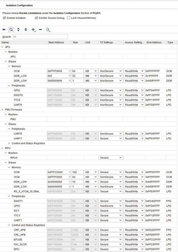
UltraScale MPSoC Architecture

UltraScale MPSoC Architecture
          This section discusses the hardware components in the UltraScale+ MPSoC architecture that are
          used to create subsystems and the protection units used to ensure FFI. At a high level,
          Zynq UltraScale+ MPSoCs consist of a processing system (PS) and programmable logic (PL).
          Zynq UltraScale+ MPSoC regions are also defined by power domains, including the full power
          domain (FPD) and low power domain (LPD) regions. Within these power domains are islands
          whose power can be controlled by the user.

          There are also four fundamental memory regions. These memory regions are the double data
          rate (DDR) memory, on-chip memory (OCM), tightly-coupled memory (TCM), and advanced
          eXtensible interface (AXI) block RAM in the PL. Access to memory is controlled by the memory
          controllers, direct memory access controllers (DMACs), memory management units (MMUs),
          and the XMPUs. The peripherals, mostly in the LPD, include devices in the input/output unit
          (IOU), and other devices such as the gigabit Ethernet MAC (GEM). The GEM and USB peripherals
          function as both master and slave AXI devices. Access to the peripherals can be dedicated or
          shared. However, when a peripheral is shared it is up to the user to arbitrate access. Isolation of
          the peripherals is provided using the XPPU.

          Figure 1 shows the location of the XMPUs and the XPPU in the Zynq UltraScale+ MPSoC. There
          are eight XMPUs. Six of the XMPUs protect transactions into the DDR, one protects the OCM,
          and one protects transactions into the FPD. There is one XPPU, which is located at the input to
          the LPD.

XAPP1320 (v3.2) October 26, 2020                                                   Send Feedback
                                                                                                            3
                                              www.xilinx.com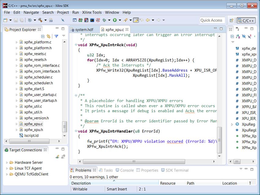
UltraScale MPSoC Architecture

X-Ref Target - Figure 1

                                                Figure 1:   Zynq UltraScale+ Architecture

                          The hardware provides other components that can be used for isolation: system memory
                          management unit (SMMU), AXI timeout blocks (ATBs), AXI isolation blocks (AIBs), and TZ. The
                          SMMU provides memory management for non-CPU masters such as direct memory access
                          controllers (DMACs). The SMMU provides isolation between two different processors that have
                          access to the same memory and the SMMU is commonly used in conjunction with hypervisors.
                          The ATBs ensure that AXI transactions for which there is not a slave response do not halt. The
                          AIBs facilitate the transition to a powered down state for regions that are powered down.
                          Powering down unused regions is important in isolation.

XAPP1320 (v3.2) October 26, 2020                                                               Send Feedback
                                                                                                                       4
                                                             www.xilinx.com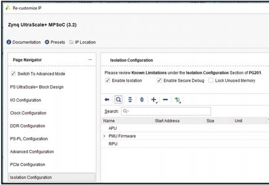
UltraScale MPSoC Architecture

          Several types of access control need to be used in conjunction with the protection units and TZ.
          AXI transactions can be either read or write. However, a section with code or data constants
          should not allow writes. To accommodate this isolation requirement, a memory region’s
          read/write permissions can be defined using TZ and the Xilinx protection units (XMPU and
          XPPU).

          Note: While the protection units use the master IDs to enforce isolation, TZ achieves this using the AXI
          AxProt bits.

          The Zynq UltraScale+ MPSoC APU is an Arm® v8 architecture and as such supports four
          exception levels. These exception levels are used to control privileges at the application level
          (i.e., each application has its own exception level). The Arm®v8 architecture exception levels
          (ELs) are exclusively for applications running on the APU. The RPU and PMU do not support
          them. However, the RPU supports modes to control privilege and it is similar to the concept of
          exception levels. For more information, see
          https://developer.arm.com/docs/den0024/latest/fundamentals-of-armv8/changing-exception-levels#
          BEIJHGDA.

          Powering down unused regions and islands is a valuable tool not just for isolation but also for
          general security and safety practices. A component cannot interfere with other components if it
          is powered down. Figure 2 shows an overview of the Zynq UltraScale+ MPSoC power islands.

XAPP1320 (v3.2) October 26, 2020                                                      Send Feedback
                                                                                                                 5
                                                www.xilinx.com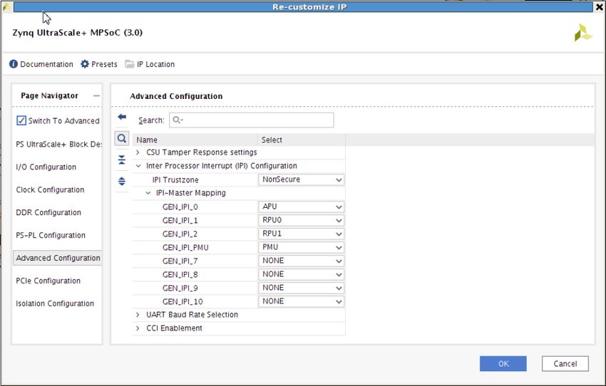
UltraScale MPSoC Architecture
X-Ref Target - Figure 2
PSIO {0:3} Power Battery Power Domain (BPD)
PLL Power Domains PS Auxiliary Power Domain PL Power Domain (PLPD)
VCC_PSBATT PL Power Domains for Multiple
Battery High-Performance I/O Low Power Domain (LPD)
PL Units
1.2 to 1.5V Full Power Domain (FPD) PMU software control
Power
Real
Supplies VCC_PSAUX good Time
Oscillator
Clock BBRAM
1.8V VCC_PSAUX
PS
1.8V VCC_PSADC SysMon eFUSE
VCCO_PSIO3 GIC ETM
1.8V to 3.3V System CSU PMU PS TAP
VCCO_PSIO2 IPI RPU
1.8V to 3.3V MIO 2 IOP OCM Ctrl MPCore
VCCO_PSIO1 LPD DMA
1.8V to 3.3V MIO 1
Interconnect and SLCR Bank 0 TCM A0
1.8V to 3.3V VCCO_PSIO0 MIO 0 Bank 1 TCM A1
VCC_PSINTLP USB 0 Bank 2 TCM B0
0.85 or 0.9V
USB 1 Bank 3 TCM B1
RPLL
1.2V VCC_PSPLL IOPLL
PL Arm DAP
debug APU Debug APU MPCore
APLL RPU debug
(SCU, GIC, CCI)
VPLL
DPLL L2 Cache
Interconnect and SLCR RAM
0.85V PS_MGTRAVCC
FPD DisplayPort CPU 0
1.8V PS_MGTRAVTT PS-GTR DMA
PCIe SATA
GPU pipeline CPU 1
VCC_PSINTFP CPU 2
0.85 or 0.9V VCC_PSINTFP_DDR CPU 3
GPU PP0
VCC_PSDDR_PLL GPU PP1
1.8V PLLs (x6) DDR Memory PCAP
Ports
PHY
1.1 to 1.5V VCCO_PSDDR Controller
DDRIOB
PL-FPD Isolation Wall PCAP-LPD Isolation Wall
VCCBRAM PL Fabric PL Configuration
0.85 or 0.9V BRAM
0.9V VCCINT_VCU VCU H.265, H.265 PL TAP
PL-LPD Isolation Wall
1.8V VCCADC
1.25V VREFP PL SYSMON
VCCAUX
DSP, LUT, Clks
1.8V (SYSMONE4)
VCCINT
PL Fabric
0.72, 0.85, or 0.9V
1.8V VCCAUX_IO PLPD
1.0 to 1.8V VCCO HP I/O
1.2 to 3.3V VCCO
HD I/O
0.9 to 1.8V GTH/GTY Supplies
SerDes 100 Gb Ethernet PCIe Gen3, 4 Interlaken
X22405-022719
Figure 2: Zynq UltraScale+ MPSoC Power Domains
XAPP1320 (v3.2) October 26, 2020 Send Feedback
6
www.xilinx.com
Isolation Tools

Isolation Tools
           The Zynq UltraScale+ MPSoC has many tools to aid in the development of an isolated design.
           The primary tools are discussed here.

           TrustZone
           The isolation methods in this application note rely on the use of protection units and TZ.
           Protection units provide isolation by detecting violating AXI transactions. Xilinx differentiates
           between the isolation provided by the protection units and isolation provided by TZ using the
           terms transaction isolation and state isolation, respectively. State isolation can be more
           comprehensive than transaction isolation. With state isolation, the processor, IP, memory, and
           interrupts in subsystems are assigned secure world (SW) or non-secure world (NSW) settings.
           The subsystem can context switch between SW and NSW states, thereby improving device
           utilization at the expense of software complexity.

           The reference design provides a critical framework to start using TZ. Because of its complexity,
           realization of all the advantages of TZ typically requires running a trusted execution
           environment (TEE) and support from a Xilinx ecosystem partner. For more information, see
           Isolate Security-Critical Applications on Zynq UltraScale+ Devices (WP516) [Ref 5]. In the
           included reference system (see Figure 13), the APU and its memory and peripherals are TZ
           non-secure while the RPU and PMU along with their dedicated memory and peripherals are TZ
           secure. While sharing is allowed (not typically recommended), the level must be consistent with
           the level of the master. For example, a non-secure master cannot access a secure memory or
           peripheral. However, a secure master can access either a secure or non-secure memory or
           peripheral.

           In the typical Arm use case, TZ uses hardware and software functionality to provide isolation. TZ
           defines SW and NSW operational states. Because functional safety (FS) applications sometimes
           have isolation requirements analogous to security applications, FS applications use the terms
           safety critical and non-safety critical in lieu of secure and non-secure, respectively. For brevity,
           the terms safe world and non-safe world will be used so as to keep the same acronym as the
           security context (secure world and non-secure world) because they are analogous.

           The intent is to ensure that safety critical functions cannot be corrupted by non-safety critical
           functions. In some, but not all TZ systems, the same CPU multiplexes between the SW and NSW
           because that is an efficient use of resources. This usually requires a relatively complex context
           switch. In the general case, however, trusted software runs in the SW using a standalone board
           support package (BSP) or a small operating system in the SW. NSW software runs on a rich
           operating system, often Linux, which generally has a wider attack surface.

           As an example, secure boot, secure firmware update, key management, reset control, power
           management, and other critical system functions are performed in the SW. Non-critical
           applications such as status reporting, non-essential analytics, and performance monitoring are
           performed in the NSW as a Linux application. The isolation provided by TZ minimizes the
           probability that a cyber attack or software bug in the NSW affects code or data in the SW.

XAPP1320 (v3.2) October 26, 2020                                                    Send Feedback
                                                                                                              7
                                               www.xilinx.com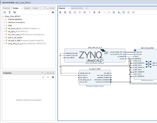
Isolation Tools

           Because the context switch between code running in a SW and a NSW is complex, it is easier if
           one CPU is statically configured to operate in the SW, and a second CPU is statically configured
           to operate in the NSW. With the number of CPUs provided in the Zynq UltraScale+ MPSoC, this
           is a viable option. As an example, the R5-0 can operate statically in the SW while the A53-0
           operates statically in the NSW.

           In TZ, masters, slaves, and memory are designated to function in either the SW or the NSW. A
           master in the SW has access to slave and memory belonging to both the SW and the NSW (i.e.,
           everything). A master in the NSW has access to slave and memory belonging only to the NSW.
           An access attempt by a NSW master to a SW peripheral or memory is not allowed. The illegal
           access will be rejected by the slave, generally with a SLVERR or DECERR response.

           The TZ hardware isolation on the Zynq UltraScale+ MPSoC uses the AxPROT[1] signal on the AXI
           bus as the filtering mechanism to determine if an access is legal. This is used on both the Arm
           advanced high-performance bus (AHB) and the advanced peripheral bus (APB) in the PS. The
           AXI interconnect IP used in the PL also supports AxPROT[1] allowing relatively straightforward
           TZ isolation in the PL(1). While the soft MicroBlaze processor and AXI IP do not support
           SW/NSW operating states, the custom logic to add the AxPROT signals is relatively simple.

           System Protection Units
           The Arm TrustZone technology tags the security level of each AXI transaction as described in
           more detail in TrustZone. The XMPU and the XPPU verify that a specific system master is
           explicitly allowed to access an address by assigning specific addresses ranges (memories and
           peripherals) to either the secure world or non-secure world TrustZone tags.

           XMPU
           Fundamental to any secure or functionally safe system is the isolation of memory. The XMPU
           gives the user the ability to partition user-defined regions of memory and allocate them to
           specific isolated subsystems. Figure 3 shows a functional diagram of the XMPU.

           1. It is up to the user to design cores that make use of these bits.

XAPP1320 (v3.2) October 26, 2020                                                  Send Feedback
                                                                                                          8
                                                            www.xilinx.com
Isolation Tools
X-Ref Target - Figure 3
0: LPD AXI
1: CCI AXI
Attribute
)3'6ZLWFK
Address 2: CCI AXI
3: HP0, DisplayPort
Poison
Poison 4: HP1, HP2
5: HP3, FPD_DMA
AXI OCM Switch
AXI
APB
FPD_XMPU PSLVERR Invalid Reg APB
IRQ Poisoned Trans OCM_XMPU and PSLVERR
or Invalid Reg DDR_XMPUx Invalid Reg
IRQ Poisoned Trans
Offset address + or Invalid Reg
[BASE] register
Original AxUser [Poison]
Address signal
$3%
PSLVERR
FPD_Sink
DECERR AXI
,54
AXI 3RLVRQHG7UDQV
RU,QYDOLG5HJ
IOP Switch
AXI 6HFXUH DDR {0:5}
(to Peripheral Slaves)
%ULGJH
OCM Memory
X22784-042519
Figure 3: XMPU Functionality
There are six XMPUs at the input to the DDRC interface and one XMPU at the input to the OCM.
There is also an XMPU at the input of the FPD interconnect for protection of FPD controllers
(SATA and PCIe®). The XMPU configuration generated by the Vivado tools is exported to the
first stage boot loader (FSBL). It is the FSBL that sets up the isolation configuration registers. As
an additional safety or security check, these registers can be read to verify their state. As part of
the Zynq UltraScale+ MPSoC functional safety software test library (STL), Xilinx provides the
capability to run self tests on the XMPU. These libraries are located in the Functional Safety
Lounge(1). Each XMPU protects up to 16 regions, with regions aligned on either 1 MB (DDR) or
4 KB (OCM) boundaries. For each region, the memory protection is based on two checks:
• The address of the transaction is within the region defined by START_ADDR and
END_ADDR.
• The master ID of the incoming transaction is allowed.
While it is possible to reconfigure these registers at runtime, it is not recommended for safe or
secure systems. Such systems typically require these registers to be locked. This is
recommended for the XPPU, but not for the XMPU. A conflict exists where locking the XMPU
configuration prevents any interrupts from it from being cleared (the register to clear interrupts
is also locked). Due to this conflict, the reference design added an additional subsystem, the
1. The Xilinx Functional Safety Lounge is a paid access repository for Functional Safety documentation and libraries. The no-fee
landing site is www.xilinx.com/applications/industrial/functional-safety.html.
XAPP1320 (v3.2) October 26, 2020 Send Feedback
9
www.xilinx.comIsolation Tools
PMU, to be the XMPU master. In this example, the XMPU configuration is not locked but is only
writable by the PMU subsystem. Framework code for the PMU is provided as an interrupt
handler. This framework allows for additional code to be added based upon the user’s error
reaction requirements.
Note: This conflict only exists for the XMPU. The XPPU can be locked without affecting the ability to clear
an interrupt.
The START_ADDR, END_ADDR, and master ID (MID) values are defined in the system setup and
readable in the XMPU register space. While the APU has a single master ID, the RPU has two
possibilities. If configured in lock-step mode, a single R5 master ID is used. If configured in
split mode, each R5 has its own master ID. If an access violates any of the protection criteria, the
XMPU prevents this access by applying a poisoning method.
If an illegal transaction is attempted, the XMPU asserts AxUser[10] but the transaction is passed
to the memory controller. This mechanism is referred to as poison by attribute. The transaction
is gated by the end point, not the XMPU itself. In the case of the DDR, the user has choices of
how to deal with the invalid transaction (none of which actually allow it). While there is a second
way of poisoning the transaction (by address), poisoning by attribute is recommended for the
XMPU.
Optionally, the XMPU can generate an interrupt such that an error reaction can be included in
the interrupt handler. See the “System Protection Unit” chapter in the Zynq UltraScale+ MPSoC
Technical Reference Manual (UG1085) [Ref 2] for additional information on the XMPU.
XPPU
The XPPU allows for protecting peripherals, message buffers, inter-processor interrupts (IPI)
and communications, as well as Quad SPI flash memory. It is best deployed at the system “choke
points” where all traffic to the protected objects will pass through, thus maximizing the
protection coverage. In comparison with the XMPU, the XPPU uses finer grained address
matching and provides more address apertures. Additionally, where the XMPU discourages the
use of address poisoning in lieu of attribute poisoning, the XPPU only allows address poisoning.
The address poisoning approach is shown in Figure 3 on the left side. The violating access is
deviated to a certain memory area that is reserved for this purpose. A master ID list is used to
define the masters that are allowed to access peripherals. Eight of the 20 master IDs are
predefined. An aperture permission list (APL) specifies permissions on peripheral addresses
that masters can access. Permissions are based on master ID.
A functional diagram of the XPPU is shown in Figure 4.
XAPP1320 (v3.2) October 26, 2020 Send Feedback
10
www.xilinx.comIsolation Tools
X-Ref Target - Figure 4
Data
Address Permission Aperture
Decode RAM Info
ADDR
APB APB Permission
Interface Check
ID Match
Master ID
Lookup
Control
Registers
AXI AXI
AxADDR
poison
AxADDR AxUSER
AxUSER AxPROT
AxPROT
X22786-042519
Figure 4: XPPU Functional Diagram
Both the Zynq UltraScale+ MPSoC Processing System LogiCORE IP Product Guide (PG201) [Ref 3]
and Zynq UltraScale+ MPSoC Technical Reference Manual (UG1085) [Ref 2] provide additional
information on the master ID and aperture permission lists, permission checking, and error
handling.
Memory Management and Protection Units
In addition to the Xilinx Protection Units, the Arm Cortex R5 and A53 systems have typical
memory protection (memory protection unit and memory management unit, respectively)
allowing for additional access control within each processor complex. A highlight is given here
but more detail can be found in the respective technical reference manuals.
The memory protection unit (MPU) of the Arm Cortex R5 allows for creating 0, 12, or 16
memory regions. This allows for individual protection attributes to be set for each region. Each
region is defined by the base address and size. Overlapping of regions is allowed where sharing
a specific address space is desired. Additionally, the the memory management unit (MMU) in
the ARMv8 architecture supports two-stage translation, which allows the users’ OS and
hypervisor to have their own translation stages.
Each Arm Cortex A53 allows for more granular region definition. Rather than specify the
number of regions, it specifies the granularity of a region (4 KB or 64 KB). Each address region
is assigned its own ID (ASID).
The Xilinx system memory management unit (SMMU) extends the MMU capability of the
processor cores into the rest of the Zynq UltraScale+ MPSoC architecture for any other
master/DMA capable devices using six translation buffer units (TBUs). A high-level usage
diagram can be seen in Figure 5.
XAPP1320 (v3.2) October 26, 2020 Send Feedback
11
www.xilinx.comIsolation Tools
X-Ref Target - Figure 5
APU MPCore
CPU 0
CPUx CPU 1
CPU 2
GPU Cache Cache Non- Non-
CPU 3
Masters Coherent Coherent coherent coherent
MMU Stage MMU Master 1 Master n Master 1 Master n
1 and 2 Stage 1
L1 Cache Cache
Interconnect Interconnect
Coherent Interconnect SMMU TBU SMMU TBU
SMMU TBU
L2 Cache Stage 1 Stages 1 Stages 1
and 2 and 2
Cache Coherent Interconnect (CCI)
DDR Memory Subsystem
X22407-022719
Figure 5: Example of SMMU System Locations
AXI Isolation Block
Originally intended to isolate a master from its slave in preparation for powering down, the AXI
isolation blocks (AIBs) can be used to enhance isolation. These blocks are spread throughout
the entire PS of the device. They can be configured to block undesired accesses and generate
a SLVERR response when an illegal access is attempted. The control registers for the AIB can be
protected by the XPPU.
Exception Levels
The ARMv8 architecture allows for setting up four exception levels (EL0 – EL3) allowing for
additional access control within the Arm A53 complex. These exception levels are best
described as follows:
• EL0: Lowest software execution privilege (Sometimes referred to as the unprivileged
execution level). User applications typically run at this level.
• EL1: First true “privileged” level. Operating systems typically run at this level. This level
provides basic support for the non-secure state.
• EL2: Higher level of privilege adding support for processor virtualization. Hypervisors
typically run at this level. This level provides support for processor virtualization.
• EL3: Most privileged level adding support for a secure state. Secure monitor code runs at
this level. For the Zynq UltraScale+ MPSoC, this is the Arm Trusted Firmware (ATF).
XAPP1320 (v3.2) October 26, 2020 Send Feedback
12
www.xilinx.comIsolation Tools
A graphical depiction of this structure (along with TrustZone) is shown in Figure 6.
X-Ref Target - Figure 6
Non-secure State Secure State
App 0 App n App 0 App n App 0 App n
EL0
AArch64 or AArch64 or AArch64 or AArch64 or AArch64 or AArch64 or
AArch32 AArch32 AArch32 AArch32 AArch32 AArch32
SVC
Supervisor (Guest OS1) Supervisor (Guest OS2) Supervisor (Secure OS)
EL1
AArch64 or AArch32 AArch64 or AArch32 AArch64 or AArch32
HVC
Hypervisor Mode
EL2
AArch64 or AArch32
SMC
EL3 Secure Monitor Mode
X22408-022719
Figure 6: Armv8 Exception Levels with TrustZone
Interprocessor Communication
Most systems, even with isolation, require some sort of communication between subsystems.
As an example, the APU subsystem can support an Ethernet interface that receives and
transmits data from or to a server for both the APU and RPU subsystems. The RPU subsystem
can generate log files and transmit them to the APU subsystem, which then transfers them to
the server using Ethernet. Similarly, a server can send commands to the RPU subsystem using
the APU subsystem Ethernet, which then uses the inter-subsystem communication mechanism
to transfer the command to the RPU subsystem.
The Zynq UltraScale+ MPSoC provides IPI buffers to support interprocessor communication
between the APU, RPU, and PMU subsystems. The exchange between the APU, RPU, and PMU
subsystems uses 32-byte request and response buffers. Figure 7 shows one specific example
using interprocessor communication between the APU and RPU subsystems using IPI in the
reference design. This is just one example using IPI. Communication can be initiated by all
participants of the IPI system. See the Zynq UltraScale+ MPSoC Technical Reference Manual
(UG1085) [Ref 2] for more information on using IPI.
XAPP1320 (v3.2) October 26, 2020 Send Feedback
13
www.xilinx.comIsolation Tools
X-Ref Target - Figure 7
APU Subsystem RPU Subsystem
A53 R5-0
IPI Registers
Write Request Read
Read Response Write
Read Request Write
Write Response Read
X22421-030119
Figure 7: Interprocessor Communication Using IPI
The protocol for the message exchange is for the requesting subsystem (APU) to trigger an
interrupt to the receiving subsystem (RPU). The interrupt triggering subsystem fills the data in
the IPI channel’s request buffer. The RPU interrupt receiving master reads the content of the
request buffer. If the interrupt receiving master needs to provide response data to the interrupt
triggering master, the response buffer is used. The response buffer is read by the triggering
master (APU).
The Zynq UltraScale+ MPSoC provides eleven IPI channels for inter-subsystem communication.
Out of the eleven, channels 3 – 6 are dedicated to the PMU, and the remaining are configurable
as masters. The inter-subsystem communication is supported in hardware and uses the xipipsu
device driver. Each channel provides six registers used to trigger the interrupt and check status.
Figure 8 shows the hardware support for interprocessor interrupts in the Vivado design suite.
For the purposes of this lab, the default settings will be used.
XAPP1320 (v3.2) October 26, 2020 Send Feedback
14
www.xilinx.comIsolation Tools
X-Ref Target - Figure 8
X19460-030119
Figure 8: Vivado Design Suite IPI Communication Setup
Handling Interrupts with the PMU
The XMPU and XPPU optionally generate an interrupt when there is a memory or peripheral
access violation. The system can be set up so that the interrupt is connected to either the APU
GIC, RPU GIC, or AXI INTC, allowing an interrupt handler to be implemented by the APU, RPU,
or PMU.
The error reaction in the interrupt handler is defined by the system requirements. For example,
in one system, the reaction might be to power down the system and require intervention to
restart the system. In another system, in which availability is a prevalent requirement, the
system might remain functional. In this case, the error reaction might be to log the error, notify
a server for possible scheduled maintenance, and continue operation.
Figure 9 shows the PMU FW code for handling an error. The file shown is xpfw_xpu.c and can
be found under the BSP tree in SDK. The message (shown later) is printed from the
XPfw_Xpu_IntrHandler function. This handler can be modified to implement the required error
reaction.
XAPP1320 (v3.2) October 26, 2020 Send Feedback
15
www.xilinx.comIsolation Tools
X-Ref Target - Figure 9
X19463-062617
Figure 9: PMU FW Code for Error Handling
Fault Injection/Application Fault Error Handling
For functional safety and security systems, it is not sufficient to add safe or secure features
without testing that such features work. For functional features, this is straight forward (if it
runs it works). However, for security or safety related features, system functionality is proof of
nothing because such features might only be noticeable in the presence of a fault. Because it is
not practical to wait for a fault to happen, it is typically necessary to inject faults into the
system. In the example design, it will be necessary to prove isolation by attempting to violate it.
To verify isolation between multiple isolation regions, faults will be injected by writing code to
perform illegal memory and peripheral accesses through TZ protected XMPU and XPPU gates,
and verifying that such accesses are blocked and notification is given to the system. Additional
symbols will be added to the PMU code to enable detailed error messaging while additional
error handling routines will be added to the application code to allow it to run through an
isolated violation. However, these symbols are optional and only for outputting error messages
to the UARTs. They are not required or even desired in a real-world system.
To allow the application that is performing the illegal reads and writes, it is necessary to
construct an error handler to deal with it. This allows the application to run through the fault
rather than end abruptly. How a system handles interrupts is entirely up to the developer and
XAPP1320 (v3.2) October 26, 2020 Send Feedback
16
www.xilinx.comIsolation Tools
the system requirements for interrupt handling. This example is best used for demonstration
and as a placeholder for the actual user code.
The example application running in the APU domain generates two types of interrupts: sync and
error aborts. The actual error type depends on the corresponding transaction type (read or
write). Each must have their own handler. The error type depends on the transaction type: read
or write. The requirements for two types of errors comes from the Arm architecture itself, not
the Xilinx-specific implementation. Figure 10 shows the error handler code for both. For sync
aborts, the code sets a Boolean variable, letting the main routine know an abort happened. It
then steps forward one instruction to prevent a loop when returning to the same offending
statement. Error aborts simply log that an abort happened. The application determines if the
statement “passed” or “failed” depending upon the value of this Boolean. Figure 11 shows the
code to register the custom handlers. A similar handler for the RPU system was also generated
but it only required the sync error handler because only one interrupt type is generated in that
system. These handlers are for demonstration purposes and not what would be expected in a
real-world system. How to handle such errors is up to the developer and the requirements of
the system being developed.
X-Ref Target - Figure 10
X22388-022819
Figure 10: Application Interrupt Handlers
X-Ref Target - Figure 11
X22389-022719
Figure 11: Application Interrupt Handler Registration
XAPP1320 (v3.2) October 26, 2020 Send Feedback
17
www.xilinx.comKnown Limitations to Isolation
Known Limitations to Isolation
There are some limitations to isolation that the user must be aware of. These limitations are
documented here.
A-53 cores
There are use cases where it is desirable to physically isolate each core of the quad A-53
processor complex. However, unlike the cores of the R-5 processor complex, each A53 core has
the same master ID. This makes it impossible to use features like XMPU and XPPU to isolate
them. If such isolation is desired, it must to be implemented at a software level, using either a
TEE (Trusted Execution Environment) or a hypervisor.
CCI-400
While useful to keep transactions coherent, it must be pointed out that the CCI-400 IP is
capable of mastering its own transactions. This creates a potential conflict as it generates these
transactions using the same master ID as the R5_0 processor core. This can result in isolation
errors. The Zynq UltraScale+ MPSoC Technical Reference Manual (UG1085) [Ref 2] recommends
adding the R5_0 to the access list of the memory region whose transactions are being mastered
by the CCI-400. While this addresses the access error, it is not typically practical in an isolation
use case. The following options can resolve this issue:
1. Add R5_0, as the Zynq UltraScale+ MPSoC Technical Reference Manual (UG1085) [Ref 2]
suggests, to the memory region whose transactions are mastered by the CCI-400. This
prevents the error but has implications to isolation that must be dealt with.
2. Move the R5_0 application over to the R5_1 core and keep R5_0 either unused or capable of
being in the same isolation region as the memory region whose transactions are driven by
the CCI-400.
3. Disable Cache Coherency for the region being protected by an XMPU.
XMPU Configuration Locking
The XMPU lock bit over protects the configuration; it protects the bit that clears interrupts. This
makes it impractical to lock the configuration as any access violation would not be able to be
addressed as the interrupt cannot be cleared. To address this limitation, it is recommended that
the user make the PMU the master and make it its own isolation system. While the XMPU
configuration may not be locked, it is protected from access by any master other than the PMU.
XAPP1320 (v3.2) October 26, 2020 Send Feedback
18
www.xilinx.comIsolation Reference Design
Isolation Reference Design
The first step in developing a system on the Zynq UltraScale+ MPSoC is defining the
functionality in terms of the architecture. This means defining the tasks performed in the APU,
RPU, and PL. In most systems, there is a joint requirement that the subsystems be isolated to
perform their tasks without interference.
It is quite common for subsystems to require some level of communication between them. To
support this and maintain isolation between them, there are two common methods:
inter-processor interrupt (IPI) and shared memory. IPI relies on a common message buffer and
integrated interrupt system while shared memory creates a partition of memory shared
between the two subsystems. In IPI, the Zynq UltraScale+ MPSoC architecture handles the
notification of the messages while shared memory requires the user to create a similar
notification architecture. Each method has its merits depending upon user requirements.
In some cases, there are reasons for subsystems to share resources. Device configuration is a
good example where non-volatile memory (NVM) stores the boot image for all subsystems,
loaded at power-up. Another example is the DDR controller (DDRC). While it is possible to add
an AXI DDRC in the PL, this increases the resources used, which increases the cost. The isolation
is increased, but the effect of using the added DDRC resources on reliability is less clear.
When using development boards such as the ZCU102 or UltraZed-EG, there might be
constraints in the resources used by each subsystem. The multiplexed I/O (MIO) and device
board interfaces might present resource limitations that do not exist on a custom board. This
reference design specifically targets the ZCU102 development board.
Software Patch Requirements (2019.1/2019.2)
There is an issue discovered in 2019.1 and 2019.2 where the warm restart function conflicts with
isolation. To support warm restart, the PMU copies the FSBL to DDR. This causes two key
conflicts:
• It requires the PMU to read OCM in this reference design, to which it does not have access.
• Violates security tenets if authentication and/or encryption are used for the FSBL.
° Copies the FSBL outside of the chip in DDR without encrypting it.
° Copies the hash of the FSBL for integrity but stores that hash outside in DDR as well.
For more information, see AR73475. The following patches are required for this lab:
• 0001-sw_apps-zynqmp_fsbl-Fix-logic-in-writing-FSBL-runnin.patch
• 0002-sw_apps-zynqmp_pmufw-Make-FSBL-copy-as-user-option.patch
When installed, open the xpfw_config.h file and change the value of
USE_DDR_FOR_APU_RESTART_VAL from (1) to (0) as shown in Figure 12. While it is possible to
make this change on a project by project basis, failure to disable this option (which is enabled
by default) can cause isolation errors in most isolated systems. It is recommended to disable it
XAPP1320 (v3.2) October 26, 2020 Send Feedback
19
www.xilinx.comIsolation Reference Design
in the patch repository rather than in each PMU firmware project. The xpfw_config.h file can
be found at /embeddedsw/lib/sw_apps/zynqmp_pmufw/src.
X-Ref Target - Figure 12
X23827-041320
Figure 12: Altered USE_DDR_FOR_APU_RESTART_VAL Option in 2019.1 Patch
Note: For more information on installing patches, see Answer Record 72710. While a patch for 2019.2 is
shown above, this lab targets 2019.1. 2019.2 uses Vitis (not SDK) and will be addressed in a future
version of this document.
XAPP1320 (v3.2) October 26, 2020 Send Feedback
20
www.xilinx.comIsolation Reference Design
System Overview
Figure 13 shows the reference system, which consists of three subsystems. In this design, the
APU subsystem is considered a non-secure system (colored green) while the PMU and RPU
subsystems are both considered secure systems (colored red). Where non-secure regions are
shared with secure masters they are colored both red and green.
X-Ref Target - Figure 13
PMU Subsystem
TTC_0 CRF_APB
TTC_1 CRL_APB
RPU
SDWT_0 APU Subsystem RPU Subsystem SDWT_1 EFUSE
IOU_SLCR
GPIO UART_0 UART_1 I2C_1
DDR OCM R5_0 ATCM
0x0000_0000 0xFFFC_0000
0xFFE0_0000
0x01FF_FFFF 0xFFFF_0000
0xFFE0_FFFF
0xFFFF_FFFF
0x4000_0000
0x40FF_FFFF
Secure Subsystem
Non-secure Subsystem
Non-secure Subsystem (shared with Secure Subsystem)
0x6000_0000
0x600F_FFFF
X22375-070420
Figure 13: Isolation Reference Design
The reference system partitions the PS as follows:
• The DDR is split into three regions. The APU subsystem owns addresses 0x0000_0000 to
0x01FF_FFFF and shares 0x6000_0000 to 0x600F_FFFF with the RPU subsystem. The
region 0x4000_0000 to 0x40FF_FFFF is owned by the RPU subsystem.
• OCM is split in two regions. Address range 0xFFFC_0000 to 0xFFFC_0000 is owned by
the RPU subsystem, while the remaining addresses (0xFFFF_0000 to 0xFFFF_FFFF) are
shared between the APU and RPU subsystems.
• The R5 owns the entire R5_0_ATCM region.
• The APU subsystem owns TTC0 and SWDT0, while sharing GPIO with the RPU subsystem
and UART0 with the PMU subsystem. The RPU subsystem owns TTC1, SWDT1, and I2C1, and
shares UART1 with the PMU subsystem.
XAPP1320 (v3.2) October 26, 2020 Send Feedback
21
www.xilinx.comIsolation Reference Design
A more detailed address map is shown in Table 1.
Table 1: System Address Map
APU Subsystem
A53-0 NSW
OCM 0xFFFF_0000 64 KB NSW R/W
DDR_LOW 0x0000_0000 32 MB NSW R/W
DDR_LOW 0x6000_0000 1 MB NSW R/W
UART0 NSW R/W
GPIO NSW R/W
SWDT0 NSW R/W
TTC0 NSW R/W
RPU Subsystem
R5-0 SW
OCM 0xFFFC_0000 192 KB SW R/W
OCM 0xFFFF_0000 64 KB NSW R/W
DDR_LOW 0x4000_0000 16 MB SW R/W
DDR_LOW 0x6000_0000 1 MB NSW R/W
R5_0_ATCM_GLOBAL SW R/W
SWDT1 SW R/W
UART1 SW R/W
TTC1 SW R/W
I2C1 SW R/W
GPIO NSW R/W
CRF_APB SW R/W
CRL_APB SW R/W
RPU SW R/W
EFUSE SW R/W
IOU_SLCR SW R/W
PMU Subsystem
PMU SW
UART0 NSW R/W
UART1 SW R/W
CRF_APB SW R/W
DDR_XMPU0_CFG SW R/W
DDR_XMPU1_CFG SW R/W
DDR_XMPU2_CFG SW R/W
DDR_XMPU3_CFG SW R/W
DDR_XMPU4_CFG SW R/W
XAPP1320 (v3.2) October 26, 2020 Send Feedback
22
www.xilinx.comIsolation Reference Design
Table 1: System Address Map (Cont’d)
DDR_XMPU5_CFG SW R/W
FPD_SLCR SW R/W
FPD_XMPU_CFG SW R/W
LPD_XPPU SW R/W
CRL_APB SW R/W
EFUSE SW R/W
IOU_SLCR SW R/W
LPD_SLCR SW R/W
OCM_XMPU_CFG SW R/W
RPU SW R/W
For secure and safe systems using XMPU and XPPU for isolation, it is desirable to protect their
configuration to prevent errant software or an adversary from modifying these settings and
compromising the intended isolation. This can be done with either of the following:
• The psu_protection_lock funtion in the PMU Firmware can be called.
• The XMPU/XPPU lock bits can be set.
• The FPD_XMPU protection can be used.
However, due to the conflict described in XMPU, it is not recommended to lock the XMPU. It is
better, as demonstrated in the reference design, to add the XMPU to a secure master such as
the PMU.
Building The Hardware Platform
Isolation in the UltraScale+ MPSoC family is rooted in hardware. As such, the configuration of
the hardware is the first step in building the isolated system. The following steps outline how to
set up the hardware to create three isolated subsystems and use the XPMU, XPPU, and
TrustZone hardware to isolate each subsystem. The first step is to create the base hardware
platform to build upon.
After starting the Vivado tools, click Create Project in the Quick Start page to open the New
Project wizard. Use the information below to make selections in each of the wizard screens:
• Create a New Vivado Project
No options. Select Next.
• Project Name
Project name: ps_isolation_lab
Project location: c:/temp/xapp1320_2019.1/ (referred to later as
)
Create project subdirectory: checked
XAPP1320 (v3.2) October 26, 2020 Send Feedback
23
www.xilinx.comIsolation Reference Design
• Project Type
Check Example Project.
• Select Project Template
Select Base Zynq UltraScale+ MPSoC.
• Default board or part
Select Zynq UltraScale+ ZCU102 Evaluation Board.
• New Project Summary
No options. Select Finish.
Afterwards your screen will look like Figure 14.
X-Ref Target - Figure 14
X22376-022819
Figure 14: Initial IP Integrator Diagram
Now that a base hardware platform has been generated it is necessary to refine that definition
for isolation.
1. Double-click the Zynq UltraScale+ IP (zynq_ultra_ps_e_0 instance).
2. Check Switch To Advanced Mode in the Page Navigator of the new pop-up window.
3. Select Isolation Configuration in the Page Navigator.
4. Check Enable Isolation at the top of the Isolation Configuration page.
The Secure Subsystem is a baseline subsystem for secure booting. The tools create this system
as a baseline for you to start with. For ease of documentation, this reference design builds its
own system. However, you can start with the Secure Subsystem to save time. Note that in 2019.1
XAPP1320 (v3.2) October 26, 2020 Send Feedback
24
www.xilinx.comIsolation Reference Design
and 2019.2, there was not an option to change that name. Future software releases may allow a
name change.
5. Delete the Secure Subsystem.
6. Create two additional isolation subsystems (RPU and APU):
a. Click on the button to Add New Subsystem named RPU.
b. Click on the button to Add New Subsystem named APU.
When complete, your window should look like Figure 15.
X-Ref Target - Figure 15
X22377-030119
Figure 15: Re-customize IP Window: Base Isolation Subsystems
Before customizing the isolation systems, it is important to understand the three check boxes
shown in Figure 15 as they have significant ramifications for isolated systems:
Enable Isolation
This is the key enabling function for isolation. You must check this for enabling an isolation
setup in the reference design.
Enable Secure Debug
Enabling Secure Debug adds specific components to each isolated subsystem. Specifically, it
adds DAP and CoreSight components as masters. Deselecting this option would prohibit JTAG
access to any secure subsystem. This reference design keeps this option checked by default as
it is expected to be used as a training guide for using isolation and debug. For fielded systems,
however, care must be taken on the use of debug logic and debug access points. It is
recommended that such components be under the control of the most secure (trusted)
subsystem in your design.
Lock Unused Memory
Enabling this option restricts the use of all memory locations (memory and peripherals) not
explicitly defined by the isolation setup. In a secure system this would typically be checked.
XAPP1320 (v3.2) October 26, 2020 Send Feedback
25
www.xilinx.comIsolation Reference Design
However, be mindful that there are operations in a system that are not always obvious to you
and could be impacted by this parameter. For example, when loading authenticated and/or
encrypted images after boot (a partial bitfile), the system must access the CSU, eFuse, and
potentially BBRAM register space. If these are not explicitly added to the secure subsystem
performing this action, then it is blocked by the setting of the Lock Unused Memory option. Use
of this option for this reference design is not tested and is therefore assumed to be unchecked.
It is now necessary to add masters to each isolation subsystem.
1. Right-click APU, select Add Master, and search/select APU.
2. Right-click RPU, select Add Master and search/select RPU0.
° Accept the default secure setting.
Now that each subsystem has a master, it is necessary to assign the slave components to the
APU subsystem.
1. Add slave peripherals to the APU subsystem:
a. Right-click APU to Add Slaves and search/select GPIO keeping NonSecure TZ setting.
Note: This is shared with the RPU subsystem.
b. Right-click APU to Add Slaves and search/select SWDT0 keeping NonSecure TZ
setting.
c. Right-click APU to Add Slaves and search/select TTC0 keeping NonSecure TZ setting.
d. Right-click APU to Add Slaves and search/select UART0 keeping NonSecure TZ setting.
2. Add slave memory to the APU subsystem:
a. Right-click APU to Add Slave and search/select OCM:
- Start address: 0xFFFF0000
- Size: 64 KB
- TZ settings: NonSecure
Note: This is shared with the RPU subsystem.
b. Right-click APU to Add Slave and search/select DDR_LOW:
- Start address: 0x0
- Size: 32 MB
- TZ settings: NonSecure
c. Right-click APU to Add Slave and search/select DDR_LOW:
- Start address: 0x60000000
- Size: 1 MB
- TZ settings: NonSecure
Note: This is shared with the RPU subsystem.
XAPP1320 (v3.2) October 26, 2020 Send Feedback
26
www.xilinx.comIsolation Reference Design
With the APU subsystem fully populated it is now necessary to assign the slave components to
the RPU subsystem.
Note: When building this subsystem some resources might appear in red when initially added. This is
due to a temporary security conflict which gets resolved when the subsystem is fully defined. There
should be no conflicts (no red) when completed.
1. Add slave peripherals to the RPU subsystem:
a. Right-click RPU to Add Slaves and search/select GPIO keeping NonSecure TZ setting.
Note: This is shared with the APU subsystem.
b. Right-click RPU to Add Slaves and search/select I2C1 selecting Secure TZ setting.
c. Right-click RPU to Add Slaves and search/select SWDT1 selecting Secure TZ setting.
d. Right-click RPU to Add Slaves and search/select TTC1 selecting Secure TZ setting.
e. Right-click RPU to Add Slaves and search/select UART1 selecting Secure TZ setting.
2. Add slave registers to the RPU subsystem (Necessary because FSBL executes on RPU):
a. Right-click RPU to Add Slaves and search/select CRF_APB selecting Secure TZ setting.
b. Right-click RPU to Add Slaves and search/select CRL_APB selecting Secure TZ setting.
c. Right-click RPU to Add Slaves and search/select EFUSE selecting Secure TZ setting.
d. Right-click RPU to Add Slaves and search/select IOU_SLCR selecting Secure TZ setting.
e. Right-click RPU to Add Slaves and search/select RPU selecting Secure TZ setting.
3. Add slave memory to the RPU subsystem:
a. Right-click RPU to Add Slave and search/select OCM:
- Start address: 0xFFFC0000
- Size: 192 KB
- TZ settings: Secure
b. Right-click RPU to Add Slave and search/select OCM:
- Start address: 0xFFFF0000
- Size: 64 KB
- TZ settings: NonSecure
Note: This is shared with the APU subsystem.
c. Right-click RPU to Add Slave and search/select DDR_LOW:
- Start address: 0x40000000
- Size: 16 MB
- TZ settings: Secure
d. Right-click RPU to Add Slave and search/select DDR_LOW:
- Start address: 0x60000000
XAPP1320 (v3.2) October 26, 2020 Send Feedback
27
www.xilinx.comIsolation Reference Design
- Size: 1 MB
- TZ settings: NonSecure
e. Right-click RPU to Add Slave and search/select R5_0_ATCM_GLOBAL:
- Start address:
- Size:
- TZ settings: Secure
At this stage the APU and RPU subsystems have been fully populated. However, the PMU
subsystem needs a few modifications in order for the error messaging to reach the outside
world.
1. Add slave peripherals to the PMU Firmware subsystem:
a. Right-click PMU Firmware to Add Slaves and search/select UART0 keeping NonSecure
TZ setting.
Note: This is shared with the APU subsystem.
b. Right-click PMU Firmware to Add Slaves and search/select UART1 keeping Secure TZ
setting.
Note: This is shared with the RPU subsystem.
2. At this stage the Isolation Configuration window should look like Figure 16.
XAPP1320 (v3.2) October 26, 2020 Send Feedback
28
www.xilinx.comIsolation Reference Design
X-Ref Target - Figure 16
X22379-022619
Figure 16: Re-customize IP Window: PMU Complete
3. Select OK.
The Vivado tools automatically generated the address map for the AXI IP in the sample design.
However, because we have now changed the platform due to isolation restrictions, it is
necessary to re-map that IP.
1. In the Address Editor tab of the Block Design window, simultaneously select both
axi_bram_ctrl_0 and axi_gpio_0 segments.
a. Right-click and select Unmap Segment.
XAPP1320 (v3.2) October 26, 2020 Send Feedback
29
www.xilinx.comIsolation Reference Design
2. In the Address Editor, select the Data segment.
a. Right-click and select Auto Assign Address.
Note: The PL peripherals axi_bram_ctrl_0 and axi_gpi_0 do not support the protection mechanism and
are accessible by all AXI masters.
Now that a platform design has been created, it is necessary to implement the design to
generate all the necessary hardware files for SDK.
1. In the Flow Navigator window, click Generate Bitstream and select Yes.
a. Click Save if requested.
2. Click OK in the Launch Runs popup window.
a. This process takes several minutes depending on the capability of the machine it is
running on.
3. Click Cancel in the Bitstream Generation Completed popup window. It is not necessary to
open the implemented design.
It is now necessary to export the newly created hardware platform and launch SDK.
1. Select File > Export > Export Hardware to export the hardware platform.
2. Select Include bitstream and click OK on the Export Hardware popup window.
a. Keep the default Local to Project setting.
3. Select File > Launch SDK.
a. Keep the default settings of Local to Project for both the Exported location and
Workspace.
b. Select OK.
Creating Demonstration Software
This section describes how to use SDK to create software that runs on the isolated system
created in the previous section. To test the features previously discussed, five software projects
will be created. These projects and their function are listed in Table 2.
Table 2: Software Projects
Project Function
pmu_firmware PMU firmware: event handler
r5_fsbl FSBL running on R5_0
rpu_ipi Interprocessor interrupt code running on the R5_0
rpu_fault_injection Fault injection code running on the R5_0
apu_ipi Interprocessor interrupt code running on APU_0
apu_fault_injection Fault injection code running on the APU_0
XAPP1320 (v3.2) October 26, 2020 Send Feedback
30
www.xilinx.comIsolation Reference Design
Because this lab runs multiple projects simultaneously, it is necessary to manually modify the
linker scripts for each project. Failure to do so would result in memory collisions. For the
purposes of this lab, however, the linker scripts will be imported along with the code (excluding
FSBL and PMU projects where the defaults are acceptable).
Creating the FSBL project
The FSBL runs at boot time and loads the PS software projects and, if present, the PL bitstream.
This section provides the steps necessary for creating this project.
1. Select File > New > Application Project.
a. Project Name: r5_fsbl
b. OS Platform:
c. Hardware Platform:
d. Processor: psu_cortexr5_0
e. Language:
f. Compiler:
g. Hypervisor Guest:
h. Board Support Package:
2. Click Next.
a. Available Templates: Zynq MP FSBL
3. Click Finish.
Creating the PMU project
It is necessary to include the PMU firmware project for the following reasons:
• The PMU firmware project is required for any MPSoC processor system.
• Due to the issue with XMPU interrupts, it is desirable to have an independent secure master
owning the protection units (XMPU and XPPU).
1. Select File > New > Application Project.
a. Project Name: pmu_firmware
b. OS Platform:
c. Hardware Platform:
d. Processor: psu_pmu_0
e. Language:
f. Compiler:
g. Hypervisor Guest:
XAPP1320 (v3.2) October 26, 2020 Send Feedback
31
www.xilinx.comIsolation Reference Design
h. Board Support Package:
2. Click Next.
a. Available Templates: ZynqMP PMU Firmware
3. Click Finish.
Because the PMU owns the protections units and will be the primary system level error handler,
it is necessary to add four build variables:
• ENABLE_EM: Enables the error manager of the PMU.
• ENABLE_SCHEDULER: Prerequisite for use of ENABLE_EM (see the PMU Firmware Build
Flags table in Zynq UltraScale+ MPSoC Software Developer Guide (UG1137) [Ref 4]).
• XPU_INTR_DEBUG_PRINT_ENABLE: Enhanced debug print information.
• XPFW_DEBUG_DETAILED: Enhanced debug print information.
Note: These variables are not necessary in a fielded system. They are only necessary for external
messaging and adding more detail to that messaging. In a fielded system, they would not normally be
set.
1. In the SDK Project Explorer window, right-click pmu_firmware and select C/C++ Build
Settings.
2. Under C/C++ Build, select Settings.
3. Under MicroBlaze gcc compiler, select Symbols.
4. In the Defined Symbols area, click the symbol.
a. Enter ENABLE_EM and click OK.
5. In the Defined Symbols area, click the symbol.
a. Enter ENABLE_SCHEDULER and click OK.
6. In the Defined Symbols area, click the symbol.
a. Enter XPU_INTR_DEBUG_PRINT_ENABLE and click OK.
7. In the Defined Symbols area, click the symbol.
a. Enter XPFW_DEBUG_DETAILED and click OK.
8. In the SDK Project Explorer window, click OK.
The Properties for pmu_firmware window should look like Figure 17.
XAPP1320 (v3.2) October 26, 2020 Send Feedback
32
www.xilinx.comIsolation Reference Design
X-Ref Target - Figure 17
X23828-041320
Figure 17: PMU Build Symbols
Creating the APU Inter-processor Interrupt Project
In an isolated system there is still a need for one subsystem to communicate with another
subsystem. One method to do this safely and securely is to utilize the IPI system. This is
demonstrated using two projects: the first runs in the APU subsystem, while the second runs in
the RPU subsystem. This project targets the APU subsystem.
Because the actual source code is delivered with this lab, it is necessary to create an empty
project in which the code will be imported.
1. Select File > New > Application Project.
a. Project Name: apu_ipi
b. OS Platform:
c. Hardware Platform:
d. Processor: psu_cortexa53_0
e. Language:
f. Compiler:
g. Hypervisor Guest:
XAPP1320 (v3.2) October 26, 2020 Send Feedback
33
www.xilinx.comIsolation Reference Design
h. Board Support Package:
2. Click Next.
a. Available Templates: Empty Application.
3. Click Finish.
Now that an empty project has been created, the delivered code can be imported.
1. In the Project Explorer windows, expand apu_ipi and select src.
2. Right-click src and select Import.
3. Expand General in the Import window, select File System and click Next.
4. Use the Browse button to navigate to
\software\c\ipiTest\apu, click OK.
5. Click apu in the left-hand pane, verify all files in the right-hand pane are selected, and click
Finish. If prompted to overwrite files, select Yes.
Creating the RPU Inter-processor Interrupt Project
In an isolated system there is still a need for one subsystem to communicate with another
subsystem. One method to do this safely and securely is to utilize the IPI system. This is
demonstrated using two projects: the first runs in the APU subsystem, while the second runs in
the RPU subsystem. This project targets the RPU subsystem.
Because the actual source code is delivered with this lab, it is necessary to create an empty
project in which the code will be imported.
1. Select File > New > Application Project.
a. Project Name: rpu_ipi
b. OS Platform:
c. Hardware Platform:
d. Processor: psu_cortexr5_0
e. Language:
f. Compiler:
g. Hypervisor Guest:
h. Board Support Package:
2. Click Next.
a. Available Templates: Empty Application.
3. Click Finish.
Now that an empty project has been created, the delivered code can be imported.
1. In the Project Explorer windows, expand rpu_ipi and select src.
XAPP1320 (v3.2) October 26, 2020 Send Feedback
34
www.xilinx.comYou can also read