User Manual DA16600 FreeRTOS Example Application Manual - UM-WI-052 - Dialog ...
←
→
Page content transcription
If your browser does not render page correctly, please read the page content below
User Manual
      DA16600 FreeRTOS Example
          Application Manual
                                   UM-WI-052

Abstract
This document describes the FreeRTOS based DA16600 SDK example applications using the
DA16600 module, which includes the DA16200 and the DA14531.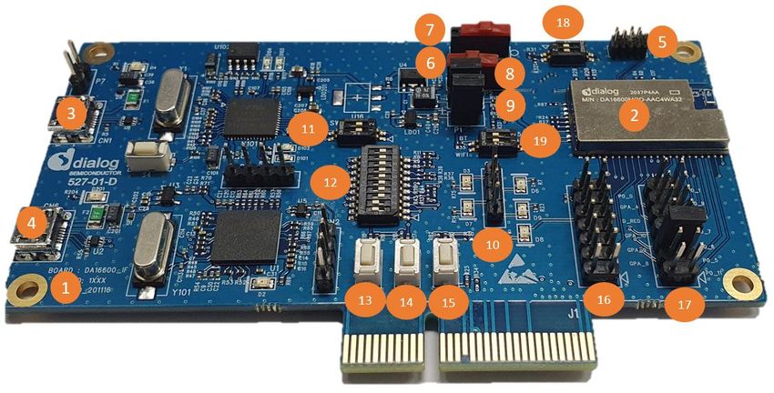
UM-WI-052
DA16600 FreeRTOS Example Application Manual

Contents
Abstract ................................................................................................................................................ 1
Contents ............................................................................................................................................... 2
Figures .................................................................................................................................................. 3
1    Terms and Definitions ................................................................................................................... 5
2    References ..................................................................................................................................... 6
3    Introduction.................................................................................................................................... 7
     3.1 DA16600 Module Evaluation Board ...................................................................................... 7
     3.2 Example 1: Bluetooth® LE Assisted Wi-Fi Provisioning ........................................................ 8
     3.3 Example 2: Bluetooth® LE Firmware OTA Download via Wi-Fi ............................................ 9
     3.4 Example 3: Gas Leak Detection Sensor ............................................................................... 9
     3.5 Example 4: DA14531 Peripheral Driver Examples ............................................................. 10
     3.6 Example 5: TCP Client in DPM ........................................................................................... 10
     3.7 Example 6: IoT Sensor Gateway ........................................................................................ 11
4    Software Build and Flashing Guide ........................................................................................... 12
     4.1 SFLASH Memory Map ........................................................................................................ 12
     4.2 Build the DA16200 Software ............................................................................................... 13
     4.3 Build DA14531 Software ..................................................................................................... 14
          4.3.1    Install Keil ............................................................................................................ 14
          4.3.2    Build a Project ...................................................................................................... 15
     4.4 Program SFLASH and Run ................................................................................................. 16
          4.4.1    Create a DA14531 Image .................................................................................... 16
                   4.4.1.1         Use mkimage.exe ............................................................................ 16
                   4.4.1.2         Create a Multi-Part Image ............................................................... 17
                   4.4.1.3         Create a Single Image ..................................................................... 19
          4.4.2    Program SFLASH with .ttl File ............................................................................. 20
          4.4.3    Program SFLASH without .ttl File ........................................................................ 22
     4.5 Run DA16600 with JTAG .................................................................................................... 23
          4.5.1    Run DA16200 with JTAG..................................................................................... 23
          4.5.2    Run DA14531 with JTAG..................................................................................... 23
5    DA16600 Example Test Procedure ............................................................................................ 27
     5.1 Test Environment Setup...................................................................................................... 27
          5.1.1   Wi-Fi Access Point ............................................................................................... 27
          5.1.2   Bluetooth® LE Peers ............................................................................................ 27
                  5.1.2.1     Bluetooth® LE Mobile App ................................................................ 27
                  5.1.2.2     Bluetooth® LE Sensors..................................................................... 27
          5.1.3   PC: to Control Bluetooth® LE Peers and DA16600 Boards ................................. 28
          5.1.4   DA16600 EVB Boards ......................................................................................... 28
     5.2 Example 1: Bluetooth® LE Assisted Wi-Fi Provisioning ...................................................... 28
     5.3 Example 2: Bluetooth® LE Firmware OTA Download via Wi-Fi .......................................... 29
     5.4 Example 3: Gas Leak Detection Sensor ............................................................................. 33
     5.5 Example 4: DA14531 Peripheral Driver Example ............................................................... 34
          5.5.1   Test Environment Setup ...................................................................................... 34
User Manual                                                       Revision 1.0                                                         12-May-2021

CFR0012                                                                 2 of 86                                          © 2021 Dialog Semiconductor
UM-WI-052
DA16600 FreeRTOS Example Application Manual
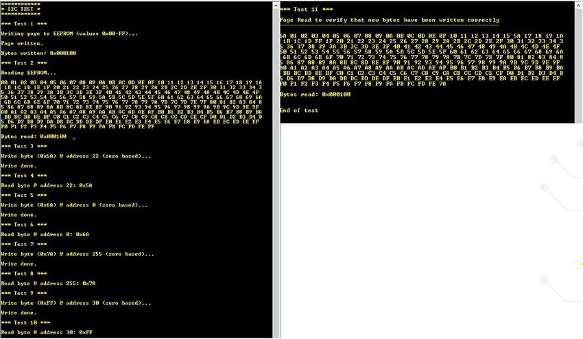
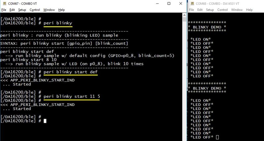
5.5.2 User Commands .................................................................................................. 37
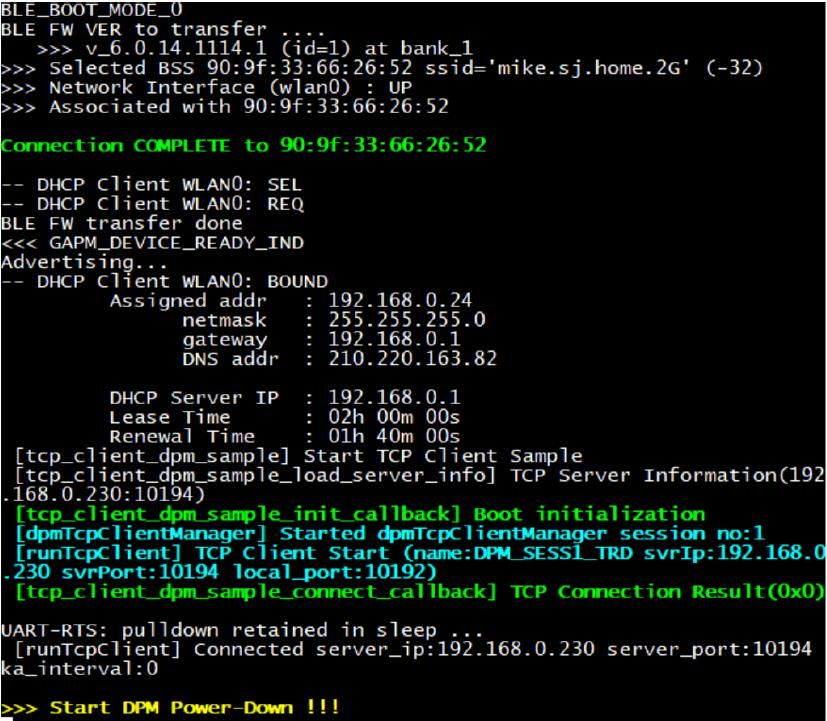
5.6 Example 5: TCP Client in DPM ........................................................................................... 47
5.6.1 Test Environment Setup ...................................................................................... 47
5.6.2 Test Steps ............................................................................................................ 47
5.7 Example 6: IoT Sensor Gateway ........................................................................................ 49
6 Code Walkthrough ...................................................................................................................... 54
6.1 SDK Source Structure ......................................................................................................... 54
6.2 Startup and GTL Initialization .............................................................................................. 55
6.3 DA16600 Application Development .................................................................................... 57
6.4 Examples ............................................................................................................................ 57
6.4.1 Bluetooth® LE Assisted Wi-Fi Provisioning .......................................................... 57
6.4.1.1 Application Build and Run ............................................................... 57
6.4.1.2 Application Initialization ................................................................... 57
6.4.1.3 GTL Message Flow.......................................................................... 60
6.4.1.4 Wi-Fi Service GATT Database Design ............................................ 61
6.4.1.5 Application Protocol Between a Bluetooth® LE Peer and Wi-Fi
SVC Application ............................................................................... 63
6.4.2 ®
Bluetooth LE Firmware OTA Download via Wi-Fi .............................................. 66
6.4.3 Gas Leak Detection Sensor ................................................................................. 67
6.4.3.1 User Interface .................................................................................. 67
6.4.3.2 Operation ......................................................................................... 67
6.4.4 DA14531 Peripheral Driver Example ................................................................... 71
6.4.4.1 Build ................................................................................................. 71
6.4.4.2 Example Code Flow......................................................................... 71
6.4.4.3 About GPIO PINs in DA14531 ......................................................... 76
6.4.5 TCP Client in DPM ............................................................................................... 76
6.4.5.1 Build and Run .................................................................................. 76
6.4.5.2 Application Flow............................................................................... 76
6.4.6 IoT Sensor Gateway ............................................................................................ 79
6.4.6.1 Build and Run .................................................................................. 79
6.4.6.2 Application Initialization ................................................................... 80
6.4.6.3 GTL Message Flow.......................................................................... 82
Revision History ................................................................................................................................ 85
Figures
Figure 1: DA16600 (Combo) EVB ......................................................................................................... 7
Figure 2: JTAG Pin Connection ............................................................................................................. 7
Figure 3: Bluetooth® LE Assisted Wi-Fi Provisioning ............................................................................ 8
Figure 4: Standalone Gas Leak Detection Sensor ................................................................................ 9
Figure 5: DA14531 Peripheral Device Control .................................................................................... 10
Figure 6: DA16600 TCP Client in DPM ............................................................................................... 10
Figure 7: IoT Sensor Gateway............................................................................................................. 11
Figure 8: Project View ......................................................................................................................... 14
Figure 9: Keil – Build ........................................................................................................................... 15
Figure 10: Bluetooth® LE FW Image Generation – Preparation .......................................................... 18
Figure 11: Bluetooth® LE FW Image Generation – Multi-Part Image .................................................. 19
User Manual Revision 1.0 12-May-2021
CFR0012 3 of 86 © 2021 Dialog Semiconductor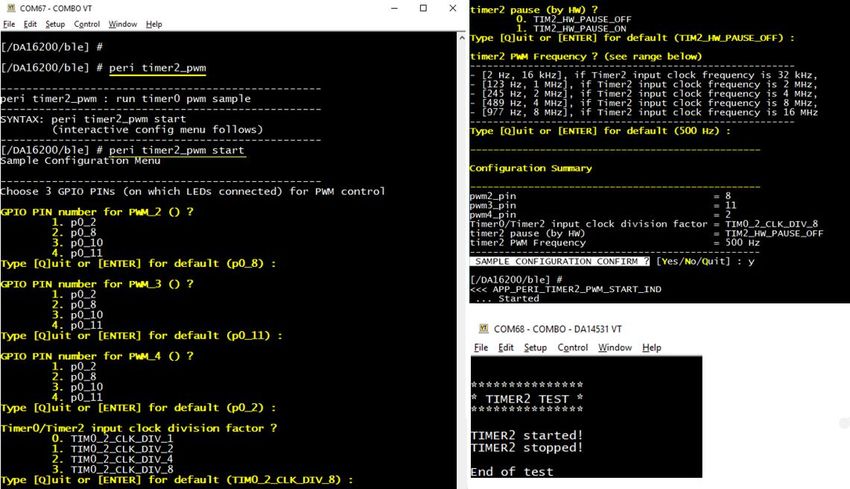
UM-WI-052
DA16600 FreeRTOS Example Application Manual

Figure 12: Bluetooth® LE FW Image Generation – Single Image........................................................ 20
Figure 13: DA16600 Images and .ttl Files to Program ........................................................................ 21
Figure 14: Steps to Program by the .ttl File ......................................................................................... 21
Figure 15: Tera Term ........................................................................................................................... 22
Figure 16: Keil – Option ....................................................................................................................... 24
Figure 17: Keil – Debug ....................................................................................................................... 24
Figure 18: Keil – JTAG Device ............................................................................................................ 25
Figure 19: Tera Term – DA16200 Waiting for DA14531 to Connect .................................................. 25
Figure 20: Keil – Start Debugger ......................................................................................................... 26
Figure 21: Keil – Evaluation Mode Dialog Box .................................................................................... 26
Figure 22: Keil – Run ........................................................................................................................... 26
Figure 23: Tera Term – Advertising Successful .................................................................................. 26
Figure 24: Dialog Wi-Fi Provisioning App ............................................................................................ 28
Figure 25: Provisioning Application – Custom Command ................................................................... 31
Figure 26: DA16600 EVB Config. 1 ..................................................................................................... 34
Figure 27: DA16600 EVB Config. 2 ..................................................................................................... 35
Figure 28: DA16600 EVB Config. 3 ..................................................................................................... 35
Figure 29: Peri Blinky .......................................................................................................................... 37
Figure 30: Peri Systick ......................................................................................................................... 38
Figure 31: Peri Timer0_gen ................................................................................................................. 39
Figure 32: Peri Timer0_buz 1/2 ........................................................................................................... 40
Figure 33: Peri Timer0_buz 2/2 ........................................................................................................... 40
Figure 34: Peri Timer2_pwm ............................................................................................................... 41
Figure 35: Peri Batt_lvl ........................................................................................................................ 41
Figure 36: Peri I2c_eeprom ................................................................................................................. 42
Figure 37: Peri I2c_eeprom Read/Write .............................................................................................. 42
Figure 38: Peri Spi_flash – Wrong Image Warning ............................................................................. 43
Figure 39: Correct Image Version for Peri Spi_flash Sample ............................................................. 43
Figure 40: Peri Spi_flash ..................................................................................................................... 43
Figure 41: Peri Spi_flash Read/Write .................................................................................................. 44
Figure 42: Peri Quad_dec – Wrong Image Warning ........................................................................... 44
Figure 43: Correct Image Version for Peri Quad_dec Sample ............................................................ 45
Figure 44: Peri Quad_dec – Start ........................................................................................................ 45
Figure 45: Peri Quad_dec Stop ........................................................................................................... 46
Figure 46: Peri GPIO Set/Get .............................................................................................................. 47
Figure 47: TCP Client in DPM Sleep ................................................................................................... 48
Figure 48: TCP Client – Wakeup from DPM Sleep ............................................................................. 48
Figure 49: Sensor_1/2 Bluetooth® LE Peer Sample Implementation (in Python) ................................ 53
Figure 50: Source Folder Structure ..................................................................................................... 55
Figure 51: GTL Message Sequence Chart – Initialization................................................................... 60
Figure 52: GTL Message Sequence Chart – Connect and Write........................................................ 61
Figure 53: GTL Message Sequence Chart – Read ............................................................................. 61
Figure 54: GTL Message Sequence Chart – Initialization................................................................... 82
Figure 55: GTL Message Sequence Chart – Provisioning Mode ........................................................ 82
Figure 56: GTL Message Sequence Chart – Scan and Connect ........................................................ 84
Figure 57: GTL Message Sequence Chart – Enable Sensor Posting ................................................. 84
Figure 58: GTL Message Sequence Chart – Disable Sensor Posting ................................................ 84

User Manual                                                   Revision 1.0                                                      12-May-2021

CFR0012                                                             4 of 86                                        © 2021 Dialog Semiconductor
UM-WI-052
DA16600 FreeRTOS Example Application Manual

1     Terms and Definitions
AP            Access Point
API           Application Programming Interface
BD            Bluetooth Device
COM           Communication Port
CTS           Clear to Send
DHCP          Dynamic Host Configuration Protocol
DPM           Dynamic Power Management
EVB           Evaluation Board
FW            Firmware
HW            Hardware
GAP           Generic Access Profile
GATT          Generic Attribute Profile
GPIO          General Purpose Input/Output
GTL           Generic Transport Layer
HTTP          Hypertext Transfer Protocol
HTTPS         Hypertext Transfer Protocol Secure
I2C           Inter-Integrated Circuit (bus)
IDE           Integrated Development Environment
iOS           iPhone Operating System
IoT           Internet of Things
JLINK         JTAG Link
JSON          JavaScript Object Notation
JTAG          Joint Test Action Group
LED           Light emitting diode
LAN           Local Area Network
OTA           Over the Air
OTP           One Time Programmable
PWM           Pulse Width Modulation
RBP           Raspberry Pi
RF            Radio Frequency
RTOS          Real Time Operating System
RTS           Request to Send
SDK           Software Development Kit
SoC           System on Chip
SPI           Serial Peripheral Interface
SVC           Service
SW            Software
TCP           Transmission Control Protocol
UART          Universal Asynchronous Receiver/Transmitter
UDP           User Datagram Protocol
USB           Universal Serial Bus
UUID          Universally Unique Identifier
Wi-Fi         Wireless Fidelity

User Manual                         Revision 1.0                      12-May-2021

CFR0012                                5 of 86              © 2021 Dialog Semiconductor
UM-WI-052
DA16600 FreeRTOS Example Application Manual

XIP               Execute in Place

2      References
[1]   UM-WI-046, D16200 FreeRTOS SDK Programmer Guide, User Manual, Dialog Semiconductor
[2]   UM-B-143, Dialog External Processor Interface, User Manual, Dialog Semiconductor
[3]   DA14531 Getting Started Guide
[4]   DA14531 SW Platform Reference
[5]   DA16200 FreeRTOS SDK Start-up Guide, User Manual, Dialog Semiconductor
[6]   UM-WI-044, DA16600 Provisioning the Mobile App for Android/iOS

User Manual                           Revision 1.0                             12-May-2021

CFR0012                                   6 of 86                    © 2021 Dialog Semiconductor
UM-WI-052
DA16600 FreeRTOS Example Application Manual

3       Introduction
The Dialog DA16600 module is comprised of the DA16200 (Wi-Fi) and DA14531 (Bluetooth® LE)
SoC. The two chips exchange the data with each other through the GTL interface. This document
describes the test steps and code walkthrough of four example applications with DA16600.

3.1       DA16600 Module Evaluation Board
Figure 1 shows the hardware configuration of the DA16600 EVB.

                                   Figure 1: DA16600 (Combo) EVB

DA16600 EVB has the following components:
1.    Main Board: DA16600 module (DA16600MOD-AAC) is installed.
2.    DA16600MOD-AAC Wi-Fi and Bluetooth® LE Combo Module.
3.    USB Port: UART0 is for debugging, UART1 is for testing.
4.    USB Port: to debug, connect directly to DA14531, but do not use this port for normal operation.
5.    JTAG Pin: allows connecting to I-jet (a JTAG debugger from IAR). See Figure 2.
      ○ Pin 7 is keyed with a white plug, so Pin 7 should be removed on EVB

                                    Figure 2: JTAG Pin Connection

6. RTC Wake up2 key: a switch to wake up the board from Sleep mode.
7. RTC Power key: a switch to turn on/off the module.
8. Pin (P2): a jumper to measure current at the Wi-Fi part. For normal operation, this pin should be
   shorted.
      ○ Pull out the Short Pin cap and connect the jumper wire to measuring equipment
User Manual                                 Revision 1.0                                  12-May-2021

CFR0012                                         7 of 86                         © 2021 Dialog Semiconductor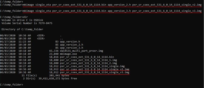
UM-WI-052
DA16600 FreeRTOS Example Application Manual

9. Pin (P1): a jumper to measure current at Bluetooth® LE part. For normal operation, this pin
   should be shorted.
      ○ Pull out the Short Pin cap and connect the jumper wire to measuring equipment
10. Connector CN4: GPIO test purpose connector.
      ○ To test GPIO in J2 and J14, connect to LED by this connector
11. Switch SW3: a switch to connect directly to DA14531 and use UART to check Bluetooth ® LE
    performance.
    ○ This switch is set to Off in normal operation
12. Switch SW7: a multipurpose switch.
      ○ This switch is set to Off in normal operation
13. Switch S2: factory reset button using GPIOA7.
    ○ Set to ON at Pin2 of SW7 to use this switch
14. Switch S1: WPS button using GPIOA6.
      ○ Set to ON at Pin1 of SW7 to use this switch
15.   Switch S3: reset button of DA14531 in Test mode.
16.   Connector J2: GPIO connector.
17.   Connector J14: GPIO connector.
18.   Switch SW4: a switch to control RF switch in DA16600MOD at Test mode.
19.   Switch SW5: a switch to check current consumption using a power meter kit.

3.2       Example 1: Bluetooth® LE Assisted Wi-Fi Provisioning
In this example, the DA16600 module can be used as a "Wi-Fi door lock" where Wi-Fi plays the main
role, and Bluetooth® LE assists with "Wi-Fi Provisioning" for the product's initial setup (Out-of-Box).
A Bluetooth® LE peer provisioning mobile application (used in Android/IOS) is required in this
example (see Section 6.4.1.5), it allows users to configure Wi-Fi (such as the SSID, password, server
information, and so on for user's Wi-Fi router) into the DA16600 module.

                        Figure 3: Bluetooth® LE Assisted Wi-Fi Provisioning

User Manual                                 Revision 1.0                                  12-May-2021

CFR0012                                         8 of 86                         © 2021 Dialog Semiconductor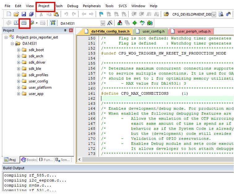
UM-WI-052
DA16600 FreeRTOS Example Application Manual

3.3       Example 2: Bluetooth® LE Firmware OTA Download via Wi-Fi
After Wi-Fi is successfully configured and up and running in Operational mode, for example, the Wi-
Fi door lock function is running, the DA16600 device can receive notifications from a service server
on the Internet/Cloud that there is new firmware (Wi-Fi firmware or Bluetooth® LE firmware). Upon
receipt via Wi-Fi, the DA16600 module can download the new firmware from an OTA server and
store the data in its flash memory and trigger the firmware update.

3.4       Example 3: Gas Leak Detection Sensor
This example assumes a DA16600 module that interacts with a standalone Gas Leak Detection
Sensor. This virtual gas density check sensor is attached to a Bluetooth® LE chip for sensing work in
Low-power mode that periodically checks the gas density level.
When a gas leak is detected by the virtual sensor, Bluetooth® LE wakes up Wi-Fi, creates a "gas
leak" event and sends the event to the Wi-Fi chip, then posts the "leak" event to a cloud server to
notify a user of the event.

                         Figure 4: Standalone Gas Leak Detection Sensor

User Manual                                Revision 1.0                                   12-May-2021

CFR0012                                        9 of 86                          © 2021 Dialog Semiconductor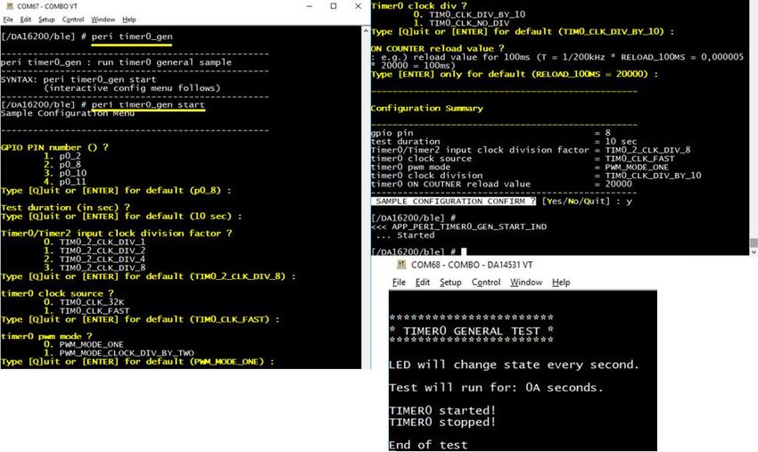
UM-WI-052
DA16600 FreeRTOS Example Application Manual

3.5       Example 4: DA14531 Peripheral Driver Examples
This example shows how to use the DA14531/peripherals controlled by driver functions and
commands in DA16200 through the GTL interface. The peripherals in DA14531 can be used as the
GPIO, I2C, SPI, PWM, and so on.

                         Figure 5: DA14531 Peripheral Device Control

3.6       Example 5: TCP Client in DPM
In this example, the DA16600 module runs TCP client in Low-power mode. DA16200 stays in DPM
mode and DA14531 stays in extended Sleep mode. This example shows that the DA16600 module
in Sleep mode can receive a Wi-Fi packet from a network peer or Bluetooth® LE data from a
Bluetooth® LE peer. After either Wi-Fi packet or Bluetooth® LE data is handled, DA16600 enters
Sleep mode again to save power.

                             Figure 6: DA16600 TCP Client in DPM

User Manual                             Revision 1.0                                12-May-2021

CFR0012                                     10 of 86                      © 2021 Dialog Semiconductor
UM-WI-052
DA16600 FreeRTOS Example Application Manual
3.7 Example 6: IoT Sensor Gateway
In this example, the DA16600 module plays the role of a gateway device for multiple Bluetooth® LE
temperature sensors.
A Bluetooth® LE sensor posts the current temperature value periodically via the notify function of
Bluetooth® LE. The Bluetooth® LE chip of the DA16600 module gathers the information and asks Wi-
Fi to post notifications periodically to a service server in the cloud.
NOTE
Three connections are available with DA16600.
Figure 7: IoT Sensor Gateway
User Manual Revision 1.0 12-May-2021
CFR0012 11 of 86 © 2021 Dialog SemiconductorUM-WI-052
DA16600 FreeRTOS Example Application Manual
4 Software Build and Flashing Guide
The DA16600 module consists of two SoC chips – the DA16200 and DA14531. The firmware images
of the two chips are stored in the SPI flash memory of the DA16600 module. The flash memory is
only accessible by DA16200 and not accessible by DA14531 directly. This means that the firmware
image for DA14531 should be written in the flash and the DA16200 reads it and transferred to
DA14531 at runtime by DA16200.
The list of firmware images needed to run each SoC chip:
DA16200: Wi-Fi chip
● Two image files:
○ FBOOT image: secondary bootloader
○ FRTOS image: main operation software into which user applications are built
● Code storage memory
○ SFLASH of DA16200
DA14531: Bluetooth® LE chip
● Single image file:
○ Main image: main operation software into which user applications are built
● Code storage memory
○ SFLASH of DA16200 or OTP memory (32 kB allocated for OTP image)
– OTP memory can be used to burn a default image but cannot update the firmware
anymore for DA14531 after it is burnt, the OTA firmware update is not available either. If
an OTA firmware update is needed, then the SFLASH of the DA16200 should be used
4.1 SFLASH Memory Map
The following code shows the SFLASH memory map defined for the DA16600 module.
.\core\bsp\driver\include\DA16200\da16200_map.h
/*
*
* 0x0000_0000 2nd Bootloader 0x22000 ( 136 KB )
* 0x0002_2000 Boot Index 0x1000 ( 4 KB )
* 0x0002_3000 RTOS #0 0x1BF000 ( 1788 KB )
* 0x001E_2000 RTOS #1 0x1C0000 ( 1792 KB )
* 0x003A_2000 Debug/RMA Certificate 0x1000 ( 4 KB )
* 0x003A_3000 TLS Certificate Key #0 0x4000 ( 16 KB )
* 0x003A_7000 TLS Certificate Key #1 0x4000 ( 16 KB )
* 0x003A_B000 NVRAM #0 0x1000 ( 4 KB )
* 0x003A_C000 NVRAM #1 0x1000 ( 4 KB )
* 0x003A_D000 User Area #1 0x52000 ( 332 KB )
* 0x0040_0000 END_ADDR
*/
...
#define SFLASH_USER_AREA_1_START 0x003AD000
#define SFLASH_USER_AREA_START SFLASH_USER_AREA_1_START
/* BLE Firmware */ Bluetooth® LE firmware is stored
#define SFLASH_BLE_FW_BASE (SFLASH_USER_AREA_START )
/* 0x003AD000 ~ 0x003BD000, 64KB */
User Manual Revision 1.0 12-May-2021
CFR0012 12 of 86 © 2021 Dialog SemiconductorUM-WI-052
DA16600 FreeRTOS Example Application Manual
The map has two image banks allocated for each type of the DA16200 image and the DA14531
image. For more details for the memory map, see Section 3 of the DA16200 FreeRTOS SDK
Programmer Guide [1].
The next sections describe how to build software for the DA16200 and the DA14531 based on the
memory map above.
4.2 Build the DA16200 Software
To build the DA16600 SDK based on the FreeRTOS, the Eclipse IDE environment is required. Refer
to the DA16200 FreeRTOS SDK Start-up Guide [5] for Eclipse installation and Startup Guide first to
install and to get ready to build.
To test the Example 1, 2, or 3, make changes below in .\customer\config\user_custom_config.h
("DA16200_SW_1"). If security needs to be enabled, then enable __WIFI_SVC_SECURITY__
in .\customer\user_main\include\config_generic_sdk_da16600.h ("DA16200_SW_1b"):
● DA16200_SW_1
○ Enable __BLE_PERI_WIFI_SVC__
○ Disable the other sample defines (__BLE_XXX)
● DA16200_SW_1b
○ Enable __BLE_PERI_WIFI_SVC__
○ Disable the other sample defines (__BLE_XXX)
○ Enable __WIFI_SVC_SECURITY__
NOTE
The difference between DA16200_SW_1b and DA16200_SW_1 is when a Bluetooth® LE peer mobile
application tries to connect to the DA16600 (with DA16200_SW_1b), a pairing procedure is requested.
Two pairing modes are depending on the test mobile phone's Bluetooth® authentication capability
configuration:
● Legacy Pairing: the mobile application may show an input box and ask a user to enter a passkey that
can be found on the display of the DA16600 HW, and then a user needs to enter the exact passkey on the
test smartphone to successfully connect to the DA16600
● Secure Connection Pairing (SC Pairing): the mobile application may show a PIN code on the test mobile
and ask a user to compare the PIN code with the one printed on the display of the DA16600 HW. If the
PIN code match, click the OK button to connect the DA16600 to test the mobile application
The DA16600 example currently can save bond information for up to ten Bluetooth® LE peers.
Once bond information is put in the test mobile phone, the test mobile phone's Bluetooth® LE peer application
can be connected to the DA16600 without the need to repeat the pairing process. If either party lost the
pairing credential, the pairing process starts again when a user reconnects.
For Example 4, make the following changes to build DA16200_SW_2:
● Enable __BLE_PERI_WIFI_SVC_PERIPHERAL__
● Disable the other sample defines (__BLE_XXX)
For Example 5, make the following changes to build DA16200_SW_3:
● Enable __BLE_PERI_WIFI_SVC_TCP_DPM__
● Disable the other sample defines (__BLE_XXX)
For Example 6, make the following changes to build DA16200_SW_4:
● Enable __BLE_CENT_SENSOR_GW__
● Disable the other sample defines (__BLE_XXX)
User Manual Revision 1.0 12-May-2021
CFR0012 13 of 86 © 2021 Dialog SemiconductorUM-WI-052
DA16600 FreeRTOS Example Application Manual
Figure 8: Project View
To build the SDK based on FreeRTOS, right-click the sdk_main folder and select build project in the
list. After the build, in the .\img folder, there should be the following two DA16200 images:
● DA16600_FRTOS-GEN01-01-XXXXX-000000.img
● DA16600_FBOOT-GEN01-01-XXXXX-000000_XXX.img
4.3 Build DA14531 Software
The DA14531 software (Bluetooth® LE SW) used in the DA16600 SDK is based on the DA14531
SDK version 6.0.14.1114. To build the DA14531 software for the examples, a user needs a DA14531
SDK 6.0.14.1114 that is specifically adapted for DA16600. It is available
in .\util\da14531_sdk_xxx.zip.
Depending on which example users want to test, it needs to use a different example Bluetooth® LE
target project.
NOTE
The example projects mentioned below are not included in the original 6.0.14.1114. The projects below
(Prj1_proxr and Prj2_proxm) are created and modified for the four examples of DA16600.
For Examples 1, 2, and 3, use the Prj1_proxr project:
[DA14531_SDK_ROOT]\projects\target_apps\ble_examples\prox_reporter_sensor_ext_coex\Kei
l_5\prox_reporter_ext.uvprojx
For Example 4, use the Prj2_proxm project:
[DA14531_SDK_ROOT]\projects\target_apps\ble_examples\prox_monitor_aux_ext_coex\Keil_5\
prox_monitor_ext.uvprojx
4.3.1 Install Keil
For information on the Keil installation, see the corresponding section in http://lpccs-docs.dialog-
semiconductor.com/UM-B-117-DA14531-Getting-Started-With-The-Pro-Development-
Kit/05_Software_Development_Tools/Software_Development_Tools.html.
User Manual Revision 1.0 12-May-2021
CFR0012 14 of 86 © 2021 Dialog SemiconductorUM-WI-052
DA16600 FreeRTOS Example Application Manual
NOTE
The Keil IDE download URL is https://www.keil.com/download/product/.
4.3.2 Build a Project
To build a project in Keil:
1. In Keil, go to Project > Open Project, and then select the .uvprojx file.
Keil opens the project. For example, open
[DA14531_SDK_ROOT]\projects\target_apps\ble_examples\prox_reporter_sensor_ext_coex
\Keil_5\prox_reporter_ext.uvprojx.
2. Go to Project > Clear Targets.
3. Click Rebuild.
Figure 9: Keil – Build
After Prj1_proxr or Prj2_proxm is built with the Keil IDE, there is a .bin file in directory
[DA14531_SDK_ROOT]\projects\target_apps\ble_examples\prox_reporter_sensor_ext_coex\Keil_5\
out_DA14531\Objects\.
User Manual Revision 1.0 12-May-2021
CFR0012 15 of 86 © 2021 Dialog SemiconductorUM-WI-052
DA16600 FreeRTOS Example Application Manual
NOTE
To quickly test an example without building the DA14531 software, use the pre-built DA14531 image. See the
folder [DA16600_SDK_ROOT]\img\DA14531_x\:
● DA14531_1 – Prj1_proxr
● DA14531_2 – Prj2_proxm
If a user wants to run multiple DA16600 boards at the same time (with the same example project), a user
needs to build the DA14531 projects with different BD addresses. Ensure that each DA16600 board's BD
address is unique to avoid an address conflict. A user can change the BD address of the DA14531 in the
da1458x_config_advanced.h file (search for CFG_NVDS_TAG_BD_ADDRESS at the bottom of the
source).
4.4 Program SFLASH and Run
4.4.1 Create a DA14531 Image
After code build, the images can be found in the following folder:
[DA14531_SDK_ROOT]\projects\target_apps\ble_examples\prox_reporter_sensor_ext_coex\Kei
l_5\out_img\.
or
[DA14531_SDK_ROOT]\projects\target_apps\ble_examples\prox_monitor_aux_ext_coex\Keil_5\
out_img\.
The images required in the examples are generated automatically by create_img.bat in the Keil
project folder above. But to create images manually, users can use the tool named mkimage.exe
available in the [DA16600_SDK_ROOT]\util\ble_img_creator\ folder of the DA16600 SDK.
NOTE
The mkimage.exe included in the DA16600 SDK is built in Visual Studio 2019 release mode. Therefore, if a
user runs mkimage.exe from the command prompt window and gets some errors like "… vcruntime140.dll is
missing …", then install Microsoft Visual C++ Redistributable for Visual Studio 2015, 2017 and 2019 (see
https://support.microsoft.com/en-us/help/2977003/the-latest-supported-visual-c-downloads).
If the PC still does not run mkimage.exe, a user can also build the tool. The tool mkimage.exe can be built in
either GCC or MSVC environment.
The mkimage tool source folder is: [DA14531_SDK_ROOT]\utilities\mkimage\.
For GCC: for example, Linux, Cygwin, and so on.
[DA14531_SDK_ROOT]\utilities\mkimage\gcc: run "make" at the prompt.
For Windows: for example, Visual Studio
[DA14531_SDK_ROOT]\utilities\mkimage\: add mkimage.c to a win32 console application project and build.
4.4.1.1 Use mkimage.exe
There are two types of .img files to be created with mkimage.exe:
● multi-part format: used in a normal development phase and production
ble_multi_part_header_t + // multi-part header
ble_img_hdr_t + // bank1: fw_1 header
ble fw1 bin + // fw_1 bin
ble_img_hdr_t + // bank2: fw_2 header
ble fw2 bin + // fw_2 bin
ble_product_header_t // product header: bank1/bank2 offset
User Manual Revision 1.0 12-May-2021
CFR0012 16 of 86 © 2021 Dialog SemiconductorUM-WI-052
DA16600 FreeRTOS Example Application Manual
● single-part format: used for an OTA firmware update. A new version of a firmware image should
be created in a single-part format and published on an OTA Server
ble_multi_part_header_t +
ble_img_hdr_t +
ble fw bin (new version)
The SFLASH programming procedure is explained in the next section.
4.4.1.2 Create a Multi-Part Image
In Section 4.4.1, the multi-part image is generated already but it can be created in two ways using:
● Option 1 – the Python script included in SDK
● Option 2 – raw commands in command prompt
Option 1
If a user has Python 3.6.x installed on the PC, then create an image:
1. Make a temporary folder (for example, C:\temp). Locate the following files from
[DA16600_SDK_ROOT]\util\ble_img_creator\ and copy three files to the temporary folder:
○ mkimage.exe
○ app_version.h
○ mkimage_multi.py
2. Copy the DA14531 bin file to the temporary folder.
3. Open app_version.h, and change the version to the user's version, and then save it.
For example: change #define SDK_VERSION "6.0.14.1114.1" to #define SDK_VERSION
"6.0.14.1114.2"
4. In Windows Explorer, double-click mkimage_multi.py, and then follow the instruction.
a. If a user wants to give the name to .img, in the command prompt window, type the name,
then press Enter.
The following image is created: da14531_multi_part_proxr.img.
NOTE
● The number of characters in the version string (in app_version.h) is less than or equal to 15
● If a user builds DA14531 SDK, synchronize the version string in
[DA14531_SDK_ROOT]\projects\target_apps\ble_examples\prox_reporter_sensor_ext_coex\include\
app_version.h with [DA16600_SDK_ROOT]\util\ble_img_creator\ app_version.h
Option 2
To create a multi-part image in a command prompt:
1. Create a folder (for example, C:\temp_folder) and copy the following files in that folder:
○ [DA16600_SDK_ROOT]\util\ble_img_creator\mkimage.exe
○ [DA16600_SDK_ROOT]\util\ble_img_creator\app_version.h
○ [DA16600_SDK_ROOT]\img\DA14531_1\pxr_sr_coex_ext_531_6_0_14_1114.bin
In this demo, a "Prj1_proxr" image is created.
User Manual Revision 1.0 12-May-2021
CFR0012 17 of 86 © 2021 Dialog SemiconductorUM-WI-052
DA16600 FreeRTOS Example Application Manual
NOTE
The version string in [DA16600_SDK_ROOT]\util\ble_img_creator\ app_version.h should be the same as
that of
[DA14531_SDK_ROOT]\projects\target_apps\ble_examples\prox_reporter_sensor_ext_coex\include\app
_version.h.
Instead of using the pre-compiled .bin
([DA16600_SDK_ROOT]\img\DA14531_1\pxr_sr_coex_ext_531_6_0_14_1114.bin", a user can use one built in
Keil.
2. Open the app_version.h file and change the version as follows:
app_version.h
#define SDK_VERSION "6.0.14.1114.1"
…
This version is written to ble_img_hdr_t of a multi-part image.
Figure 10: Bluetooth® LE FW Image Generation – Preparation
3. At the command prompt, type the following commands in the following order:
a. mkimage single pxr_sr_coex_ext_531_6_0_14_1114.bin app_version.h
pxr_sr_coex_ext_531_6_0_14_1114_1.img.
b. mkimage single pxr_sr_coex_ext_531_6_0_14_1114.bin app_version.h
pxr_sr_coex_ext_531_6_0_14_1114_2.img.
c. mkimage multi spi pxr_sr_coex_ext_531_6_0_14_1114_2.img 0x20
pxr_sr_coex_ext_531_6_0_14_1114_1.img 0x8000 0xFF20
da14531_multi_part_proxr.img.
Figure 11 shows how to create a demo multi-part image.
User Manual Revision 1.0 12-May-2021
CFR0012 18 of 86 © 2021 Dialog SemiconductorUM-WI-052
DA16600 FreeRTOS Example Application Manual
Figure 11: Bluetooth® LE FW Image Generation – Multi-Part Image
4.4.1.3 Create a Single Image
In Section 4.4.1, the single image is generated already but it can be created in two ways using:
● Option 1 – the Python script included in SDK
● Option 2 – raw commands in command prompt
Option 1
If a user has Python 3.6.x installed on the PC, then create an image:
1. In Python 3.6.x, go to [DA16600_SDK_ROOT]\util\ble_img_creator\ with the following files:
○ mkimage.exe
○ app_version.h
○ mkimage_single.py
2. Copy the DA14531 bin file to [DA16600_SDK_ROOT]\util\ble_img_creator\.
3. Open app_version.h, change the version to another version, and then save it.
For example: #define SDK_VERSION "6.0.14.1114.1" → #define SDK_VERSION
"6.0.14.1114.2"
4. In Windows Explorer, double-click mkimage_single.py, and then follow the instructions.
a. If a user wants to give a user's name to .img, type it in the command prompt window, then
press ENTER.
The following image is created: da14531_pxr_single.img
Option 2
If a user wants to create two single images (ver2 and ver3) using a command prompt, do the
following:
1. Create two copies of app_version.h and rename them to app_version_2.h and
app_version_3.h correspondingly.
2. Edit the two files as follows:
a. App_version_2.h:
#define SDK_VERSION "v_6.0.14.1114.2"
b. App_version_3.h:
#define SDK_VERSION "v_6.0.14.1114.3"
User Manual Revision 1.0 12-May-2021
CFR0012 19 of 86 © 2021 Dialog SemiconductorUM-WI-052
DA16600 FreeRTOS Example Application Manual
3. At the command prompt, type the following commands in the following order (see Figure 12):
a. mkimage single_ota pxr_sr_coex_ext_531_6_0_14_1114.bin app_version_2.h
pxr_sr_coex_ext_531_6_0_14_1114_single_v2.img.
b. mkimage single_ota pxr_sr_coex_ext_531_6_0_14_1114.bin app_version_3.h
pxr_sr_coex_ext_531_6_0_14_1114_single_v3.img.
Figure 12: Bluetooth® LE FW Image Generation – Single Image
4.4.2 Program SFLASH with .ttl File
In the [DA16600_SDK_ROOT]\img folder, the following .ttl file can be found:
● da16600_da14531_1_download.ttl
This file is used for peripheral example applications – Examples from 1 to 5.
● da16600_da14531_2_download.ttl
This file is used for central example application – Example 6 (IoT Sensor Gateway).
Make sure that all images are ready in the [DA16600_SDK_ROOT]\img folder as following first.
● DA16600_FBOOT-GEN01-01-XXXXX-000000_XXX.img
● DA16600_FRTOS-GEN01-01-XXXXX-000000.img
● da14531_multi_part_proxr.img in DA14531_1 folder for examples from 1 to 5 or
da14531_multi_part_proxm.img in DA14531_2 folder for example 6
User Manual Revision 1.0 12-May-2021
CFR0012 20 of 86 © 2021 Dialog SemiconductorUM-WI-052
DA16600 FreeRTOS Example Application Manual
Figure 13: DA16600 Images and .ttl Files to Program
If the files are ready, then follow the steps and refer to Figure 14:
1. Put a micro-USB cable in USB socket B of the DA16600 board (see Figure 1).
The recommendation is to put the other end of this USB cable in a USB hub with a power switch
attached per port and connect that USB hub to the PC to make a “power cycle” of the board easy
during the test.
2. Run Tera Term.
Windows will detect two USB ports (for example, COM11 and COM12).
3. Connect Tera Term to the lowest of the two COM port numbers that were detected (for example,
COM11, which is UART0 of DA16200).
4. Make sure that the baud rate is 230400.
5. Press Enter several times to check that a user is online with the DA16600 EVB.
6. Type reset and then press Enter. Check the [MROM] prompt.
7. In the Tera term, go to Control > Macro, then browse and select the .ttl file in the image folder.
The three images will be programed step by step and then it will be rebooted. It is ready to test.
Figure 14: Steps to Program by the .ttl File
User Manual Revision 1.0 12-May-2021
CFR0012 21 of 86 © 2021 Dialog SemiconductorUM-WI-052
DA16600 FreeRTOS Example Application Manual
4.4.3 Program SFLASH without .ttl File
To program SFLASH without .ttl file, check the steps (until step 6) described in Section 4.4.2 as
below.
● Type reset and then press Enter. Check the [MROM] prompt)
Then follow the below steps.
1. Before a user types any command, copy the location path to the folder where the three firmware
images are stored (FBOOT, RTOS, and DA14531 image) in advance for sure so that a user does
not get a timeout error while running the loady command. If a user selects a file too slow, the
Tera Term's ymodem transfer progress dialog box is stuck or not working, then a user needs to
re-run the loady command.
2. Type loady boot and press Enter.
3. Go to File > Transfer > YMODEM > Send to quickly find file DA16600_FBOOT-GEN01-01-
XXXXX-000000-XXXXX.img (or DA16600_FBOOT-GEN01-01-XXXXX-000000_XXXXX.img)
(see Figure 15).
A user can also use this shortcut key: keep the Alt + F and T, Y, S.
Figure 15: Tera Term
The download (to serial flash) of the selected image file takes time.
4. Similar to step 3, type loady 23000 1000, press Enter, and then select DA16600_FRTOS-
GEN01-01-XXXXX-000000.img.
This ymodem transfer takes the longest time to complete.
User Manual Revision 1.0 12-May-2021
CFR0012 22 of 86 © 2021 Dialog SemiconductorUM-WI-052 DA16600 FreeRTOS Example Application Manual 5. Similar to step 3, type loady 3ad000 1000 bin , press Enter, and then select da14531_multi_part_proxr.img or da14531_multi_part_proxm.img. NOTE Next time, when a user wants to, for example, download only one image file (RTOS or the da14531 image), a user must always download the FBOOT image first (loady boot), and then run either loady 23000 / loady 3ad000 1000 bin. If a user does not download the FBOOT image beforehand, a user's image (RTOS//Bluetooth® LE image) may not be correctly programmed. 6. After all images are transferred to SFLASH, type boot, and then press Enter. Some debug messages are printed in Tera Term. 7. Press Enter several times until the prompt [/DA16600] # shows. IMPORTANT Switch off and switch on the USB port (if a user USB hub has a power switch per port, then toggle it) or remove the USB cable completely and then put it back in. This is needed to change the DA14531 to Bootloader mode and wait to get an image from the DA16600. 8. Wait until a user Tera Term is connected to COM11. (Or simply reconnect with serial. This step is not needed if a user is not going to use Tera Term during the test.) NOTE Once Tera Term is connected, a user can type reboot in the Tera Term console if a user wants to check early boot messages. Now it is ready to test. 4.5 Run DA16600 with JTAG After the steps in Section 4.4 are done, it means that it is ready to run the example applications that are described in Section 5. A user can also use JTAG to run DA16600. Because DA16600 has two chips – Wi-Fi (DA16200) and Bluetooth® LE (DA14531) – and each chip has its JTAG port. 4.5.1 Run DA16200 with JTAG See Section 7 of the DA16200 FreeRTOS SDK Startup Guide [5]. It is described to run the JTAG debugging. The JTAG cable should be connected to jumper B (J7) of the DA16600 EVB (Figure 1). If a user wants to boot the DA16600 EVB in "non" JTAG mode again after JTAG is used, then SPI re- programming with two DA16200 images is required. This is because the memory map is different for JTAG boot and normal boot – as DA16200 is using XIP: JTAG writes code in SFLASH by its memory map which is not the same as the DA16600's memory map. 4.5.2 Run DA14531 with JTAG To load a DA14531 image (.bin) with the JTAG function in the Keil IDE: NOTE The default DA16200 software loads and transfers a DA14531 image to DA14531 at boot. Disable this Bluetooth® LE image transfer feature before starting the procedure. 1. Build the DA16600 SDK with __DA14531_BOOT_FROM_UART__ disabled (see [DA16600_SDK_ROOT]\customer\user_main\include\config_generic_sdk_da16600.h), and program SFLASH with the three DA16200 images (FBOOT and FRTOS). The DA14531 image does not need to be programmed. 2. Make sure DA16600 EVB's DIP switch configuration (SW7 and SW3) looks like Figure 26. User Manual Revision 1.0 12-May-2021 CFR0012 23 of 86 © 2021 Dialog Semiconductor
UM-WI-052
DA16600 FreeRTOS Example Application Manual

3.   Connect a USB cable to USB Port C (DA14531 JTAG Port) of the DA16600 EVB. See Figure 1.
4.   Connect a USB cable to USB Port B of the DA16600 EVB for a Tera Term connection.
5.   Switch ON (in a USB hub) the two USB cable connections.
6.   Run the Keil IDE and open a DA14531 project.

7. Click the     icon as shown in Figure 16.

                                     Figure 16: Keil – Option

8. Select the Debug tab and click Settings. See Figure 17.

                                     Figure 17: Keil – Debug

9. Make sure that the fields SN and SWD have valid values. See Figure 18.

User Manual                               Revision 1.0                                12-May-2021

CFR0012                                        24 of 86                     © 2021 Dialog Semiconductor
UM-WI-052
DA16600 FreeRTOS Example Application Manual
NOTE
If there is no valid value for SN or SWD, then this means that the JTAG/JLINK firmware does not exist or is
not enabled in the JTAG chip of the DA16600, or the JTAG is not working for some reason.
In this case, contact Dialog Semiconductor to update the JTAG firmware on the DA16600 EVB.
10. If the DA14531 JTAG is successfully recognized, click OK.
11. Switch OFF the power to the two USB cables.
12. Switch ON the power to the two USB cables.
Figure 18: Keil – JTAG Device
13. In Tera Term (to which the lower number COM port is connected), make sure that the DA16200
boots successfully. If successful, a user will see messages as shown in Figure 19.
Figure 19: Tera Term – DA16200 Waiting for DA14531 to Connect
14. Enable JTAG SWD pins by changing a compiler flag:
[DA14531_SDK_ROOT]\projects\target_apps\ble_examples\prox_reporter_sensor_ext_coex\incl
ude\ext_host_ble_aux_task.h
…
#undef __DISABLE_JTAG_SWD_PINS_IN_BLE__
…
15. After the build is done, click the Start Debugger button. See Figure 20.
User Manual Revision 1.0 12-May-2021
CFR0012 25 of 86 © 2021 Dialog SemiconductorUM-WI-052
DA16600 FreeRTOS Example Application Manual
Figure 20: Keil – Start Debugger
16. Click OK.
Figure 21: Keil – Evaluation Mode Dialog Box
17. Click the Run button. See Figure 22.
Figure 22: Keil – Run
If a user sees the message as shown in Figure 23 being printed in Tera Term, then the DA14531 is
successfully started.
Figure 23: Tera Term – Advertising Successful
Now the DA16600 starts Bluetooth® LE advertising and can allow a Bluetooth® LE peer to connect to
the DA16600.
User Manual Revision 1.0 12-May-2021
CFR0012 26 of 86 © 2021 Dialog SemiconductorUM-WI-052 DA16600 FreeRTOS Example Application Manual 5 DA16600 Example Test Procedure 5.1 Test Environment Setup The following items are used in the example test: ● Wi-Fi Access Point ● Bluetooth® LE Peers ● PC: to Control Bluetooth® LE Peers and DA16600 Boards ● DA16600 EVB Boards 5.1.1 Wi-Fi Access Point Any Wi-Fi routers are acceptable. The Wi-Fi Access Point is called MyAP from here onwards. 5.1.2 Bluetooth® LE Peers Bluetooth® LE peers are used for all the examples. Several types of Bluetooth® LE peers are used, listed in the following subsections. 5.1.2.1 Bluetooth® LE Mobile App Dialog provides a sample mobile application (Android/IOS App) called "WI-FI Provisioning" to test examples 1 to 4. This mobile application is used to give Wi-Fi provision information (Wi-Fi router connection information plus any customer proprietary information to configure the DA16600) to the DA16600 board. NOTE A user can also download (from App Store) and use a general-purpose Bluetooth® LE mobile application that supports a GATT Client (that can read/write a GATT characteristic of a GATT Server). If a user understands the Wi-Fi SVC GATT Server database structure and JSON application protocols (see Section 6.4.1.5), a user can use a general Bluetooth® LE Mobile App as well to send a command. 5.1.2.2 Bluetooth® LE Sensors It needs two or three Bluetooth® LE peer devices to test example 4 (sensor gateway application). In these Bluetooth® LE peer devices, it should be implemented for a simple GATT server application as described in Figure 49 to be able to work with the sensor gateway application of DA16600. For example, as Raspberry Pi 3 is common and capable of Bluetooth® LE communication, it is used in the example test. If a user has another Bluetooth® LE development board/device to act as a peer, write a simple GATT server as described in Figure 49. Suppose we have two Bluetooth® LE sensors ready and called RBP3_1 and RBP3_2. Connect both RBP3s to MyAP (with the LAN interface of RBP3). Now RBP3_1 and RBP3_2 are on the same local network as MyAP. In RBP3_1, we run a UDP server application as well to communicate with the Wi-Fi part of the DA16600. If a user has another UDP test client/utility, use whatever network utility a user likes. NOTE The version of Bluetooth® LE Stack and Python used in RBP3: bluez-5.51, python 3.7.3. User Manual Revision 1.0 12-May-2021 CFR0012 27 of 86 © 2021 Dialog Semiconductor
UM-WI-052
DA16600 FreeRTOS Example Application Manual

5.1.3      PC: to Control Bluetooth® LE Peers and DA16600 Boards
1. Use a LAN cable to connect a user PC to MyAP.
2. Use PuTTy to open two ssh windows (to RBP3_1) – login as root.
3. Enter cd /home/pi for both two ssh windows (let us say ssh_win_1, ssh_win_2).
4. Use PuTTy to open one ssh window to RBP3_2 – login as root.
5. Enter cd /home/pi for the ssh window (let us say ssh_win_3).
6. Open one Tera Term window and connect to the COM port (the lower port number of the two,
   with baud rate 230400) of the DA16600. Let us call this Tera Term window "da16_tera_win" from
   here onwards.
7. Open another Tera Term window and connect to the other COM port (the higher port number of
   the two, with Baud rate 115200) of the DA16600. Let us call this Tera Term window
   "da14_tera_win" from here onwards (this Tera Term is connected to UART2 of DA14531 chip).

5.1.4      DA16600 EVB Boards
● DA16600_EVB_1 to program DA16200_SW_1 + DA14531_IMG (Prj1_proxr)
      (Depending on an example, replace DA16200_SW_1 with DA16200_SW_1 / DA16200_SW_2 /
      DA16200_SW_3)
● DA16600_EVB_2 to program DA16200_SW_4 + DA14531_IMG (Prj2_proxm)

5.2       Example 1: Bluetooth® LE Assisted Wi-Fi Provisioning
A Bluetooth® LE mobile application is used for the Wi-Fi provisioning test. This mobile application is
a Bluetooth® LE application and can talk to the DA14531 of the DA16600 EVB board to do Wi-Fi
provisioning.
1. Power ON DA16600_EVB_1.
   a. Do a Power On Reset (POR) boot: plug out, and then plug in the USB cable.
   b. After boot-up, run the command - factory to clear any existing NVRAM content.
      The command - factory also triggers a reboot after NVRAM is cleared.
   c. Make sure that "Advertising …" is printed on da16_tera_win.
2. Run the provisioning mobile App shown in Figure 24, if the App is not installed, install the Wi-Fi
   provisioning App from the Google Play Store or iOS App Store.

                             Figure 24: Dialog Wi-Fi Provisioning App

3. Configure Wi-Fi as shown in Section 5.2 of the Ref. [6].
User Manual                                Revision 1.0                                   12-May-2021

CFR0012                                        28 of 86                         © 2021 Dialog Semiconductor
UM-WI-052
DA16600 FreeRTOS Example Application Manual
4. If a user clicks Start DA16600-based > Start > Select 'DA16600-BLE' > Start Wi-Fi network
scan > select [MyAP name] (input Password if need) > Connect to [MyAP name], then the
provisioning information is transferred to DA16600, which saves the information into NVRAM and
rebooted. After rebooted, Wi-Fi is connected to the selected AP.
To remove the provisioning information:
1. Establish a Bluetooth® LE connection again with DA16600_EVB_1.
2. Click the Reset the device button.
NOTE
As an alternative, a user also can use command factory > y to clear any provisioning information.
Now a user can start provisioning again.
5.3 Example 2: Bluetooth® LE Firmware OTA Download via Wi-Fi
For this test, make sure that an HTTP(s) server is running on the MyAP network.
A user can set up a simple HTTP server. For example:
1. Install an HTTP server on a PC with Apache as the web server that is connected to MyAP.
Go to https://https.apache.org/ to download Apache.
2. Copy file pxr_sr_coex_ext_ver3_single.img to the htdocs folder of the Apache server. This
assumes that a user has generated a ver3 image as in Section 4.4.1.
3. Make sure that the PC is connected to MyAP and the .img file is downloadable via a web
browser with the link. The IP address is just an example:
http://192.168.0.230/pxr_sr_coex_ext_ver3_single.img.
● da16_tera_win
// User command in bold font, commentary / messages to note in blue font
// Add one NVRAM parameter as below. This may be a part of provision information or
hardcoded in source depending on implementation.
[/DA16600] # nvram
Command-List is changed, "NVRAM"
[/DA16600/NVRAM] setenv URI_BLE http://192.168.0.230/pxr_sr_coex_ext_ver3_single.img
[/DA16600/NVRAM] reboot
Reset BLE ...
Wakeup source is 0x00
******************************************************
* DA16600 SDK Information
* ---------------------------------------------------
* - CPU Type : Cortex-M4 (120MHz)
* - OS Type : FreeRTOS 10.4.3
* - Serial Flash : 4 MB
* - SDK Version : V3.0.0.0 CM
* - F/W Version : FRTOS-GEN01-01-14145-000000
* - F/W Build Time : Apr XX 2021 XX:XX:XX
* - Boot Index : 0
*
******************************************************
gpio wakeup enable 00010000
User Manual Revision 1.0 12-May-2021
CFR0012 29 of 86 © 2021 Dialog SemiconductorYou can also read