Application Note Automotive Turn Signal with Animation - Dialog Semiconductor
←
→
Page content transcription
If your browser does not render page correctly, please read the page content below
Application Note
       Automotive Turn Signal with
               Animation
                                      AN-CM-275

Abstract
Many automotive manufacturers provide animated front and rear LED patterns in the indicator lights
for aesthetics and as their trademark. This application note provides a detailed explanation of
achieving such animated LED patterns using SLG46620 GreenPAK IC available in both QFN and
TSSOP packages.

This application note comes complete with design files which can be found in the References
section.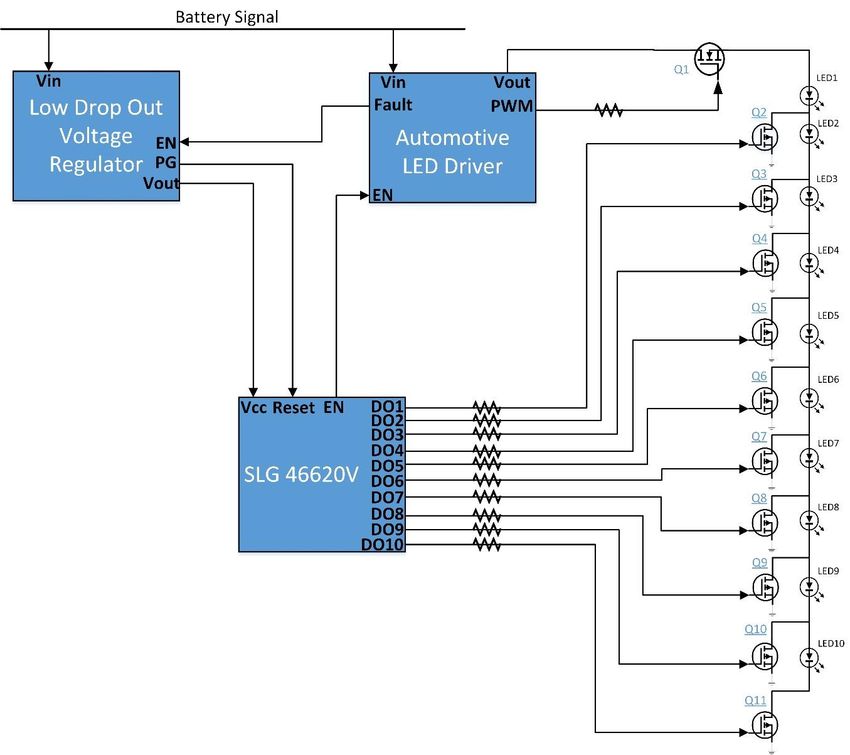
AN-CM-275
Automotive Turn Signal with Animation

Contents
Abstract ................................................................................................................................................ 1
Contents ............................................................................................................................................... 2
Figures .................................................................................................................................................. 2
Tables ................................................................................................................................................... 2
1    Terms and Definitions ................................................................................................................... 3
2    References ..................................................................................................................................... 3
3    Introduction.................................................................................................................................... 4
4    Industry Value ................................................................................................................................ 4
     4.1 Cost Comparison .................................................................................................................. 4
5    System Design ............................................................................................................................... 5
6    GreenPak Design ........................................................................................................................... 6
     6.1 Design Example 1 ............................................................................................................... 10
     6.2 Design Example 2 ............................................................................................................... 12
     6.3 Design Example 3 ............................................................................................................... 14
7    Experimentation Results ............................................................................................................ 16
8    Conclusion ................................................................................................................................... 18
Revision History ................................................................................................................................ 19

Figures
Figure 1: Scheme 1 with Single Channel Driver ................................................................................... 5
Figure 2: Scheme 2 with Multiple Channel Driver ................................................................................. 6
Figure 3: Example 1 Pattern .................................................................................................................. 7
Figure 4: Example 2 Pattern .................................................................................................................. 7
Figure 5: Example 3 Pattern .................................................................................................................. 7
Figure 6: 4-bit Moore State Machine ..................................................................................................... 9
Figure 7: Example 1 GreenPAK Design Matrix-0 ................................................................................ 11
Figure 8: Example 1 GreenPAK Design Matrix-1 ................................................................................ 12
Figure 9: Example 2 GreenPAK Design Matrix-0 ................................................................................ 13
Figure 10: Example 2 GreenPAK Design Matrix-1 .............................................................................. 14
Figure 11: Example 3 GreenPAK Design Matrix-0 .............................................................................. 15
Figure 12: Example 3 GreenPAK Design Matrix-1 .............................................................................. 16
Figure 13: Temporal Behavior of Output Signals for Example 1 with IND=1 ...................................... 17
Figure 14: Temporal Behavior of Output Signals for Example 2 with IND=1 ...................................... 17
Figure 15: Temporal Behavior of Output Signals for Example 3 with IND=1 ...................................... 18

Tables
Table 1: Cost Comparison ..................................................................................................................... 4
Table 2: 16 State Moore Machine for 3 Example Pattern Designs ....................................................... 8

Application Note                                                  Revision 1.0                                                         11-Sep-2018

                                                                        2 of 20                                          © 2018 Dialog Semiconductor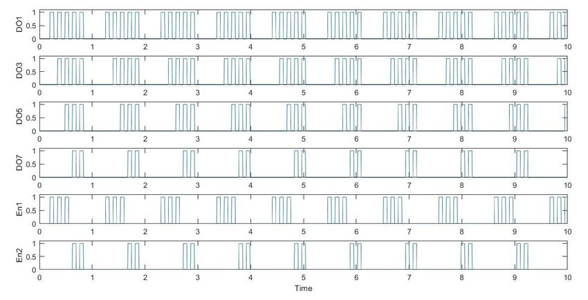
AN-CM-275
Automotive Turn Signal with Animation

1      Terms and Definitions
ASM                Asynchronous state machine
DFF                D flip flop
DO                 Digital output
EN                 Enable signal
FSM                Finite state machine
IC                 Integrated circuit
IC                 Integrated circuit
IND                Indicator signal
LDO                Low-drop out
LED                Light emitting diode
LUT                Look up table
MCU                Microcontroller unit
MOSFET             Metal-oxide semiconductor field-effect transistor
PCB                Printed circuit board
PG                 Power good
QFN                Quad flat no-lead
TSSOP              Thin shrink small outline package

2      References
For related documents and software, please visit:
https://www.dialog-semiconductor.com/products/greenpak.
Download our free GreenPAK™ Designer software [1] to open the .gp files [2] and view the proposed
circuit design. Use the GreenPAK development tools [3] to freeze the design into your own
customized IC in a matter of minutes. Dialog Semiconductor provides a complete library of
application notes [4] featuring design examples as well as explanations of features and blocks within
the Dialog IC.
[1]   GreenPAK Designer Software, Software Download and User Guide, Dialog Semiconductor
[2]   AN-CM-xxx Automotive Turn Signal with Animation.gp, GreenPAK Design File, Dialog
      Semiconductor
[3]   GreenPAK Development Tools, GreenPAK Development Tools Webpage, Dialog
      Semiconductor
[4]   GreenPAK Application Notes, GreenPAK Application Notes Webpage, Dialog Semiconductor
[5]   SLG 46620, Datasheet, Dialog Semiconductor.

Application Note                           Revision 1.0                                  11-Sep-2018

                                               3 of 20                        © 2018 Dialog Semiconductor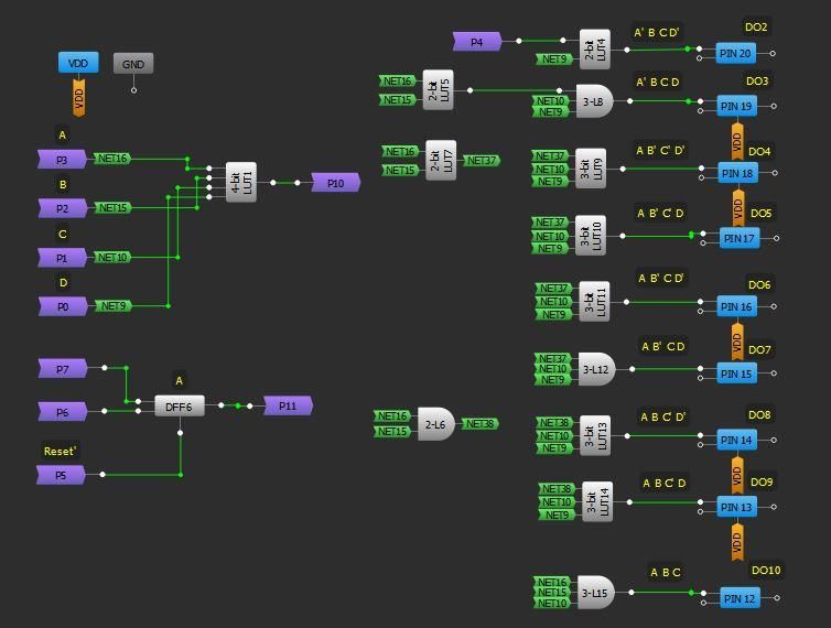
AN-CM-275
Automotive Turn Signal with Animation

3       Introduction
Recently, animated indicator front and rear LED patterns have become a norm in the automotive
industry. These running LED patterns often represent a trademark of the automotive manufacturers
and are used for visual aesthetics as well. The animations can be of different running patterns and
can be implemented without any MCU using several discrete ICs.
The major requirements of such designs are: reproducible performance during normal operation, an
option to force all LEDs on, low power consumption, disabling the used LDO regulator during a fault,
loading the LED driver before enabling it etc. Additionally, the requirements can vary from one
manufacturer to another. Moreover, usually in automotive applications, TSSOP ICs are usually
preferred due to their robustness as compared to QFN ICs since these are known to be prone to
solder fatigue issues especially in harsh environments. Fortunately for this automotive application,
Dialog Semiconductor provides a suitable GreenPAK IC, namely SLG46620, available in both QFN
and TSSOP packages.
All of the requirements for the animated indicator LED patterns are currently met in the automotive
industry using discrete ICs. However, the level of flexibility provided by GreenPAK IC is unmatched
and can easily cater to varying requirements of several manufacturers without any change in
hardware design. Moreover, significant PCB footprint reduction and cost savings are also achieved.
In this app note, a detailed description of achieving different animated indicator light patterns using
SLG46620 is presented.

4       Industry Value
The turn signal patterns shown in this app note are currently implemented in the automobile industry
using a number of discrete ICs to control the sequence of automotive indicator LED patterns. The
selected GreenPAK IC SLG46620 would replace at least the following components in the current
industrial design:
●     1 No. 555 Timer IC (e.g. TLC555QDRQ1)
●     1 No. Johnson Counter (e.g. CD4017)
●     2 No. D-Type Positive-Edge-Triggered Flip-Flop (e.g. 74HC74)
●     1 No. OR gate (e.g. CAHCT1G32)
●     Several passive components i.e. inductors, capacitors, resistors etc.

4.1      Cost Comparison
Table 1 provides the cost advantage obtained by using the selected Dialog GreenPAK IC, for the
indicator light sequential turn signal patterns, as compared to a current industrial solution.

Table 1: Cost Comparison
        IC Name              Quantity          Unit Price (Ref.                Price ($)
                                               Digi-key 23-05-
                                                  2018) ($)
     TLC555QDRQ1                 1                   0.86                        0.86
    SN74HC74QDRG4                2                   0.58                        1.16
          Q1
     CD74HC4017E                 1                   0.58                        0.58

Application Note                             Revision 1.0                                    11-Sep-2018

                                                 4 of 20                          © 2018 Dialog Semiconductor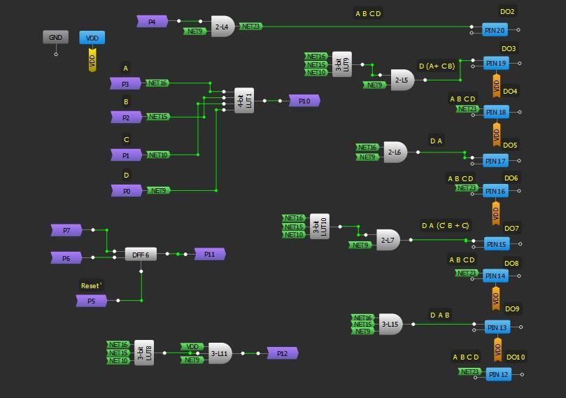
AN-CM-275
Automotive Turn Signal with Animation

         IC Name                Quantity            Unit Price (Ref.                     Price ($)
                                                    Digi-key 23-05-
                                                       2018) ($)
 CAHCT1G32QDBV                      1                      0.42                            0.42
      RQ1
                                                   Total Price:                            3.02
Note 1     The cost of other auxiliary components (i.e. several resistors, capacitors, inductors) is additional.
The selected GreenPAK IC SLG46620 would cost less than $0.50, so the total cost of the LED
control circuitry decreases significantly. In addition, significant comparative PCB footprint reduction is
also achieved.

5        System Design

                              Figure 1: Scheme 1 with Single Channel Driver

Application Note                                  Revision 1.0                                         11-Sep-2018

                                                       5 of 20                              © 2018 Dialog Semiconductor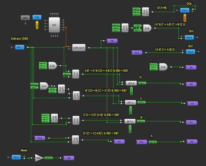
AN-CM-275
Automotive Turn Signal with Animation
Figure 1 shows the diagram of the first proposed scheme. The major components of the scheme
include a LDO voltage regulator, an automotive LED driver, an SLG46620, 11 logic-level MOSFETs
and 10 LEDs. The LDO voltage regulator ensures that appropriate voltage is provided to the IC and if
the battery voltage drops from a certain level the GreenPAK IC gets reset through the PG (Power
Good) pin. During any fault condition, detected by the LED driver, the LDO voltage regulator gets
disabled. The SLG46620 IC generates the digital signals to drive the indicator turn LEDs labelled 1-
10 through the MOSFETs. Moreover, the selected IC also produces the enable signal for the single
channel driver which in turn drives a MOSFET Q1 to load the driver running in constant current
mode.
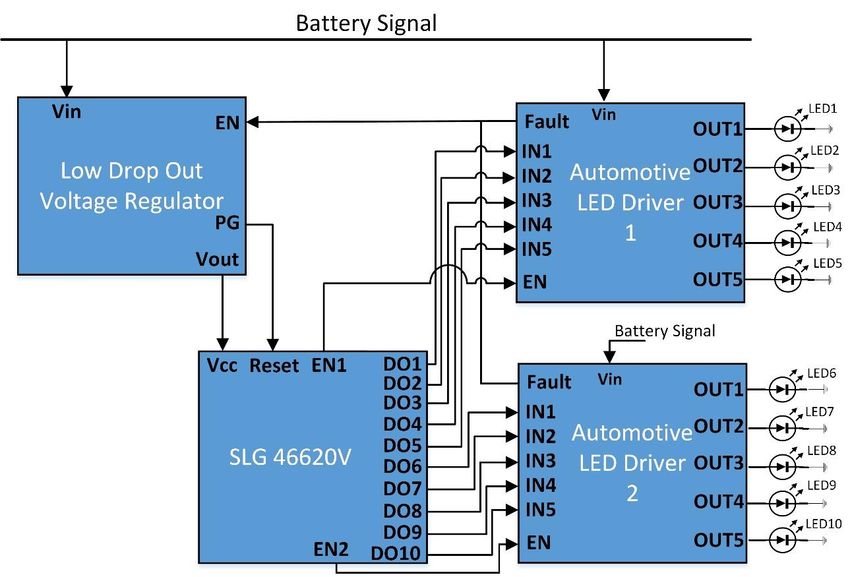
A variant of this scheme is also possible, where a multiple channel driver is employed, as shown in
Figure 2. In this option, the driving current of each channel reduces as compared to the single
channel driver.
Figure 2: Scheme 2 with Multiple Channel Driver
6 GreenPak Design
A suitable way to achieve the goal of flexible indicator LED patterns is to use a Finite State Machine
(FSM) concept. Dialog semiconductor provides several GreenPAK ICs that contain a built-in ASM
block. However, unfortunately all those GreenPAK ICs are available in QFN packages are not
recommended for harsh environments. So SLG46620 is chosen which is available in both QFN and
TSSOP packaging.
Three examples are presented for three different LED animations. For the first two examples, we
consider a single channel driver as shown in Figure 1. For the third example, we assume that
multiple channel drivers are available, as shown in Figure 2, and each channel is used to drive a
separate LED. Other patterns can also be obtained using the same concept.
In the first example design, LEDs from 1-10 are sequentially turned on one after the other once a
certain programmable time period expires as shown in Figure 3.
Application Note Revision 1.0 11-Sep-2018
6 of 20 © 2018 Dialog Semiconductor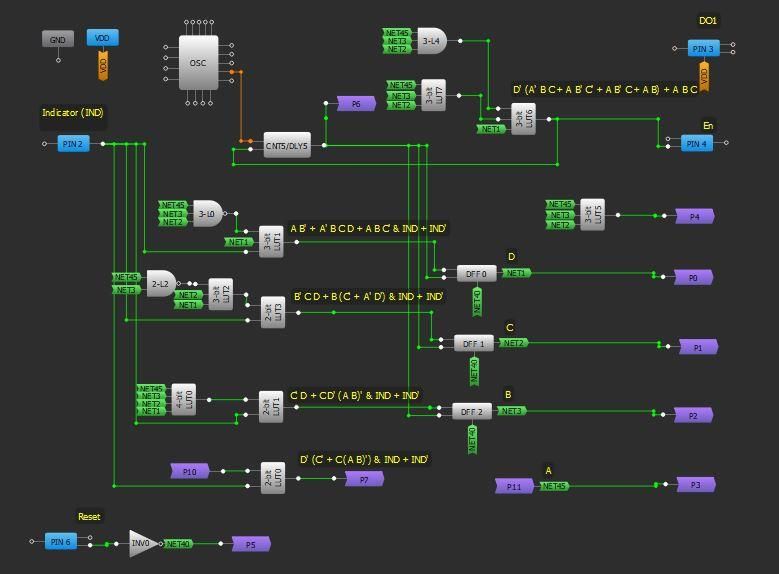
AN-CM-275
Automotive Turn Signal with Animation

                                    Figure 3: Example 1 Pattern

In the second example design, 2 LEDs are sequentially added in the pattern as shown in Figure 4.

                                    Figure 4: Example 2 Pattern

Figure 5 depicts how alternate LEDs are sequentially added in the pattern in the third proposed
design.

                                    Figure 5: Example 3 Pattern

Since there is no built-in block of ASM available in SLG46620, a Finite State Moore Machine is
developed using the available blocks namely counter, DFFs and LUTs. A 16 state Moore Machine is
developed using Table 2 for the three examples. In Table 2, all the bits of the present state and the
next state are given. Moreover, the bits for all the output signals are also provided. From Table 2 the
equations of the next state and all the outputs are evaluated in terms of the present state bits.

Application Note                            Revision 1.0                                    11-Sep-2018

                                                7 of 20                          © 2018 Dialog Semiconductor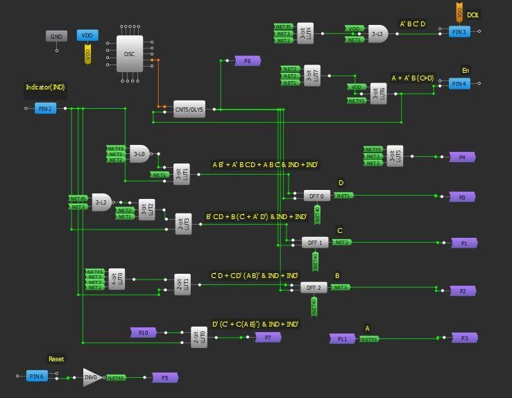
AN-CM-275
Automotive Turn Signal with Animation

Table 2: 16 State Moore Machine for 3 Example Pattern Designs
 Indicator   Present   Next      En       LEDs On         En       LEDs      En1          En2         LEDs
   Signal     State    State   (Ex. 1)     (Ex. 1)      (Ex. 2)     On      (Ex. 3)      (Ex. 3)       On
             ABCD      ABCD                                       (Ex. 2)                             (Ex. 3)
    0         0000     1111      0            0           0          0         0            0             0

    0         0001     1111      0            0           0          0         0            0             0

    0         0010     1111      0            0           0          0         0            0             0

    0         0011     1111      0            0           0          0         0            0             0

    0         0100     1111      0            0           0          0         0            0             0

    0         0101     1111      1            1           0          0         1            0             1

    0         0110     1111      1           1+2          1         1+2        0            0             0

    0         0111     1111      1          1+2+3         0          0         1            0             1+3

    0         1000     1111      1         1+2+3+4        1       1+2+3+4      0            0             0

    0         1001     1111      1       1+2+3+4+5        0          0         1            0         1+3+5

    0         1010     1111      1       1+2+3+4+5+       1       1+2+3+4      0            0             0
                                              6                     +5+6
    0         1011     1111      1       1+2+3+4+5+       0          0         0            1        1+3+5+7
                                             6+7
    0         1100     1111      1       1+2+3+4+5+       1       1+2+3+4      0            0             0
                                            6+7+8                 +5+6+7+
                                                                     8
    0         1101     1111      1       1+2+3+4+5+       0          0         0            1        1+3+5+7
                                           6+7+8+9                                                     +9

    0         1110     1111      1       1+2+3+4+5+       1       1+2+3+4      0            0             0
                                         6+7+8+9+10               +5+6+7+
                                                                   8+9+10
    1         0000     0001      0            0           0          0         0            0             0

    1         0001     0010      0            0           0          0         0            0             0

    1         0010     0011      0            0           0          0         0            0             0

    1         0011     0100      0            0           0          0         0            0             0

    1         0100     0101      0            0           0          0         0            0             0

    1         0101     0110      1            1           0          0         1            0             1

    1         0110     0111      1           1+2          1         1+2        0            0             0

    1         0111     1000      1          1+2+3         0          0         1            0             1+3

    1         1000     1001      1         1+2+3+4        1       1+2+3+4      0            0             0

Application Note                         Revision 1.0                                  11-Sep-2018

                                            8 of 20                         © 2018 Dialog Semiconductor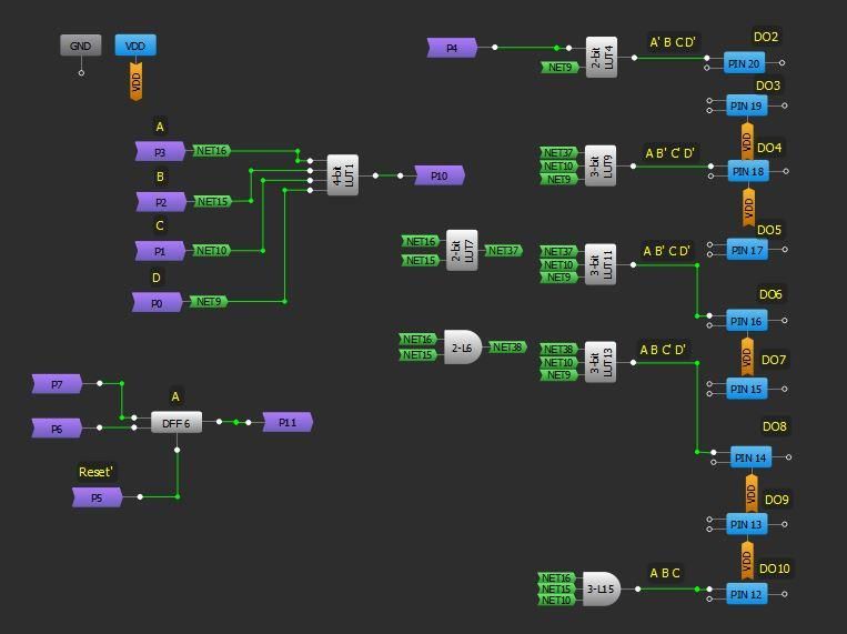
AN-CM-275
Automotive Turn Signal with Animation

 Indicator   Present     Next        En       LEDs On            En       LEDs      En1          En2         LEDs
   Signal     State      State     (Ex. 1)     (Ex. 1)         (Ex. 2)     On      (Ex. 3)      (Ex. 3)       On
             ABCD        ABCD                                            (Ex. 2)                             (Ex. 3)
     1        1001       1010         1      1+2+3+4+5           0          0         1            0         1+3+5

     1        1010       1011         1      1+2+3+4+5+          1       1+2+3+4      0            0             0
                                                  6                        +5+6
     1        1011       1100         1      1+2+3+4+5+          0          0         0            1        1+3+5+7
                                                 6+7
     1        1100       1101         1      1+2+3+4+5+          1       1+2+3+4      0            0             0
                                                6+7+8                    +5+6+7+
                                                                            8
     1        1101       1110         1      1+2+3+4+5+          0          0         0            1        1+3+5+7
                                               6+7+8+9                                                        +9

     1        1110       0000         1      1+2+3+4+5+          1       1+2+3+4      0            0             0
                                             6+7+8+9+10                  +5+6+7+
                                                                          8+9+10
     1        1111       0000         1      1+2+3+4+5+          1       1+2+3+4      1            1        1+2+3+4
                                             6+7+8+9+10                  +5+6+7+                            +5+6+7+
                                                                          8+9+10                             8+9+10
Note 2   The first three columns are common for each example

                                 Figure 6: 4-bit Moore State Machine

At the core of the development of 4-bit Moore Machine are 4 DFF blocks. Each DFF block
functionally represents one bit of the four bits: ABCD. When the indicator signal is high
Application Note                             Revision 1.0                                     11-Sep-2018

                                                9 of 20                            © 2018 Dialog Semiconductor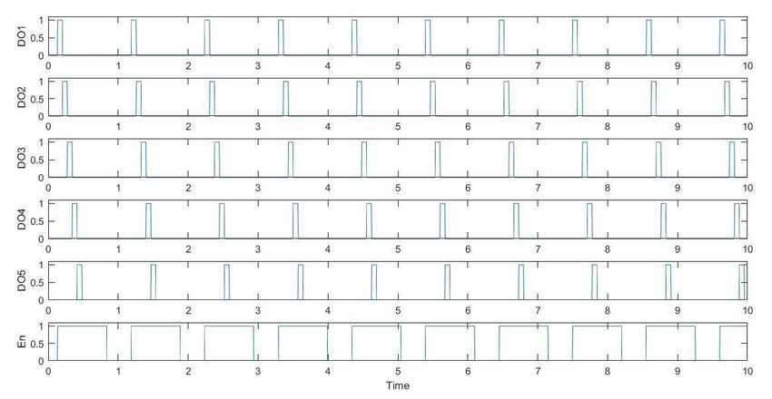
AN-CM-275
Automotive Turn Signal with Animation

(corresponding to an on indicator switch), a transition from one state to the next is required at each
clock pulse, thus generating different LED patterns as a result. On the other hand, when the indicator
signal is low, a stationary pattern, having all the LEDs on in each design example is the goal.
Figure 3 shows the functionality of the developed 4-bit (ABCD) Moore Machine for each example.
The basic idea of the development of such FSM is to represent each bit of the next state, the enable
signal and each output pin signal (assigned for the LEDs) in terms of the present state. This is where
the LUTs contribute. All the 4 bits of present state are fed to different LUTs to basically achieve the
required signal in the next state at the edge of a clock pulse. For the clock pulse, a counter is
configured to provide a pulse train with a suitable period.
For each example, each bit of the next state is evaluated in terms of the present state using the
following equations derived from K-Maps:
A = D' (C' + C (A B)') & IND + IND'
B = C' D + C D' (A B)' & IND + IND'
C = B' C D + B (C' + A' D') & IND + IND'
D = A B' + A' B C D + A B C' & IND + IND'
where IND represents the indicator signal.
Further details of each of the three examples are given below.

6.1    Design Example 1
The equations of the enable signal and the LED driving signals for the 1st example, with each LED
turning on sequentially using the scheme in Figure 1, are as shown below.
En = A + A' B (C+D)
DO1 = A' B C' D         DO2 = A' B C D'           DO3 = A' B C D         DO4 = A B' C' D'
DO5 = A B' C' D         DO6 = A B' C D'           DO7 = A B' C D         DO8 = A B C' D'
DO9 = A B C' D           DO10 = A B C

Application Note                             Revision 1.0                                  11-Sep-2018

                                                10 of 20                        © 2018 Dialog Semiconductor
AN-CM-275
Automotive Turn Signal with Animation
Figure 7: Example 1 GreenPAK Design Matrix-0
In Figure 7, the Matrix-0 GreenPAK design of Example 1 is shown. 4 DFFs are used to develop the
4-bit Moore Machine. DFFs with reset option (3 from Matrix-0 and 1 from Matrix-1) are selected so
that the Moore Machine can be reset conveniently. A counter, with a suitable time period of 72 mS, is
configured to change the state of the Machine after each period. LUTs with appropriate
configurations are used to derive functions for the DFFs inputs, Driver Enable Signal (En), and the
output pins: DO1-DO10.
Application Note Revision 1.0 11-Sep-2018
11 of 20 © 2018 Dialog SemiconductorAN-CM-275
Automotive Turn Signal with Animation
Figure 8: Example 1 GreenPAK Design Matrix-1
In Matrix shown in Figure 8, the rest of the GreenPAK resources are utilized to complete the design
using the methodology described earlier. The figures are appropriately labeled for clarity.
6.2 Design Example 2
The equations of the enable signal and the LED driving signals for the 2nd example, with two LEDs
adding in the sequential pattern using the scheme in Figure 1, are as shown below.
En = D' (A' B C + A B' C' + A B' C + A B) + A B C
DO1 = 0 DO2 = A' B C D' DO3 = 0 DO4 = A B' C' D'
DO5 = 0 DO6 = A B' C D' DO7 = 0 DO8 = A B C' D'
DO9 = 0 DO10 = A B C
In Figure 9 and Figure 10, the Matrix-0 & 1 GreenPAK designs of Example 2 are presented. The
basic design is similar to the Example 1 design. The major differences, in comparison, are in the
Driver Enable (En) function and no connections of DO1, DO3, DO5, DO7 and DO10, which are
pulled down in this design.
Application Note Revision 1.0 11-Sep-2018
12 of 20 © 2018 Dialog SemiconductorAN-CM-275
Automotive Turn Signal with Animation
Figure 9: Example 2 GreenPAK Design Matrix-0
Application Note Revision 1.0 11-Sep-2018
13 of 20 © 2018 Dialog SemiconductorAN-CM-275
Automotive Turn Signal with Animation
Figure 10: Example 2 GreenPAK Design Matrix-1
6.3 Design Example 3
The equations of the enable signal and the LED driving signals for the 3rd example, generating
alternate LED sequential addition pattern using the scheme in Figure 2, are given below.
En1 = (A' B C' + A B' C' + B C) D
En2 = (A B' C + A B) D
DO1 = D (A+B) DO2 = A B C D DO3 = D (A+ C B) DO4 = A B C D
DO5 = D A DO6 = A B C D DO7 = D A (C' B + C) DO8 = A B C D
DO9 = D A B DO10 = A B C D
In Figure 11 and Figure 12, the Matrix-0 & 1 GreenPAK designs of Example 3 are presented. In this
design, there a two separate Driver Enable Signals (En1 & En2) for Driver 1 & 2. Moreover, the
output pins are connected to the outputs of appropriately configured LUTs.
This concludes the GreenPAK design part of Example 1, Example 2 and Example 3.
Application Note Revision 1.0 11-Sep-2018
14 of 20 © 2018 Dialog SemiconductorAN-CM-275
Automotive Turn Signal with Animation
Figure 11: Example 3 GreenPAK Design Matrix-0
Application Note Revision 1.0 11-Sep-2018
15 of 20 © 2018 Dialog SemiconductorAN-CM-275
Automotive Turn Signal with Animation
Figure 12: Example 3 GreenPAK Design Matrix-1
7 Experimentation Results
A convenient way to test the designs of Example 1, Example 2 and Example 3 is experimentation
and visual inspection. The temporal behavior of each scheme is analyzed using a logic analyzer and
the results are presented in this section.
Figure 13 shows the temporal behavior of different output signals for Example 1 whenever the
indicator is turned on (IND=1). It can be observed that the signals for the output pins DO1-DO5
sequentially turn on after the other after a set time period expires in accordance with Table 2. The
pattern of the signals provided to the pins DO6-DO10 is also similar. The Driver Enable (En) signal
turns on when any of the signals DO1-DO10 is turned on and otherwise it is off. During the
animation, whenever the indicator signal goes low (IND=0), the En and DO10 signals turn on and
remain logical high. In short, the results meet the requirements and validate the theoretical proposals
for Example 1.
In Figure 14, the timing diagram of different output signals for Example 2, with the indicator signal
turned on (IND=1), is depicted. It is observed that the signals for the output pins DO1-DO5 are turned
on alternately in a sequence after some time period in agreement with Table 2. The pins DO1, DO3
and DO5 remain low, whereas the signals for the DO2 and DO4 alternately turn on sequentially. The
same patterns for DO6-DO10 are also observed (not shown in the figure due to limited number of
analyzer inputs). Whenever any of the signals DO1-DO10 is on, the Driver Enable (En) signal also
turns on which otherwise remains off. Throughout the animation, whenever the indicator signal goes
low (IND=0), the En and DO10 signals turn on and remain logical high. The results meet the
requirements and the theoretical ideas for Example 2 exactly.
Application Note Revision 1.0 11-Sep-2018
16 of 20 © 2018 Dialog SemiconductorAN-CM-275
Automotive Turn Signal with Animation
Figure 13: Temporal Behavior of Output Signals for Example 1 with IND=1
Figure 14: Temporal Behavior of Output Signals for Example 2 with IND=1
Application Note Revision 1.0 11-Sep-2018
17 of 20 © 2018 Dialog SemiconductorAN-CM-275
Automotive Turn Signal with Animation
Figure 15: Temporal Behavior of Output Signals for Example 3 with IND=1
Figure 15 shows, the timing diagram of different output signals for Example 3, with the indicator
signal turned on (IND=1). It can be observed that the signals for the output pins DO1-DO7 turn on as
shown in Table 2. Moreover, pin DO9 signal also behaves according to Table 2 (not shown on
figure). Pins DO2, DO4, DO6, DO8, DO10 remain low. The En1 turns logical high whenever a signal
from DO1, DO3 and DO5 is on and En2 turns logical high whenever a signal from DO7 and DO9
goes high. During the entire animation, whenever the indicator signal is goes low (IND=0), all the
output signals: En1, En2 and DO1-DO10 turn on and remain logical high. Therefore, it can be
concluded that the results fulfill the requirements and the theoretical proposals for Example 3.
8 Conclusion
A detailed description of various automotive turn signal schemes with animation has been presented.
A suitable Dialog IC SLG46620 was chosen for this application since it is also available in TSSOP
package which is advisable for the harsh environment industrial applications. Two major schemes,
using single and multiple channel automotive drivers, are presented to develop flexible sequential
LED animation models. Appropriate Finite State Moore Machine models are developed to generate
the desired animations. For validation of the developed model, convenient experimentation has been
carried out. It is established that the functionality of the developed models agrees with the theoretical
design.
Application Note Revision 1.0 11-Sep-2018
18 of 20 © 2018 Dialog SemiconductorAN-CM-275
Automotive Turn Signal with Animation
Revision History
Revision Date Description
1.0 11-Sep-2018 Initial Version
Application Note Revision 1.0 11-Sep-2018
19 of 20 © 2018 Dialog SemiconductorAN-CM-275
Automotive Turn Signal with Animation
Status Definitions
Status Definition
The content of this document is under review and subject to formal approval, which may result in modifications or
DRAFT
additions.
APPROVED
The content of this document has been approved for publication.
or unmarked
Disclaimer
Information in this document is believed to be accurate and reliable. However, Dialog Semiconductor does not give any representations or
warranties, expressed or implied, as to the accuracy or completeness of such information. Dialog Semiconductor furthermore takes no
responsibility whatsoever for the content in this document if provided by any information source outside of Dialog Semiconductor.
Dialog Semiconductor reserves the right to change without notice the information published in this document, including without limitation the
specification and the design of the related semiconductor products, software and applications.
Applications, software, and semiconductor products described in this document are for illustrative purposes only. Dialog Semiconductor makes
no representation or warranty that such applications, software and semiconductor products will be suitable for the specified use without further
testing or modification. Unless otherwise agreed in writing, such testing or modification is the sole responsibility of the customer and Dialog
Semiconductor excludes all liability in this respect.
Customer notes that nothing in this document may be construed as a license for customer to use the Dialog Semiconductor products, software
and applications referred to in this document. Such license must be separately sought by customer with Dialog Semiconductor.
All use of Dialog Semiconductor products, software and applications referred to in this document are subject to Dialog Semiconductor’s Standard
Terms and Conditions of Sale, available on the company website (www.dialog-semiconductor.com) unless otherwise stated.
Dialog and the Dialog logo are trademarks of Dialog Semiconductor plc or its subsidiaries. All other product or service names are the property of
their respective owners.
© 2018 Dialog Semiconductor. All rights reserved.
Contacting Dialog Semiconductor
United Kingdom (Headquarters) North America Hong Kong China (Shenzhen)
Dialog Semiconductor (UK) LTD Dialog Semiconductor Inc. Dialog Semiconductor Hong Kong Dialog Semiconductor China
Phone: +44 1793 757700 Phone: +1 408 845 8500 Phone: +852 2607 4271 Phone: +86 755 2981 3669
Germany Japan Korea China (Shanghai)
Dialog Semiconductor GmbH Dialog Semiconductor K. K. Dialog Semiconductor Korea Dialog Semiconductor China
Phone: +49 7021 805-0 Phone: +81 3 5769 5100 Phone: +82 2 3469 8200 Phone: +86 21 5424 9058
The Netherlands Taiwan
Dialog Semiconductor B.V. Dialog Semiconductor Taiwan
Phone: +31 73 640 8822 Phone: +886 281 786 222
Email: Web site:
enquiry@diasemi.com www.dialog-semiconductor.com
Application Note Revision 1.0 11-Sep-2018
20 of 20 © 2018 Dialog SemiconductorYou can also read