GDFLIB User's Guide ARM Cortex M7F - Document Number: CM7FGDFLIBUG Rev. 3, 05/2020 - NXP Semiconductors
←
→
Page content transcription
If your browser does not render page correctly, please read the page content below
GDFLIB User's Guide
             ARM® Cortex® M7F

     Document Number: CM7FGDFLIBUG
                       Rev. 3, 05/2020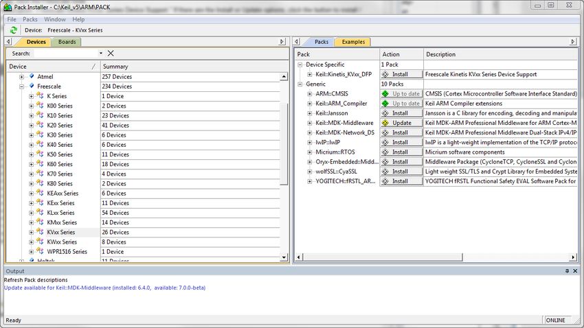
GDFLIB User's Guide, Rev. 3, 05/2020
2                                          NXP Semiconductors
Contents
Section number                                                                         Title                                                                                     Page

                                                                                  Chapter 1
                                                                                   Library
1.1   Introduction.................................................................................................................................................................... 5

1.2   Library integration into project (MCUXpresso IDE) ....................................................................................................8

1.3   Library integration into project (Kinetis Design Studio) .............................................................................................. 16

1.4   Library integration into project (Keil µVision) ............................................................................................................. 24

1.5   Library integration into project (IAR Embedded Workbench) ..................................................................................... 32

                                                                           Chapter 2
                                                                       Algorithms in detail
2.1   GDFLIB_FilterExp.........................................................................................................................................................41

2.2   GDFLIB_FilterIIR1........................................................................................................................................................45

2.3   GDFLIB_FilterIIR2........................................................................................................................................................50

2.4   GDFLIB_FilterIIR3........................................................................................................................................................57

2.5   GDFLIB_FilterIIR4........................................................................................................................................................63

2.6   GDFLIB_FilterMA.........................................................................................................................................................70

                                                          GDFLIB User's Guide, Rev. 3, 05/2020
NXP Semiconductors                                                                                                                                                                         3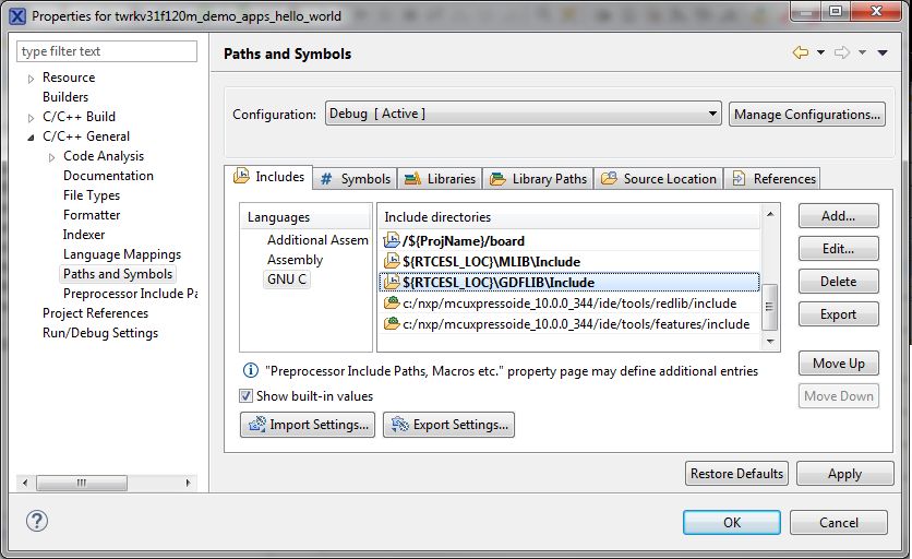
GDFLIB User's Guide, Rev. 3, 05/2020
4                                          NXP Semiconductors
Chapter 1
Library

1.1 Introduction

1.1.1 Overview
This user's guide describes the General Digital Filters Library (GDFLIB) for the family
of ARM Cortex M7F core-based microcontrollers. This library contains optimized
functions.

1.1.2 Data types
GDFLIB supports several data types: (un)signed integer, fractional, and accumulator, and
floating point. The integer data types are useful for general-purpose computation; they
are familiar to the MPU and MCU programmers. The fractional data types enable
powerful numeric and digital-signal-processing algorithms to be implemented. The
accumulator data type is a combination of both; that means it has the integer and
fractional portions.The floating-point data types are capable of storing real numbers in
wide dynamic ranges. The type is represented by binary digits and an exponent. The
exponent allows scaling the numbers from extremely small to extremely big numbers.
Because the exponent takes part of the type, the overall resolution of the number is
reduced when compared to the fixed-point type of the same size.
The following list shows the integer types defined in the libraries:
  • Unsigned 16-bit integer — with the minimum resolution of 1
  • Signed 16-bit integer — with the minimum resolution of 1
  • Signed 32-bit integer — with the minimum resolution
    of 1

                              GDFLIB User's Guide, Rev. 3, 05/2020
NXP Semiconductors                                                                        5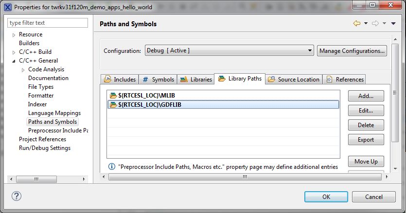
Introduction

The following list shows the fractional types defined in the libraries:
    • Fixed-point 16-bit fractional — with the minimum resolution of 2-15
    • Fixed-point 32-bit fractional — with the minimum resolution of 2-31
The following list shows the accumulator types defined in the libraries:
    • Fixed-point 16-bit accumulator — with the minimum
      resolution of 2-7
    • Fixed-point 32-bit accumulator — with the minimum
      resolution of 2-15
The following list shows the floating-point types defined in the libraries:
    • Floating point 32-bit single precision — with the
      minimum resolution of 2-23

1.1.3 API definition
GDFLIB uses the types mentioned in the previous section. To enable simple usage of the
algorithms, their names use set prefixes and postfixes to distinguish the functions'
versions. See the following example:

f32Result = MLIB_Mac_F32lss(f32Accum, f16Mult1, f16Mult2);

where the function is compiled from four parts:
    •   MLIB—this is the library prefix
    •   Mac—the function name—Multiply-Accumulate
    •   F32—the function output type
    •   lss—the types of the function inputs; if all the inputs have the same type as the
        output, the inputs are not marked
The input and output types are described in the following table:
                                  Table 1-1. Input/output types
                                 Type           Output           Input
                                frac16_t         F16              s
                                frac32_t         F32               l
                                acc32_t          A32              a
                                float_t          FLT              f

                                 GDFLIB User's Guide, Rev. 3, 05/2020
6                                                                               NXP Semiconductors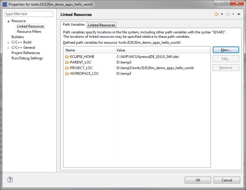
Chapter 1 Library

1.1.4 Supported compilers
GDFLIB for the ARM Cortex M7F core is written in . The library is built and tested
using the following compilers:
  • Kinetis Design Studio
  • MCUXpresso IDE
  • IAR Embedded Workbench
  • Keil µVision
For the MCUXpresso IDE, the library is delivered in the gdflib.a file.
For the Kinetis Design Studio, the library is delivered in the gdflib.a file.
For the IAR Embedded Workbench, the library is delivered in the gdflib.a file.
For the Keil µVision, the library is delivered in the gdflib.lib file.
The interfaces to the algorithms included in this library are combined into a single public
interface include file, gdflib.h. This is done to lower the number of files required to be
included in your application.

1.1.5 Library configuration
GDFLIB for the ARM Cortex M7F core is written in . Some functions from this library
are inline type, which are compiled together with project using this library. The
optimization level for inline function is usually defined by the specific compiler setting. It
can cause an issue especially when high optimization level is set. Therefore the
optimization level for all inline assembly written functions is defined by compiler
pragmas using macros. The configuration header file RTCESL_cfg.h is located in:
specific library folder\MLIB\Include. The optimization level can be changed by
modifying the macro value for specific compiler. In case of any change the library
functionality is not guaranteed.

1.1.6 Special issues
 1. The equations describing the algorithms are symbolic. If there is positive 1, the
    number is the closest number to 1 that the resolution of the used fractional type
    allows. If there are maximum or minimum values mentioned, check the range
    allowed by the type of the particular function version.
 2. The library functions that round the result (the API contains Rnd) round to nearest
    (half up).

                               GDFLIB User's Guide, Rev. 3, 05/2020
NXP Semiconductors                                                                             7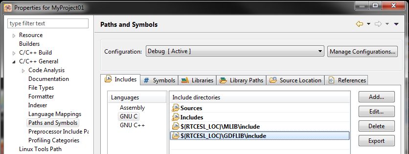
Library integration into project (MCUXpresso IDE)

1.2 Library integration into project (MCUXpresso IDE)
This section provides a step-by-step guide on how to quickly and easily include GDFLIB
into any MCUXpresso SDK example or demo application projects using MCUXpresso
IDE. This example uses the default installation path (C:\NXP\RTCESL
\CM7F_RTCESL_4.5_MCUX). If you have a different installation path, use that path
instead.

1.2.1 High-speed functions execution suppport
Some RT (or other) platforms contain high-speed functions execution support by
relocating all functions from the default Flash memory location to the RAM location for
much faster code access. The feature is important especially for devices with a slow Flash
interface. This section shows how to turn the RAM optimization feature support on and
off.
    1. In the MCUXpresso SDK project name node or on the left-hand side, click Properties
       or select Project > Properties from the menu. A project properties dialog appears.
    2. Expand the C/C++ Build node and select Settings. See .
    3. On the right-hand side, under the MCU C Compiler node, click the Preprocessor
       node. See .

                                     GDFLIB User's Guide, Rev. 3, 05/2020
8                                                                           NXP Semiconductors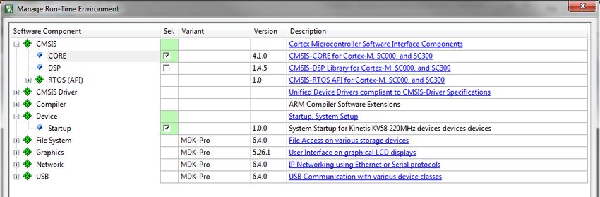
Chapter 1 Library

                               Figure 1-1. Defined symbols
 4. On the right-hand side of the dialog, click the Add... icon located next to the Defined
    symbols (-D) title.
 5. In the dialog that appears (see ), type the following:
      • RAM_OPTIM_HIGH—to turn the RAM optimization feature support on
      • RAM_OPTIM_MEDIUM—to turn the RAM optimization feature support on
      • RAM_OPTIM_LOW—to turn the RAM optimization feature support on
     If any of these three defines is defined, all RTCEL functions are put into the RAM,
     regardless of which one is defined. The HIGH, MEDIUM, or LOW variants enable
     separating the Flash or RAM locations from the other user code or application
     functions. The RTCESL functions are always RAM-optimized if a variant is defined.

                              Figure 1-2. Symbol definition
 6. Click OK in the dialog.
 7. Click OK in the main dialog.

                             GDFLIB User's Guide, Rev. 3, 05/2020
NXP Semiconductors                                                                           9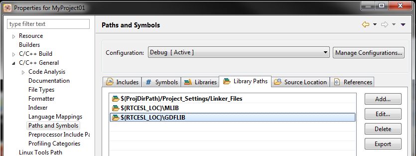
Library integration into project (MCUXpresso IDE)

The device reference manual shows how the__RAMFUNC(RAM) atribute works in connection
with your device.

1.2.2 Library path variable
To make the library integration easier, create a variable that holds the information about
the library path.
 1. Right-click the MCUXpresso SDK project name node in the left-hand part and click
    Properties, or select Project > Properties from the menu. A project properties dialog
    appears.
 2. Expand the Resource node and click Linked Resources. See Figure 1-3.

                                      Figure 1-3. Project properties
 3. Click the New… button in the right-hand side.

                                     GDFLIB User's Guide, Rev. 3, 05/2020
10                                                                          NXP Semiconductors
Chapter 1 Library
4. In the dialog that appears (see Figure 1-4), type this variable name into the Name
box: RTCESL_LOC.
5. Select the library parent folder by clicking Folder…, or just type the following path
into the Location box: C:\NXP\RTCESL\CM7F_RTCESL_4.5_MCUX. Click OK.
Figure 1-4. New variable
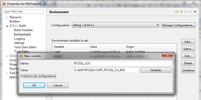
6. Create such variable for the environment. Expand the C/C++ Build node and click
Environment.
7. Click the Add… button in the right-hand side.
8. In the dialog that appears (see Figure 1-5), type this variable name into the Name
box: RTCESL_LOC.
9. Type the library parent folder path into the Value box: C:\NXP\RTCESL
\CM7F_RTCESL_4.5_MCUX.
10. Tick the Add to all configurations box to use this variable in all configurations. See
Figure 1-5.
11. Click OK.
12. In the previous dialog, click OK.
GDFLIB User's Guide, Rev. 3, 05/2020
NXP Semiconductors 11Library integration into project (MCUXpresso IDE)
Figure 1-5. Environment variable
1.2.3 Library folder addition
To use the library, add it into the Project tree dialog.
1. Right-click the MCUXpresso SDK project name node in the left-hand part and click
New > Folder, or select File > New > Folder from the menu. A dialog appears.
2. Click Advanced to show the advanced options.
3. To link the library source, select the Link to alternate location (Linked Folder)
option.
4. Click Variables..., select the RTCESL_LOC variable in the dialog, click OK, and/or
type the variable name into the box. See Figure 1-6.
5. Click Finish, and the library folder is linked in the project. See Figure 1-7.
GDFLIB User's Guide, Rev. 3, 05/2020
12 NXP SemiconductorsChapter 1 Library
Figure 1-6. Folder link
Figure 1-7. Projects libraries paths
1.2.4 Library path setup
GDFLIB requires MLIB to be included too. These steps show how to include all
dependent modules:
1. Right-click the MCUXpresso SDK project name node in the left-hand part and click
Properties, or select Project > Properties from the menu. The project properties
dialog appears.
2. Expand the C/C++ General node, and click Paths and Symbols.
3. In the right-hand dialog, select the Library Paths tab. See Figure 1-9.
4. Click the Add… button on the right, and a dialog appears.
GDFLIB User's Guide, Rev. 3, 05/2020
NXP Semiconductors 13Library integration into project (MCUXpresso IDE)
5. Look for the RTCESL_LOC variable by clicking Variables…, and then finish the
path in the box by adding the following (see Figure 1-8): ${RTCESL_LOC}\MLIB.
6. Click OK, and then click the Add… button.
7. Look for the RTCESL_LOC variable by clicking Variables…, and then finish the
path in the box by adding the following: ${RTCESL_LOC}\GDFLIB.
8. Click OK, you will see the paths added into the list. See Figure 1-9.
Figure 1-8. Library path inclusion
Figure 1-9. Library paths
9. After adding the library paths, add the library files. Click the Libraries tab. See
Figure 1-11.
10. Click the Add… button on the right, and a dialog appears.
11. Type the following into the File text box (see Figure 1-10): :mlib.a
12. Click OK, and then click the Add… button.
13. Type the following into the File text box: :gdflib.a
14. Click OK, and you will see the libraries added in the list. See Figure 1-11.
GDFLIB User's Guide, Rev. 3, 05/2020
14 NXP SemiconductorsChapter 1 Library
Figure 1-10. Library file inclusion
Figure 1-11. Libraries
15. In the right-hand dialog, select the Includes tab, and click GNU C in the Languages
list. See Figure 1-13.
16. Click the Add… button on the right, and a dialog appears. See Figure 1-12.
17. Look for the RTCESL_LOC variable by clicking Variables…, and then finish the
path in the box to be: ${RTCESL_LOC}\MLIB\Include
18. Click OK, and then click the Add… button.
19. Look for the RTCESL_LOC variable by clicking Variables…, and then finish the
path in the box to be: ${RTCESL_LOC}\GDFLIB\Include
20. Click OK, and you will see the paths added in the list. See Figure 1-13. Click OK.
Figure 1-12. Library include path addition
GDFLIB User's Guide, Rev. 3, 05/2020
NXP Semiconductors 15Library integration into project (Kinetis Design Studio)
Figure 1-13. Compiler setting
Type the #include syntax into the code where you want to call the library functions. In
the left-hand dialog, open the required .c file. After the file opens, include the following
lines into the #include section:
#include "mlib_FP.h"
#include "gdflib_FP.h"
When you click the Build icon (hammer), the project is compiled without errors.
1.3 Library integration into project (Kinetis Design Studio)
This section provides a step-by-step guide on how to quickly and easily include GDFLIB
into an empty project or any MCUXpresso SDK example or demo application projects
using Kinetis Design Studio. This example uses the default installation path (C:\NXP
\RTCESL\CM7F_RTCESL_4.5_KDS). If you have a different installation path, use that
path instead. If you want to use an existing MCUXpresso SDK project (for example the
hello_world project) see Library path variable. If not, continue with the next section.
GDFLIB User's Guide, Rev. 3, 05/2020
16 NXP SemiconductorsChapter 1 Library
1.3.1 High-speed functions execution suppport
Some RT (or other) platforms contain high-speed functions execution support by
relocating all functions from the default Flash memory location to the RAM location for
much faster code access. The feature is important especially for devices with a slow Flash
interface. This section shows how to turn the RAM optimization feature support on and
off.
1. Right-click the MyProject01 or MCUXpresso SDK project name node (or in the left-
hand side) and click Properties, or select Project > Properties from the menu. A
project properties dialog appears.
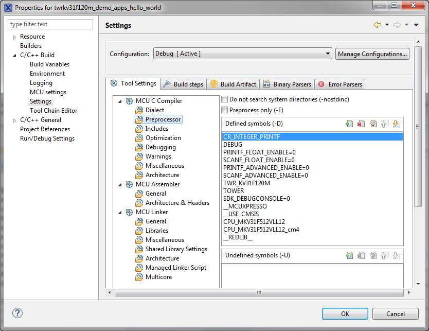
2. Expand the C/C++ Build node and select Settings. See .
3. On the right-hand side, under the Cross ARM C compiler node, click the
Preprocessor node. See .
Figure 1-14. Defined symbols
4. In the right-hand part of the dialog, click the Add... icon located next to the Defined
symbols (-D) title.
5. In the dialog that appears (see ), type the following:
• RAM_OPTIM_HIGH—to turn the RAM optimization feature support on
• RAM_OPTIM_MEDIUM—to turn the RAM optimization feature support on
• RAM_OPTIM_LOW—to turn the RAM optimization feature support on
GDFLIB User's Guide, Rev. 3, 05/2020
NXP Semiconductors 17Library integration into project (Kinetis Design Studio)
If any of these three defines is defined, all RTCEL functions are put into the RAM,
regardless of which one is defined. The HIGH, MEDIUM, or LOW variants enable
to separate the Flash or RAM locations from the other user code or application
functions. The RTCESL functions are always RAM optimized if a variant is defined.
Figure 1-15. Symbol definition
6. Click OK in the dialog.
7. Click OK in the main dialog.
The device reference manual shows how the __RAMFUNC(RAM) atribute works in connection
with your device.
1.3.2 Library path variable
To make the library integration easier, create a variable that will hold the information
about the library path.
1. Right-click the MyProject01 or MCUXpresso SDK project name node in the left-
hand part and click Properties, or select Project > Properties from the menu. A
project properties dialog appears.
2. Expand the Resource node and click Linked Resources. See Figure 1-16.
GDFLIB User's Guide, Rev. 3, 05/2020
18 NXP SemiconductorsChapter 1 Library
Figure 1-16. Project properties
3. Click the New… button in the right-hand side.
4. In the dialog that appears (see Figure 1-17), type this variable name into the Name
box: RTCESL_LOC.
5. Select the library parent folder by clicking Folder…, or just type the following path
into the Location box: C:\NXP\RTCESL\CM7F_RTCESL_4.5_KDS. Click OK.
Figure 1-17. New variable
GDFLIB User's Guide, Rev. 3, 05/2020
NXP Semiconductors 19Library integration into project (Kinetis Design Studio)
6. Create such variable for the environment. Expand the C/C++ Build node and click
Environment.
7. Click the Add… button in the right-hand side.
8. In the dialog that appears (see Figure 1-18), type this variable name into the Name
box: RTCESL_LOC.
9. Type the library parent folder path into the Value box: C:\NXP\RTCESL
\CM7F_RTCESL_4.5_KDS.
10. Tick the Add to all configurations box to use this variable in all configurations. See
Figure 1-18.
11. Click OK.
12. In the previous dialog, click OK.
Figure 1-18. Environment variable
1.3.3 Library folder addition
To use the library, add it into the Project tree dialog.
1. Right-click the MyProject01 or MCUXpresso SDK project name node in the left-
hand part and click New > Folder, or select File > New > Folder from the menu. A
dialog appears.
2. Click Advanced to show the advanced options.
3. To link the library source, select the option Link to alternate location (Linked
Folder).
4. Click Variables..., select the RTCESL_LOC variable in the dialog, click OK, and/or
type the variable name into the box. See Figure 1-19.
GDFLIB User's Guide, Rev. 3, 05/2020
20 NXP SemiconductorsChapter 1 Library
5. Click Finish, and you will see the library folder linked in the project. See Figure
1-20.
Figure 1-19. Folder link
Figure 1-20. Projects libraries paths
1.3.4 Library path setup
GDFLIB requires MLIB to be included too. These steps show how to include all
dependent modules:
1. Right-click the MyProject01 or MCUXpresso SDK project name node in the left-
hand part and click Properties, or select Project > Properties from the menu. A
project properties dialog appears.
2. Expand the C/C++ General node, and click Paths and Symbols.
3. In the right-hand dialog, select the Library Paths tab. See Figure 1-22.
GDFLIB User's Guide, Rev. 3, 05/2020
NXP Semiconductors 21Library integration into project (Kinetis Design Studio)
4. Click the Add… button on the right, and a dialog appears.
5. Look for the RTCESL_LOC variable by clicking Variables…, and then finish the
path in the box by adding the following (see Figure 1-21): ${RTCESL_LOC}\MLIB.
6. Click OK, and then click the Add… button.
7. Look for the RTCESL_LOC variable by clicking Variables…, and then finish the
path in the box by adding the following: ${RTCESL_LOC}\GDFLIB.
8. Click OK, and the paths will be visible in the list. See Figure 1-22.
Figure 1-21. Library path inclusion
Figure 1-22. Library paths
9. After adding the library paths, add the library files. Click the Libraries tab. See
Figure 1-24.
10. Click the Add… button on the right, and a dialog appears.
11. Type the following into the File text box (see Figure 1-23): :mlib.a
12. Click OK, and then click the Add… button.
13. Type the following into the File text box: :gdflib.a
14. Click OK, and you will see the libraries added in the list. See Figure 1-24.
GDFLIB User's Guide, Rev. 3, 05/2020
22 NXP SemiconductorsChapter 1 Library
Figure 1-23. Library file inclusion
Figure 1-24. Libraries
15. In the right-hand dialog, select the Includes tab, and click GNU C in the Languages
list. See Figure 1-26.
16. Click the Add… button on the right, and a dialog appears. See Figure 1-25.
17. Look for the RTCESL_LOC variable by clicking Variables…, and then finish the
path in the box to be: ${RTCESL_LOC}\MLIB\Include
18. Click OK, and then click the Add… button.
19. Look for the RTCESL_LOC variable by clicking Variables…, and then finish the
path in the box to be: ${RTCESL_LOC}\GDFLIB\Include
20. Click OK, and you will see the paths added in the list. See Figure 1-26. Click OK.
Figure 1-25. Library include path addition
GDFLIB User's Guide, Rev. 3, 05/2020
NXP Semiconductors 23Library integration into project (Keil µVision)
Figure 1-26. Compiler setting
Type the #include syntax into the code. Include the library into the main.c file. In the left-
hand dialog, open the Sources folder of the project, and double-click the main.c file.
After the main.c file opens up, include the following lines in the #include section:
#include "mlib_FP.h"
#include "gdflib_FP.h"
When you click the Build icon (hammer), the project will be compiled without errors.
1.4 Library integration into project (Keil µVision)
This section provides a step-by-step guide on how to quickly and easily include GDFLIB
into an empty project or any MCUXpresso SDK example or demo application projects
using Keil µVision. This example uses the default installation path (C:\NXP\RTCESL
\CM7F_RTCESL_4.5_KEIL). If you have a different installation path, use that path
instead. If any MCUXpresso SDK project is intended to use (for example hello_world
project) go to Linking the files into the project chapter otherwise read next chapter.
1.4.1 NXP pack installation for new project (without MCUXpresso
SDK)
This example uses the NXP MKV58F1M0xxx22 part, and the default installation path
(C:\NXP\RTCESL\CM7F_RTCESL_4.5_KEIL) is supposed. If the compiler has never
been used to create any NXP MCU-based projects before, check whether the NXP MCU
pack for the particular device is installed. Follow these steps:
1. Launch Keil µVision.
2. In the main menu, go to Project > Manage > Pack Installer….
GDFLIB User's Guide, Rev. 3, 05/2020
24 NXP SemiconductorsChapter 1 Library
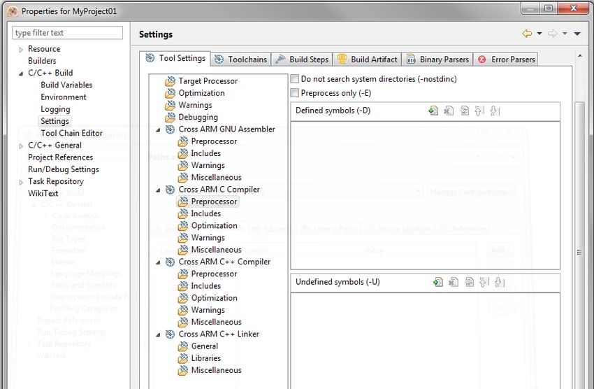
3. In the left-hand dialog (under the Devices tab), expand the All Devices > Freescale
(NXP) node.
4. Look for a line called "KVxx Series" and click it.
5. In the right-hand dialog (under the Packs tab), expand the Device Specific node.
6. Look for a node called "Keil::Kinetis_KVxx_DFP." If there are the Install or Update
options, click the button to install/update the package. See Figure 1-27.
7. When installed, the button has the "Up to date" title. Now close the Pack Installer.
Figure 1-27. Pack Installer
1.4.2 New project (without MCUXpresso SDK)
To start working on an application, create a new project. If the project already exists and
is opened, skip to the next section. Follow these steps to create a new project:
1. Launch Keil µVision.
2. In the main menu, select Project > New µVision Project…, and the Create New
Project dialog appears.
3. Navigate to the folder where you want to create the project, for example C:
\KeilProjects\MyProject01. Type the name of the project, for example MyProject01.
Click Save. See Figure 1-28.
GDFLIB User's Guide, Rev. 3, 05/2020
NXP Semiconductors 25Library integration into project (Keil µVision)
Figure 1-28. Create New Project dialog
4. In the next dialog, select the Software Packs in the very first box.
5. Type '' into the Search box, so that the device list is reduced to the devices.
6. Expand the node.
7. Click the MKV58F1M0xxx22 node, and then click OK. See Figure 1-29.
Figure 1-29. Select Device dialog
8. In the next dialog, expand the Device node, and tick the box next to the Startup node.
See Figure 1-30.
9. Expand the CMSIS node, and tick the box next to the CORE node.
GDFLIB User's Guide, Rev. 3, 05/2020
26 NXP SemiconductorsChapter 1 Library
Figure 1-30. Manage Run-Time Environment dialog
10. Click OK, and a new project is created. The new project is now visible in the left-
hand part of Keil µVision. See Figure 1-31.
Figure 1-31. Project
11. In the main menu, go to Project > Options for Target 'Target1'…, and a dialog
appears.
12. Select the Target tab.
13. Select Use Single Precision in the Floating Point Hardware option. See Figure 1-31.
Figure 1-32. FPU
GDFLIB User's Guide, Rev. 3, 05/2020
NXP Semiconductors 27Library integration into project (Keil µVision)
1.4.3 High-speed functions execution suppport
Some RT (or other) platforms contain high-speed functions execution support by
relocating all functions from the default Flash memory location to the RAM location for
much faster code access. The feature is important especially for devices with a slow Flash
interface. This section shows how to turn the RAM optimization feature support on and
off.
1. In the main menu, go to Project > Options for Target 'Target1'…, and a dialog
appears.
2. Select the C/C++ tab. See .
3. In the Include Preprocessor Symbols text box, type the following:
• RAM_OPTIM_HIGH—to turn the RAM optimization feature support on`
• RAM_OPTIM_MEDIUM—to turn the RAM optimization feature support on
• RAM_OPTIM_LOW—to turn the RAM optimization feature support on
If any of these three defines is defined, all RTCEL functions are put to the RAM,
regardless of which one is defined. The HIGH, MEDIUM, or LOW variants enable
separating the Flash or RAM locations from the other user code or application
functions. The RTCESL functions are always RAM-optimized if any variant is
defined.
Figure 1-33. Preprocessor symbols
4. Click OK in the main dialog.
The device reference manual shows how the__attribute__ ((section ("ram"))) atribute
works in connection with your device.
GDFLIB User's Guide, Rev. 3, 05/2020
28 NXP SemiconductorsChapter 1 Library
1.4.4 Linking the files into the project
GDFLIB requires MLIB to be included too. The following steps show how to include all
dependent modules.
To include the library files in the project, create groups and add them.
1. Right-click the Target 1 node in the left-hand part of the Project tree, and select Add
Group… from the menu. A new group with the name New Group is added.
2. Click the newly created group, and press F2 to rename it to RTCESL.
3. Right-click the RTCESL node, and select Add Existing Files to Group 'RTCESL'…
from the menu.
4. Navigate into the library installation folder C:\NXP\RTCESL
\CM7F_RTCESL_4.5_KEIL\MLIB\Include, and select the mlib_FP.h file. If the file
does not appear, set the Files of type filter to Text file. Click Add. See Figure 1-34.
Figure 1-34. Adding .h files dialog
5. Navigate to the parent folder C:\NXP\RTCESL\CM7F_RTCESL_4.5_KEIL\MLIB,
and select the mlib.lib file. If the file does not appear, set the Files of type filter to
Library file. Click Add. See Figure 1-35.
GDFLIB User's Guide, Rev. 3, 05/2020
NXP Semiconductors 29Library integration into project (Keil µVision)
Figure 1-35. Adding .lib files dialog
6. Navigate into the library installation folder C:\NXP\RTCESL
\CM7F_RTCESL_4.5_KEIL\GDFLIB\Include, and select the gdflib_FP.h file. If the
file does not appear, set the Files of type filter to Text file. Click Add.
7. Navigate to the parent folder C:\NXP\RTCESL\CM7F_RTCESL_4.5_KEIL
\GDFLIB, and select the gdflib.lib file. If the file does not appear, set the Files of
type filter to Library file. Click Add.
8. Now, all necessary files are in the project tree; see Figure 1-36. Click Close.
Figure 1-36. Project workspace
1.4.5 Library path setup
The following steps show the inclusion of all dependent modules.
1. In the main menu, go to Project > Options for Target 'Target1'…, and a dialog
appears.
2. Select the C/C++ tab. See Figure 1-37.
GDFLIB User's Guide, Rev. 3, 05/2020
30 NXP SemiconductorsChapter 1 Library
3. In the Include Paths text box, type the following paths (if there are more paths, they
must be separated by ';') or add them by clicking the … button next to the text box:
• "C:\NXP\RTCESL\CM7F_RTCESL_4.5_KEIL\MLIB\Include"
• "C:\NXP\RTCESL\CM7F_RTCESL_4.5_KEIL\GDFLIB\Include"
4. Click OK.
5. Click OK in the main dialog.
Figure 1-37. Library path addition
Type the #include syntax into the code. Include the library into a source file. In the new
project, it is necessary to create a source file:
1. Right-click the Source Group 1 node, and Add New Item to Group 'Source Group
1'… from the menu.
2. Select the C File (.c) option, and type a name of the file into the Name box, for
example 'main.c'. See Figure 1-38.
GDFLIB User's Guide, Rev. 3, 05/2020
NXP Semiconductors 31Library integration into project (IAR Embedded Workbench)
Figure 1-38. Adding new source file dialog
3. Click Add, and a new source file is created and opened up.
4. In the opened source file, include the following lines into the #include section, and
create a main function:
#include "mlib_FP.h"
#include "gdflib_FP.h"
int main(void)
{
while(1);
}
When you click the Build (F7) icon, the project will be compiled without errors.
1.5 Library integration into project (IAR Embedded
Workbench)
This section provides a step-by-step guide on how to quickly and easily include the
GDFLIB into an empty project or any MCUXpresso SDK example or demo application
projects using IAR Embedded Workbench. This example uses the default installation
path (C:\NXP\RTCESL\CM7F_RTCESL_4.5_IAR). If you have a different installation
path, use that path instead. If any MCUXpresso SDK project is intended to use (for
example hello_world project) go to Linking the files into the project chapter otherwise
read next chapter.
GDFLIB User's Guide, Rev. 3, 05/2020
32 NXP SemiconductorsChapter 1 Library
1.5.1 New project (without MCUXpresso SDK)
This example uses the NXP MKV58F1M0xxx22 part, and the default installation path
(C:\NXP\RTCESL\CM7F_RTCESL_4.5_IAR) is supposed. To start working on an
application, create a new project. If the project already exists and is opened, skip to the
next section. Perform these steps to create a new project:
1. Launch IAR Embedded Workbench.
2. In the main menu, select Project > Create New Project… so that the "Create New
Project" dialog appears. See Figure 1-39.
Figure 1-39. Create New Project dialog
3. Expand the C node in the tree, and select the "main" node. Click OK.
4. Navigate to the folder where you want to create the project, for example, C:
\IARProjects\MyProject01. Type the name of the project, for example, MyProject01.
Click Save, and a new project is created. The new project is now visible in the left-
hand part of IAR Embedded Workbench. See Figure 1-40.
GDFLIB User's Guide, Rev. 3, 05/2020
NXP Semiconductors 33Library integration into project (IAR Embedded Workbench)
Figure 1-40. New project
5. In the main menu, go to Project > Options…, and a dialog appears.
6. In the Target tab, select the Device option, and click the button next to the dialog to
select the MCU. In this example, select NXP > KV5x > NXP MKV58F1M0xxx22.
Select VFPv5 single precision in the FPU option. Click OK. See Figure 1-41.
Figure 1-41. Options dialog
GDFLIB User's Guide, Rev. 3, 05/2020
34 NXP SemiconductorsChapter 1 Library
1.5.2 High-speed functions execution suppport
Some RT (or other) platforms contain high-speed functions execution support by
relocating all functions from the default Flash memory location to the RAM location for
much faster code access. The feature is important especially for devices with a slow Flash
interface. This section shows how to turn the RAM optimization feature support on and
off.
1. In the main menu, go to Project > Options…, and a dialog appears.
2. In the left-hand side column, select C/C++ Compiler.
3. In the right-hand side of the dialog, click the Preprocessor tab (it can be hidden on
the right; use the arrow icons for navigation).
4. In the text box (in Defined symbols: (one per line)), type one of the following (See
Figure 1-42):
• RAM_OPTIM_HIGH—to turn the RAM optimization feature support on
• RAM_OPTIM_MEDIUM—to turn the RAM optimization feature support on
• RAM_OPTIM_LOW—to turn the RAM optimization feature support on
If any of these three defines is defined, all RTCEL functions are put to the RAM,
regardless of which one is defined. The HIGH, MEDIUM, or LOW variants can
separate the Flash or RAM locations of the other user code or application functions.
The RTCESL functions are always RAM-optimized if a variant is defined.
Figure 1-42. Defined symbols
5. Click OK in the main dialog.
The device reference manual shows how the __ramfunc atribute works in connection with
your device.
GDFLIB User's Guide, Rev. 3, 05/2020
NXP Semiconductors 35Library integration into project (IAR Embedded Workbench)
1.5.3 Library path variable
To make the library integration easier, create a variable that will hold the information
about the library path.
1. In the main menu, go to Tools > Configure Custom Argument Variables…, and a
dialog appears.
2. Click the New Group button, and another dialog appears. In this dialog, type the
name of the group PATH, and click OK. See Figure 1-43.
Figure 1-43. New Group
3. Click on the newly created group, and click the Add Variable button. A dialog
appears.
4. Type this name: RTCESL_LOC
5. To set up the value, look for the library by clicking the '…' button, or just type the
installation path into the box: C:\NXP\RTCESL\CM7F_RTCESL_4.5_IAR. Click
OK.
6. In the main dialog, click OK. See Figure 1-44.
GDFLIB User's Guide, Rev. 3, 05/2020
36 NXP SemiconductorsChapter 1 Library
Figure 1-44. New variable
1.5.4 Linking the files into the project
GDFLIB requires MLIB to be included too. The following steps show the inclusion of all
dependent modules.
To include the library files into the project, create groups and add them.
1. Go to the main menu Project > Add Group…
2. Type RTCESL, and click OK.
3. Click on the newly created node RTCESL, go to Project > Add Group…, and create
a MLIB subgroup.
4. Click on the newly created node MLIB, and go to the main menu Project > Add
Files… See Figure 1-46.
5. Navigate into the library installation folder C:\NXP\RTCESL
\CM7F_RTCESL_4.5_IAR\MLIB\Include, and select the mlib_FP.h file. (If the file
does not appear, set the file-type filter to Source Files.) Click Open. See Figure 1-45.
6. Navigate into the library installation folder C:\NXP\RTCESL
\CM7F_RTCESL_4.5_IAR\MLIB, and select the mlib.a file. If the file does not
appear, set the file-type filter to Library / Object files. Click Open.
Figure 1-45. Add Files dialog
7. Click on the RTCESL node, go to Project > Add Group…, and create a GDFLIB
subgroup.
GDFLIB User's Guide, Rev. 3, 05/2020
NXP Semiconductors 37Library integration into project (IAR Embedded Workbench)
8. Click on the newly created node GDFLIB, and go to the main menu Project > Add
Files….
9. Navigate into the library installation folder C:\NXP\RTCESL
\CM7F_RTCESL_4.5_IAR\GDFLIB\Include, and select the gdflib_FP.h file. (If the
file does not appear, set the file-type filter to Source Files.) Click Open.
10. Navigate into the library installation folder C:\NXP\RTCESL
\CM7F_RTCESL_4.5_IAR\GDFLIB, and select the gdflib.a file. If the file does not
appear, set the file-type filter to Library / Object files. Click Open.
11. Now you will see the files added in the workspace. See Figure 1-46.
Figure 1-46. Project workspace
1.5.5 Library path setup
The following steps show the inclusion of all dependent modules:
1. In the main menu, go to Project > Options…, and a dialog appears.
2. In the left-hand column, select C/C++ Compiler.
3. In the right-hand part of the dialog, click on the Preprocessor tab (it can be hidden in
the right; use the arrow icons for navigation).
4. In the text box (at the Additional include directories title), type the following folder
(using the created variable):
• $RTCESL_LOC$\MLIB\Include
• $RTCESL_LOC$\GDFLIB\Include
5. Click OK in the main dialog. See Figure 1-47.
GDFLIB User's Guide, Rev. 3, 05/2020
38 NXP SemiconductorsChapter 1 Library
Figure 1-47. Library path adition
Type the #include syntax into the code. Include the library included into the main.c file.
In the workspace tree, double-click the main.c file. After the main.c file opens up, include
the following lines into the #include section:
#include "mlib_FP.h"
#include "gdflib_FP.h"
When you click the Make icon, the project will be compiled without errors.
GDFLIB User's Guide, Rev. 3, 05/2020
NXP Semiconductors 39Library integration into project (IAR Embedded Workbench)
GDFLIB User's Guide, Rev. 3, 05/2020
40 NXP SemiconductorsChapter 2
Algorithms in detail
2.1 GDFLIB_FilterExp
The GDFLIB_FilterExp function calculates the exponential smoothing. The exponential
filter is the simplest filter with only one tuning parameter, requiring to store only one
variable - the filter output (it is used in the next step). For a proper use, it is recommended
that the algorithm is initialized by the GDFLIB_FilterExpInit function, before using the
GDFLIB_FilterExp function.
The filter calculation consists of the following equation:
Equation 1.
where:
• x(k) is the actual value of the input signal
• y(k) is the actual filter output
• A is the filter constant (0 ; 1) (it defines the smoothness of the exponential filter)
The exponential filter tuning is based on these rules: for a small value of the filter
constant there is a strong filtering effect (if A = 0 then the output equals the new input).
For a high value of the filtering constant, there is a weak filtering effect (if A = 1 then the
new input is ignored). The filter constant defines the ratio between the filter inputs and
the last step output, used for the next calculation.
2.1.1 Available versions
This function is available in the following versions:
GDFLIB User's Guide, Rev. 3, 05/2020
NXP Semiconductors 41GDFLIB_FilterExp
• Fractional output - the output is the fractional portion of the result; the result is
within the rangeChapter 2 Algorithms in detail
2.1.2 GDFLIB_FILTER_EXP_T_F32
Variable Input Description
name type
f32A frac32_t Filter constant value (filter parameter). It defines the smoothness of the exponential filter (high value
= small filtering effect, low value = strong filtering effect). It is usually defined as:
Where Ts is the sample time and τ is the filter time constant. The parameter is a 32-bit fractional
value within the rangeGDFLIB_FilterExp
2.1.5 Function use
The use of the GDFLIB_FilterExpInit and GDFLIB_FilterExp functions is shown in the
following examples:
Fixed-point version:
#include "gdflib.h"
static frac16_t f16Result;
static frac16_t f16InitVal, f16InX;
static GDFLIB_FILTER_EXP_T_F32 sFilterParam;
void Isr(void);
void main(void)
{
f16InitVal = FRAC16(0.0); /* f16InitVal = 0.0 */
/* Filter constant = 0.05 */
sFilterParam.f32A = FRAC32(0.05);
GDFLIB_FilterExpInit_F16(f16InitVal, &sFilterParam);
f16InX = FRAC16(0.5);
}
/* periodically called function */
void Isr(void)
{
f16Result = GDFLIB_FilterExp_F16(f16InX, &sFilterParam);
}
Floating-point version:
#include "gdflib.h"
static float_t fltResult;
static float_t fltInitVal, fltInX;
static GDFLIB_FILTER_EXP_T_FLT sFilterParam;
void Isr(void);
void main(void)
{
fltInitVal = 0.0F; /* fltInitVal = 0.0 */
/* Filter constant = 0.05 */
sFilterParam.fltA = 0.05F;
GDFLIB_FilterExpInit_FLT(fltInitVal, &sFilterParam);
fltInX = 0.5F;
}
/* periodically called function */
void Isr(void)
{
fltResult = GDFLIB_FilterExp_FLT(fltInX, &sFilterParam);
}
GDFLIB User's Guide, Rev. 3, 05/2020
44 NXP SemiconductorsChapter 2 Algorithms in detail
2.2 GDFLIB_FilterIIR1
This function calculates the first-order direct form 1 IIR filter.
For a proper use, it is recommended that the algorithm is initialized by the
GDFLIB_FilterIIR1Init function, before using the GDFLIB_FilterIIR1 function. The
GDFLIB_FilterIIR1Init function initializes the buffer and coefficients of the first-order
IIR filter.
The GDFLIB_FilterIIR1 function calculates the first-order infinite impulse response
(IIR) filter. The IIR filters are also called recursive filters, because both the input and the
previously calculated output values are used for calculation. This form of feedback
enables the transfer of energy from the output to the input, which leads to an infinitely
long impulse response (IIR). A general form of the IIR filter, expressed as a transfer
function in the Z-domain, is described as follows:
Equation 2.
where N denotes the filter order. The first-order IIR filter in the Z-domain is expressed as
follows:
Equation 3.
which is transformed into a time-domain difference equation as follows:
Equation 4.
The filter difference equation is implemented in the digital signal controller directly, as
given in Equation 4 on page 45; this equation represents a direct-form 1 first-order IIR
filter, as shown in Figure 2-1.
Figure 2-1. Direct form 1 first-order IIR filter
GDFLIB User's Guide, Rev. 3, 05/2020
NXP Semiconductors 45GDFLIB_FilterIIR1
The coefficients of the filter shown in Figure 2-1 can be designed to meet the
requirements for the first-order low-pass filter (LPF) or high-pass filter (HPF). The
coefficient quantization error is not important in the case of a first-order filter due to a
finite precision arithmetic. A higher-order LPF or HPF can be obtained by connecting a
number of first-order filters in series. The number of connections gives the order of the
resulting filter.
The filter coefficients must be defined before calling this function. As some coefficients
can be greater than 1 (and lesser than 2), the coefficients are scaled down (divided) by 2.0
for the fractional version of the algorithm. For faster calculation, the A coefficient is sign-
inverted. The function returns the filtered value of the input in the step k, and stores the
input and the output values in the step k into the filter buffer.
2.2.1 Available versions
This function is available in the following versions:
• Fractional output - the output is the fractional portion of the result; the result is
within the rangeChapter 2 Algorithms in detail
The available versions of the GDFLIB_FilterIIR1 function are shown in the following
table:
Table 2-4. Function versions
Function name Input Parameters Result Description
type type
GDFLIB_FilterIIR1_F16 frac16_t GDFLIB_FILTER_IIR1_T_F32 * frac16_t The input argument is a 16-bit
fractional value of the input signal to
be filtered within the rangeGDFLIB_FilterIIR1
2.2.4 GDFLIB_FILTER_IIR1_T_FLT
Variable name Input type Description
sFltCoeff GDFLIB_FILTER_IIR1_COEFF_T_FLT * Substructure containing filter coefficients.
fltFltBfrY[1] float_t Internal buffer of y-history. Controlled by the
algorithm.
fltFltBfrX[1] float_t Internal buffer of x-history. Controlled by the
algorithm.
2.2.5 GDFLIB_FILTER_IIR1_COEFF_T_FLT
Variable name Type Description
fltB0 float_t B0 coefficient of the IIR1 filter. Set by the user.
fltB1 float_t B1 coefficient of the IIR1 filter. Set by the user.
fltA1 float_t A1 (sign-inverted) coefficient of the IIR1 filter. Set by the user.
2.2.6 Declaration
The available GDFLIB_FilterIIR1Init functions have the following declarations:
void GDFLIB_FilterIIR1Init_F16(GDFLIB_FILTER_IIR1_T_F32 *psParam)
void GDFLIB_FilterIIR1Init_FLT(GDFLIB_FILTER_IIR1_T_FLT *psParam)
The available GDFLIB_FilterIIR1 functions have the following declarations:
frac16_t GDFLIB_FilterIIR1_F16(frac16_t f16InX, GDFLIB_FILTER_IIR1_T_F32 *psParam)
float_t GDFLIB_FilterIIR1_FLT(float_t fltInX, GDFLIB_FILTER_IIR1_T_FLT *psParam)
2.2.7 Calculation of filter coefficients
There are plenty of methods for calculating the coefficients. The following example
shows the use of Matlab to set up a low-pass filter with the 500 Hz sampling frequency,
and 240 Hz stopped frequency with a 20 dB attenutation. Maximum passband ripple is 3
dB at the cut-off frequency of 50 Hz.
% sampling frequency 500 Hz, low pass
Ts = 1 / 500
% cut-off frequency 50 Hz
Fc = 50
GDFLIB User's Guide, Rev. 3, 05/2020
48 NXP SemiconductorsChapter 2 Algorithms in detail
% max. passband ripple 3 dB
Rp = 3
% stopped frequency 240Hz
Fs = 240
% attenuation 20 dB
Rs = 20
% checking order of the filter
n = buttord(2 * Ts * Fc, 2 * Ts * Fs, Rp, Rs)
% n = 1, i.e. the filter is achievable with the 1st order
% getting the filter coefficients
[b, a] = butter(n, 2 * Ts * Fc, 'low');
% the coefs are:
% b0 = 0.245237275252786, b1 = 0.245237275252786
% a0 = 1.0000, a1 = -0.509525449494429
The filter response is shown in Figure 2-2.
Figure 2-2. Filter response
2.2.8 Function use
The use of the GDFLIB_FilterIIR1Init and GDFLIB_FilterIIR1 functions is shown in the
following examples. The filter uses the above-calculated coefficients:
Fixed-point version:
GDFLIB User's Guide, Rev. 3, 05/2020
NXP Semiconductors 49GDFLIB_FilterIIR2
#include "gdflib.h"
static frac16_t f16Result;
static frac16_t f16InX;
static GDFLIB_FILTER_IIR1_T_F32 sFilterParam;
void Isr(void);
void main(void)
{
sFilterParam.sFltCoeff.f32B0 = FRAC32(0.245237275252786 / 2.0);
sFilterParam.sFltCoeff.f32B1 = FRAC32(0.245237275252786 / 2.0);
sFilterParam.sFltCoeff.f32A1 = FRAC32(-0.509525449494429 / -2.0);
GDFLIB_FilterIIR1Init_F16(&sFilterParam);
f16InX = FRAC16(0.1);
}
/* periodically called function */
void Isr(void)
{
f16Result = GDFLIB_FilterIIR1_F16(f16InX, &sFilterParam);
}
Floating-point version:
#include "gdflib.h"
static float_t fltResult;
static float_t fltInX;
static GDFLIB_FILTER_IIR1_T_FLT sFilterParam;
void Isr(void);
void main(void)
{
sFilterParam.sFltCoeff.fltB0 = 0.245237275252786f;
sFilterParam.sFltCoeff.fltB1 = 0.245237275252786f;
sFilterParam.sFltCoeff.fltA1 = -0.509525449494429f;
GDFLIB_FilterIIR1Init_FLT(&sFilterParam);
fltInX = 0.1F;
}
/* periodically called function */
void Isr(void)
{
fltResult = GDFLIB_FilterIIR1_FLT(fltInX, &sFilterParam);
}
2.3 GDFLIB_FilterIIR2
This function calculates the second-order direct-form 1 IIR filter.
GDFLIB User's Guide, Rev. 3, 05/2020
50 NXP SemiconductorsChapter 2 Algorithms in detail
For a proper use, it is recommended that the algorithm is initialized by the
GDFLIB_FilterIIR2Init function, before using the GDFLIB_FilterIIR2 function. The
GDFLIB_FilterIIR2Init function initializes the buffer and coefficients of the second-
order IIR filter.
The GDFLIB_FilterIIR2 function calculates the second-order infinite impulse response
(IIR) filter. The IIR filters are also called recursive filters, because both the input and the
previously calculated output values are used for calculation. This form of feedback
enables the transfer of energy from the output to the input, which leads to an infinitely
long impulse response (IIR). A general form of the IIR filter, expressed as a transfer
function in the Z-domain, is described as follows:
Equation 5.
where N denotes the filter order. The second-order IIR filter in the Z-domain is expressed
as follows:
Equation 6.
which is transformed into a time-domain difference equation as follows:
Equation 7.
The filter difference equation is implemented in the digital signal controller directly, as
given in Equation 7 on page 51; this equation represents a direct-form 1 second-order IIR
filter, as depicted in Figure 2-3.
Figure 2-3. Direct-form 1 second-order IIR filter
GDFLIB User's Guide, Rev. 3, 05/2020
NXP Semiconductors 51GDFLIB_FilterIIR2
The coefficients of the filter depicted in Figure 2-3 can be designed to meet the
requirements for the second-order low-pass filter (LPF), high-pass filter (HPF), band-pass
filter (BPF) or band-stop filter (BSF). The coefficient quantization error can be neglected
in the case of a second-order filter due to a finite precision arithmetic. A higher-order
LPF or HPF can be obtained by connecting a number of second-order filters in series.
The number of connections gives the order of the resulting filter.
The filter coefficients must be defined before calling this function. As some coefficients
can be greater than 1 (and lesser than 2), the coefficients are scaled down (divided) by 2.0
for the fractional version of the algorithm. For faster calculation, the A coefficients are
sign-inverted. The function returns the filtered value of the input in the step k, and stores
the input and output values in the step k into the filter buffer.
2.3.1 Available versions
This function is available in the following versions:
• Fractional output - the output is the fractional portion of the result; the result is
within the rangeChapter 2 Algorithms in detail
The available versions of the GDFLIB_FilterIIR2 function are shown in the following
table:
Table 2-6. Function versions
Function name Input Parameters Result Description
type type
GDFLIB_FilterIIR2_F16 frac16_t GDFLIB_FILTER_IIR2_T_F32 * frac16_t Input argument is a 16-bit fractional
value of the input signal to be filtered
within the rangeGDFLIB_FilterIIR2
2.3.4 GDFLIB_FILTER_IIR2_T_FLT
Variable name Input type Description
sFltCoeff GDFLIB_FILTER_IIR2_COEFF_T_FLT * Substructure containing filter coefficients.
fltFltBfrY[2] float_t Internal buffer of y-history. Controlled by the
algorithm.
fltFltBfrX[2] float_t Internal buffer of x-history. Controlled by the
algorithm.
2.3.5 GDFLIB_FILTER_IIR2_COEFF_T_FLT
Variable name Type Description
fltB0 float_t B0 coefficient of the IIR2 filter. Set by the user.
fltB1 float_t B1 coefficient of the IIR2 filter. Set by the user.
fltB2 float_t B2 coefficient of the IIR2 filter. Set by the user.
fltA1 float_t A1 (sign-inverted) coefficient of the IIR2 filter. Set by the user.
fltA2 float_t A2 (sign-inverted) coefficient of the IIR2 filter. Set by the user.
2.3.6 Declaration
The available GDFLIB_FilterIIR2Init functions have the following declarations:
void GDFLIB_FilterIIR2Init_F16(GDFLIB_FILTER_IIR2_T_F32 *psParam)
void GDFLIB_FilterIIR2Init_FLT(GDFLIB_FILTER_IIR2_T_FLT *psParam)
The available GDFLIB_FilterIIR2 functions have the following declarations:
frac16_t GDFLIB_FilterIIR2_F16(frac16_t f16InX, GDFLIB_FILTER_IIR2_T_F32 *psParam)
float_t GDFLIB_FilterIIR2_FLT(float_t fltInX, GDFLIB_FILTER_IIR2_T_FLT *psParam)
2.3.7 Calculation of filter coefficients
There are plenty of methods for calculating the coefficients. The following example
shows the use of Matlab to set up a stopband filter with the 1000 Hz sampling frequency,
100 Hz stop frequency with 10 dB attenuation, and 30 Hz bandwidth. Maximum
passband ripple is 3 dB.
GDFLIB User's Guide, Rev. 3, 05/2020
54 NXP SemiconductorsChapter 2 Algorithms in detail
% sampling frequency 1000 Hz, stop band
Ts = 1 / 1000
% center stop frequency 100 Hz
Fc = 50
% attenuation 10 dB
Rs = 10
% bandwidth 30 Hz
Fbw = 30
% max. passband ripple 3 dB
Rp = 3
% checking order of the filter
n = buttord(2 * Ts * [Fc - Fbw /2 Fc + Fbw / 2], 2 * Ts * [Fc - Fbw Fc + Fbw], Rp, Rs)
% n = 2, i.e. the filter is achievable with the 2nd order
% getting the filter coefficients
[b, a] = butter(n / 2, 2 * Ts * [Fc - Fbw /2 Fc + Fbw / 2], 'stop')
% the coefs are:
% b0 = 0.913635972986238, b1 = -1.745585863109291, b2 = 0.913635972986238
% a0 = 1.0000, a1 = -1.745585863109291, a2 = 0.827271945972476
The filter response is shown in Figure 2-4.
Figure 2-4. Filter response
2.3.8 Function use
The use of the GDFLIB_FilterIIR2Init and GDFLIB_FilterIIR2 functions is shown in the
following examples. The filter uses the above-calculated coefficients:
GDFLIB User's Guide, Rev. 3, 05/2020
NXP Semiconductors 55GDFLIB_FilterIIR2
Fixed-point version:
#include "gdflib.h"
static frac16_t f16Result;
static frac16_t f16InX;
static GDFLIB_FILTER_IIR2_T_F32 sFilterParam;
void Isr(void);
void main(void)
{
sFilterParam.sFltCoeff.f32B0 = FRAC32(0.913635972986238 / 2.0);
sFilterParam.sFltCoeff.f32B1 = FRAC32(-1.745585863109291 / 2.0);
sFilterParam.sFltCoeff.f32B2 = FRAC32(0.913635972986238 / 2.0);
sFilterParam.sFltCoeff.f32A1 = FRAC32(-1.745585863109291 / -2.0);
sFilterParam.sFltCoeff.f32A2 = FRAC32(0.827271945972476 / -2.0);
GDFLIB_FilterIIR2Init_F16(&sFilterParam);
f16InX = FRAC16(0.1);
}
/* periodically called function */
void Isr(void)
{
f16Result = GDFLIB_FilterIIR2_F16(f16InX, &sFilterParam);
}
Floating-point version:
#include "gdflib.h"
static float_t fltResult;
static float_t fltInX;
static GDFLIB_FILTER_IIR2_T_FLT sFilterParam;
void Isr(void);
void main(void)
{
sFilterParam.sFltCoeff.fltB0 = 0.913635972986238f;
sFilterParam.sFltCoeff.fltB1 = -1.745585863109291f;
sFilterParam.sFltCoeff.fltB2 = 0.913635972986238f;
sFilterParam.sFltCoeff.fltA1 = -1.745585863109291f;
sFilterParam.sFltCoeff.fltA2 = 0.827271945972476f;
GDFLIB_FilterIIR2Init_FLT(&sFilterParam);
fltInX = 0.1F;
}
/* periodically called function */
void Isr(void)
{
fltResult = GDFLIB_FilterIIR2_FLT(fltInX, &sFilterParam);
}
GDFLIB User's Guide, Rev. 3, 05/2020
56 NXP SemiconductorsChapter 2 Algorithms in detail
2.4 GDFLIB_FilterIIR3
This function calculates the third-order direct-form 1 IIR filter.
For a proper use, it is recommended to initialize the algorithm by the
GDFLIB_FilterIIR3Init function before using the GDFLIB_FilterIIR3 function. The
GDFLIB_FilterIIR3Init function initializes the buffer and coefficients of the third-order
IIR filter.
The GDFLIB_FilterIIR3 function calculates the third-order infinite impulse response
(IIR) filter. The IIR filters are also called recursive filters because both the input and the
previously calculated output values are used for calculation. This form of feedback
enables the transfer of energy from the output to the input, which leads to an infinitely
long impulse response (IIR). A general form of the IIR filter (expressed as a transfer
function in the Z-domain) is described as follows:
Equation 8.
where N denotes the filter order. The third-order IIR filter in the Z-domain is expressed
as follows:
Equation 9.
which is transformed into a time-domain difference equation as follows:
Equation 10.
The filter difference equation is implemented in the digital signal controller directly, as
given in Equation 10 on page 57. This equation represents a direct-form 1 third-order IIR
filter, as depicted in Figure 2-5.
GDFLIB User's Guide, Rev. 3, 05/2020
NXP Semiconductors 57You can also read