Persona The Personalized Knee - Surgical Technique - Quality-1 Export
←
→
Page content transcription
If your browser does not render page correctly, please read the page content below
Persona®
The Personalized Knee
                Surgical Technique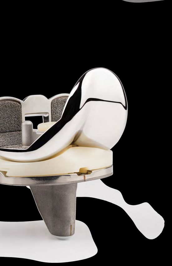
Table of Contents

         Introduction............................................................................................................... 2
              Constraint Options
              Preoperative Planning
              Surgical Approach
              Patient Preparation
              Magnet Usage
              Symbols
              Screw/Pin Information

         Resect Distal Femur................................................................................................... 6
             Assemble Adjustable Distal Resection Instrumentation
             Establish Femoral Alignment
             Resect Distal Femur
             Optional Instrument
             Optional Cutting Technique

         Resect Proximal Tibia.............................................................................................. 12
             Assemble Extramedullary (EM) Alignment Guide
             Position Alignment Guide
             Set Resection Level
             Resect Proximal Tibia
             Optional Technique

         Size Femur and Establish External Rotation........................................................... 19

         Complete Femoral A/P and Chamfer Resections................................................... 22
            Optional Instrument

         Establish Size and Rotation of Tibia......................................................................... 24

         Drill and Broach Tibia.............................................................................................. 25
              Optional Technique

         Prepare the Patella.................................................................................................. 28

         Resect the Patella.................................................................................................... 28

         Finish the Patella...................................................................................................... 29

         CR Femoral Finishing and Trialing........................................................................... 31

         PS Femoral Finishing and PS Box Preparation........................................................ 33

         Perform Trial Reduction........................................................................................... 38
Table of Contents (cont.)
Tibial Articular Surface Provisional (TASP) Assembly............................................. 39
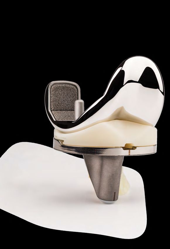
Implant Components............................................................................................... 43
Tibial Plate
Femoral Component
Bearing
Patellar Component
All-Polyethylene Patella
Close Incision........................................................................................................... 46
Surgeon Notes and Tips
Appendix A............................................................................................................... 47
2 Degrees Valgus Recut Guide
2 Degrees Varus Recut Guide
Appendix B............................................................................................................... 49
Spacer Block Technique
Appendix C: Optional Instruments.......................................................................... 52
Resect Distal Femur: Fixed Distal Resection Instrument
Size Femur - Anterior Referencing Sizer
Shift Block
Resect Distal Femur - PRI Distal Resection Instrument
Implant Components - Attached Tibial Plate Inserter
Appendix D.............................................................................................................. 66
Compatibility Charts
Surgical Technique
2 | Persona The Personalized Knee Surgical Technique

    Introduction

    Successful total knee arthroplasty depends in part on      The CR femoral provisionals and components can
    re-establishment of normal lower extremity alignment,      be used when the PCL is sacrificed or deficient and
    proper implant design and orientation, secure implant      removed, if used with either a MC or ultracongruent
    fixation, and adequate soft tissue balancing and           (UC) bearing provisionals and components.
    stability. Persona The Personalized Knee is designed to
    help the surgeon accomplish these goals by combining       Also, posterior stabilized (PS) femoral provisionals and
    alignment accuracy with a simple, straight-forward         components can be used with the PS or constrained
    technique.                                                 posterior stabilized (CPS) bearings provisionals and
                                                               components when the PCL is deficient and removed.
    T he instruments and technique assist the surgeon in
     restoring the center of the hip, knee, and ankle to lie   PS femoral components cannot be used with CR, MC,
     in a straight line, establishing a neutral mechanical     or UC bearings and CR femoral components cannot be
     axis. The femoral and tibial components are               used with PS or CPS bearings.
     oriented perpendicular to this axis. Femoral rotation     The CPS bearings can be used to provide moderate
     is determined using the posterior condyles, the           varus\valgus constraint in patients to facilitate soft
     epicondylar axis, or Whiteside’s line as a reference.     tissue balance and stability. The CPS bearings shall
     The instruments enable accurate cuts to ensure robust     be used with cemented non-porous femoral and tibial
     component fixation.                                       components only. Additional information for this
    A wide variety of component sizes, shapes, and             product may be found in the Constrained Posterior
    constraint options allow for optimized component fit       Stabilized (CPS) Surgical Technique (97-5026-072-00).
    and soft tissue balancing. The femur, tibia, and patella   The MC, UC, PS, and CPS implants can be used in
    are prepared independently, and can be cut in any          the following situations, depending on the degree
    sequence using the principle of measured resection         of the deformity, the stability of the ligaments, and
    (removing enough bone to allow replacement by the          the quality of the bone. The surgeon is responsible
    prosthesis). Adjustment cuts may be needed later. The      for assessing whether a more constraining implant/
    anterior referencing technique uses the anterior cortex    system or revision implant/system is necessary.
    to set the A/P position of the femoral component. The
    posterior condyle cut is variable.                            Marked valgus deformity – requiring PCL
                                                               1.
                                                                  and lateral soft tissue release.

    Constraint Options                                         2. P
                                                                   rior high tibial osteotomies – soft tissue
                                                                  balancing is the same as for a valgus deformity
    The degree of constraint of the bearing can be
                                                                  with lateral soft tissue and PCL release.
    planned based on surgeon preference and patient
    requirements. The use of the cruciate retaining (CR)       3. Patellectomy – PCL incomplete or absent.
    femoral provisionals and components can be used with
    either a CR or Medial Congruent® (MC) bearing when         4. Most revision situations – PCL deficient
    the posterior cruciate ligament (PCL) is intact.              or nonfunctional.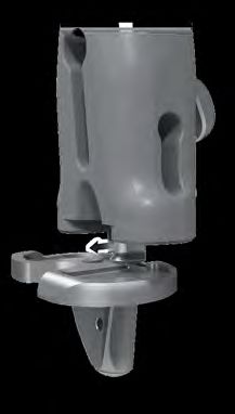
3 | Persona The Personalized Knee Surgical Technique

Introduction (cont.)
                                                            Patient Preparation
   Note: The MC components can be used with or              To prepare the limb for total knee arthroplasty,
   without the PCL present. The UC, PS, and CPS             adequate muscle relaxation is required. The
   components should not be used if the PCL is              anesthesiologist should adjust the medication based
   present.                                                 on the patient’s habitus and weight, and administer
                                                            to induce adequate muscle paralysis for a minimum
Please refer to the package inserts for complete            of 30-40 minutes. It is imperative that the muscle
product information, including contraindications,           relaxant be injected prior to inflation of the tourniquet.
warnings, precautions, and adverse effects.                 Alternatively, spinal or epidural anesthesia should
                                                            produce adequate muscle relaxation. If desired, apply
                                                            a proximal thigh tourniquet and inflate it with the
Preoperative Planning                                       knee in hyperflexion to maximize that portion of the
Obtain 36 inch or 53 inch standing anteroposterior          quadriceps that is below the level of the tourniquet.
and lateral radiographs of the extremity, as well as a      Once the patient is draped and prepped on the
sunrise view of the patella. The entire femur should        operating table, determine the landmarks for the
be visualized to rule out any structural abnormalities,     surgical incision.
as the distal femoral cut will be referenced from an
intramedullary rod in the medullary canal.

Use the template overlay (available through your
Zimmer Biomet representative) to determine the
angle between the anatomic axis and the mechanical
axis. This angle will be reproduced intraoperatively.
This surgical technique helps the surgeon ensure
that the distal femur will be cut perpendicular to the
mechanical axis and, after soft tissue balancing, will be
parallel to the resected surface of the proximal tibia.

Surgical Approach
The surgeon can choose a midvastus approach, a
subvastus approach, or a parapatellar medial
arthrotomy. Also, depending on surgeon preference,
the patella can be either everted or subluxed. The
femur, tibia, and patella are prepared independently,
and can be cut in any sequence using the principle of
measured resection (removing enough bone to allow
replacement by the prosthesis).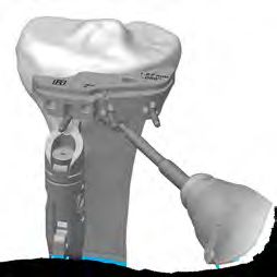
4 | Persona The Personalized Knee Surgical Technique

    Introduction (cont.)
    Magnet Usage
    Warning: Some instruments in the Persona System
    contain magnets. All Persona Magnetic Instruments
    should be kept at a safe distance from a patient’s
    active implantable medical device(s) (i.e. pacemaker).
    These types of devices may be adversely affected by
    magnets. Instruments containing magnets should be
    kept on an appropriate table or stand when not in use
    at the surgical site.

    Symbols
    Symbols have been established for the following:
                                                                  Left            Right         Varus/Valgus
    • Left

    • Right

    • Varus/Valgus                                            M/L               Std
                                                             Medial/Lateral     Standard       Do not implant -
    • Medial/Lateral                                                                           Not for implant

    • Standard

    • Do not implant - Not for implant

    • Do not impact                                          Do not impact      Inset Only   Anterior Referencing

    • Inset Only

    • Anterior Referencing

    • Lock
                                                                         Lock                Unlock
    • Unlock

    • Cemented
                                                               Cemented          Stemmed              Narrow
    • Stemmed

    • Narrow
5 | Persona The Personalized Knee Surgical Technique
Introduction (cont.)
Screw/Pin Information
The chart below contains relevant information on various 3.2 mm
screws/pins that are compatible with the Persona System. If these
screws/pins are used during the procedure for instrument fixation,
they should be removed prior to closure as they are NOT implantable.
Shipped Sterile/ Quantity
Screw/Pin Screw/Pin Item # Compatible Driver Non-sterile per Package Single use?
25 mm x 2.5 mm Sterile 2 Yes
Female Hex Screw 2.5 mm Male Hex Driver
42-5099-025-25* 42-5099-025-00
75 mm x 3.2 mm Sterile 4 Yes
Trocar Tipped Drill Pin/Screw Inserter
Pin (2.5 mm hex) 00-5901-021-00
00-5901-020-00
Hex Headed Screw Sterile 2 Yes
33 mm long Pin/Screw Inserter
00-5901-035-33 00-5901-021-00
MIS Quad-Sparing™ Sterile 1 Yes
Total Knee Headed Screw Inserter/Extractor
Screw 48 mm long 00-5983-049-00
00-5983-040-48
25 mm Shorthead Non-Sterile 1 No
Holding Pin
00-5977-056-03 Multi Pin Puller
00-5901-022-00
* The 2.5 mm female hex screws and 2.5 mm male hex driver should not be used in cortical bone,
as this may increase the incidence of stripping of the driver.6 | Persona The Personalized Knee Surgical Technique
1. Pull
Caution
Marking
2. Insert
Figure 3
Figure 1
Rotate Dial
2. Rotate
1. Press
Shown at '0' setting
Figure 2 Figure 4
Resect Distal Femur
Assemble Adjustable Distal Resection
Instrumentation
Pull the lever on the modular handle and insert the IM Insert the IM rod into the adjustable valgus guide.
rod (Figure 1). Orientation of the IM rod will align with
the polished line on the sides of the modular handle. Note: If desired, align the depth markings on the IM
rod with the flat plate of the adjustable valgus guide
Technique Tip: Alternately, the IM rod may be to set the IM rod at a specific length. Inserting the
inserted into the top of the modular handle to IM rod beyond the double line marking, indicated
accommodate surgical preference. with caution symbols, may prevent assembly of the
modular handle to the IM rod (Figure 3).
Set the valgus angle on the adjustable valgus guide
by pressing the button and rotating the dial to the efer to Appendix C for Optional Instruments to
R
appropriate left or right valgus angle from 0 degrees resect the distal femur.
to 9 degrees (Figure 2).
S et the resection depth on the adjustable resection
Avoid turning the locking knob excessively in the tower by rotating the dial (Figure 4). The ‘0’ setting
counterclockwise, or "unlocking", direction to prevent indicates a 10 mm resection. Adjustments can be
it from binding. made in 1 mm increments from 10 mm to 14 mm.
Persona 8 mm IM Rod Persona Modular Handle Persona Valgus Alignment Guide Persona Adjustable Resection Tower
42-5099-002-00 42-5099-014-00 42-5099-004-00 42-5099-008-007 | Persona The Personalized Knee Surgical Technique
2. Insert 1. Unlock
Figure 6a
Lock
Figure 5 Figure 6b
Resect Distal Femur (cont.)
Assemble Adjustable Distal Resection
Instrumentation (cont.)
Note: The ‘0’ setting can be set to indicate a 1 mm Insert the adjustable resection tower into the
through 9 mm resection depth, in 1 mm increments, adjustable valgus guide.
by assembling the corresponding resection plate to
the valgus guide. Figure 5 illustrates this with the 9 otate the lock lever on the adjustable resection tower
R
mm resection plate. The 9 mm and 8 mm resection to the unlocked, or “in-line”, position and fully insert
plates may facilitate correction of recurvatum and into the cut guide (Figure 6a). Flip the lock lever to the
the 1 mm–3 mm resection plates can be used for locked, or “vertical”, position to secure it to the cut
recutting the distal femur, if needed. guide (Figure 6b).
Technique Tip: The adjustable resection tower
The size 1 and 2 femoral components are 1 mm
is compatible with the fixed valgus guide and
thinner distally than sizes 3-12. Consider adjusting
the fixed resection tower is compatible with the
the resection depth on these sizes to accommodate
adjustable valgus guide. These instruments can be
for this difference.
interchanged to accommodate surgical preference.
Technique Tip: If it is possible that the femoral
component may be a size 1 or 2, then consider
cutting the distal resection for a size 1 or 2. If the
size of the femur is later determined to be 3-12, then
the additional bone cut can be made using the 1 mm
resection plate.
Persona 8 mm IM Rod Persona Modular Handle Persona Valgus Alignment Persona Adjustable Persona 0° Distal Cut Guide Persona 9 mm Distal
42-5099-002-00 42-5099-014-00 Guide Resection Tower 42-5099-010-00 Resection Plate
42-5099-004-00 42-5099-008-00 42-5099-015-098 | Persona The Personalized Knee Surgical Technique
Figure 7 Figure 8a Figure 8b
Resect Distal Femur (cont.)
Establish Femoral Alignment
rill the IM canal using the 8 mm IM step drill
D S et the orientation of the adjustable valgus guide by
(Figure 7). Suction the canal to remove medullary placing it against the most prominent distal condyle
contents. and rotating it about the IM rod so that the engraved
lines are aligned with the epicondylar axis (Figure 8a).
Insert the IM rod and assembled distal resection
instrumentation into the IM canal far enough to ensure Turn the lock knob on the adjustable valgus guide
the most accurate replication of the anatomic axis. clockwise, to the locked position, to secure orientation
of the assembly (Figure 8b).
Note: Setting rotation of the adjustable valgus
guide is important for creating a distal resection
that matches the desired valgus angle selected. It
does not set the rotation of the femoral component.
8 mm IM Step Drill Persona 8 mm IM Rod Persona Modular Handle Persona Valgus Alignment Guide Persona Adjustable Resection Tower
00-5978-014-00 42-5099-002-00 42-5099-014-00 42-5099-004-00 42-5099-008-00
Persona 0° Distal Cut Guide
42-5099-010-009 | Persona The Personalized Knee Surgical Technique
Figure 9
Rotate Dial
"Click"
Figure 10 Figure 11
Resect Distal Femur (cont.)
Establish Femoral Alignment (cont.)
For additional fixation, or in lieu of using the lock knob, Technique Tip: If unsure of the adjustable
impact the captured pin on the medial or lateral side resection tower depth setting, rotate the dial
of the adjustable valgus guide until the head of the clockwise until a “click” is felt. This occurs when
captured pin is flush with the plate (Figure 9). the dial moves from the ‘4’ setting to the ‘0’ setting.
The bold ‘0’ will be visible on the dial and the line
will be aligned with the ‘0’ mark along the shaft
Resect Distal Femur (Figure 10).
erify the adjustable valgus guide is set to the proper
V
side (left or right) and angle and that the adjustable Technique Tip: Confirm valgus alignment by
resection tower is set to the appropriate depth. inserting the drop rod adapter into the large holes
on the anterior face of the cut guide and insert an
alignment rod into the drop rod adapter (Figure 11).
Persona 8 mm IM Rod Persona Modular Handle Persona Valgus Alignment Guide Persona Adjustable Resection Tower
42-5099-002-00 42-5099-014-00 42-5099-004-00 42-5099-008-00
Persona 0° Distal Cut Guide Persona Drop Rod Adapter Alignment Rod with Coupler
42-5099-010-00 42-5399-006-00 00-5785-080-0010 | Persona The Personalized Knee Surgical Technique
1. Unlock
2. Pull
Figure 12 Figure 13
Resect Distal Femur (cont.)
Resect Distal Femur (cont.) Optional Instrument
Insert a trocar tipped pin through each of the standard A fixed distal resection system exists for users who, for
pin holes marked ‘0’ on the anterior surface of the cut all patients, maintain a consistent valgus angle for their
guide (Figure 12). distal cut. For use of this instrument refer to Appendix
C: Optional Instruments: Resect Distal Femur - Fixed
Flip the lock lever on the adjustable resection tower to Distal Resection Instrument Section 1.
the unlocked, or “in-line”, position and pull the handle
to remove the IM rod and assembled distal resection Technique Tip: Additional 2 mm adjustments may
instrumentation leaving only the cut guide attached to be made by using the sets of holes marked -2, +2,
the femur (Figure 13). and +4. These sets of holes indicate, in millimeters,
the amount of additional bone resection each
Note: If the captured pin was deployed it may be will yield relative to the resection setting on the
necessary to first remove it from the bone using the resection tower (where ‘0’ represents 10 mm.
pin puller. Alternatively, removing the IM rod from However, if the 9 mm resection plate is used, the ‘0’
the adjustable valgus guide may facilitate removal represents 9 mm).
of the captured pin from the bone.
Persona 8 mm IM Rod Persona Modular Handle Persona Valgus Alignment Guide Persona Adjustable Resection Tower
42-5099-002-00 42-5099-014-00 42-5099-004-00 42-5099-008-00
Persona 0° Distal Cut Guide 3.2 mm x 75 mm Trocar Tipped Drill Pin Pin Screw Inserter
42-5099-010-00 (2.5 mm hex) 00-5901-021-00
00-5901-020-0011 | Persona The Personalized Knee Surgical Technique
Figure 15a
Figure 14
Figure 15b
Resect Distal Femur (cont.)
Optional Instrument (cont.) Optional Cutting Technique
Insert the resection guide into the cut slot of the cut If desired, the bone resection can be made from the
guide to verify the depth of resection. top (most distal) surface of the cut guide (Figure 15a).
The top surface of the cut guide is 4 mm from the cut
Insert a trocar tipped pin through at least one of the slot. Therefore, if cutting from the top surface, the
locking, or oblique, pin holes in the cut guide to further position of the cut guide must be adjusted by moving
secure the cut guide to the femur (Figure 14). the cut guide from the trocar tipped pins through
the ‘0’ holes and reinserting the cut guide onto the
Using a 1.27 mm (0.050 inch) oscillating saw blade
trocar tipped pins through the holes marked ‘+4’
through the cut slot in the cut guide, resect the distal
(Figure 15b). Insert a trocar tipped pin through at least
femur.
one of the locking, or oblique, pin holes in the cut
Note: The flatness of the distal femoral resection guide to further secure the cut guide to the femur prior
is critical to ensuring adequate contact between to cutting the femur.
the porous femoral implant and the bone. If using
a porous femoral implant, evaluate the flatness of
the resection prior to sizing and modify the cut as
necessary so that it is completely flat.
R
emove all pins and the cut guide.
Persona 0° Distal Cut Guide 3.2 mm x 75 mm Trocar Tipped Drill Pin Pin Screw Inserter Resection Guide Multi Pin Puller
42-5099-010-00 (2.5 mm hex) 00-5901-021-00 00-5977-084-00 00-5901-022-00
00-5901-020-0012 | Persona The Personalized Knee Surgical Technique
2. Translate 3. Push Down
5. Insert
1. Lift
4. Push
6. Release
2. Insert Rod
1. Push
3. Release
Figure 16 Figure 17
Resect Proximal Tibia
Assemble Extramedullary (EM) Alignment Guide
Depress and hold the button on the EM distal rod and ttach the selected tibial cut guide to the EM alignment
A
insert the threaded rod on the EM ankle clamp into the guide (Figure 17).
distal rod and release the button. Depress and hold
1. Lift the lever on the EM proximal tube up.
the button on the distal end of the EM proximal tube
and insert the EM distal rod into the EM proximal tube 2. Translate the cut guide onto the top of the EM
and release the button (Figure 16). proximal tube, under the locking cone.
3. Push down the lever on the EM proximal tube to
lock the cut guide in place.
Persona EM Proximal Tube Persona EM Distal Rod Persona EM Ankle Clamp Persona Tibial Cut Guide Persona Tibial Cut Guide
42-5399-001-00 42-5399-002-00 42-5399-003-00 Left - 3° Left - 7°
42-5399-051-03 42-5399-051-0713 | Persona The Personalized Knee Surgical Technique
Clockwise
Height Adjustment
Shorten Lengthen
Counter
Varus/Valgus Adjustment
Clockwise
Slope Adjustment
Figure 18 Figure 19
Resect Proximal Tibia (cont.)
Assemble Extramedullary (EM)
Alignment Guide (cont.)
The buttons shown in Figure 18 are used to adjust Technique Tip: It is recommended to use the
the following: varus/valgus angle of the cut guide, 3 degree cut guide for a PS component and the
slope of the cut guide and the height of the cut guide. 7 degree cut guide for a CR component. If the
The height adjustment button can be depressed for UC bearing is to be used, the recommended
macro-adjustment or the dial can be rotated for micro- tibial cut slope is 5–7 degrees. Biasing towards a
adjustment. flatter slope cut for the UC bearing provides an
opportunity to better match flexion and extension
One full rotation of the dial equals 4 mm of height space, considering the flexion space generally
adjustment and ¼ turn equals 1 mm of height increases more than the extension space when
adjustment (Figure 19). Rotating the height the PCL is resected. If the MC bearing is used, the
adjustment dial clockwise shortens the alignment recommended tibial slope is 5 degrees. However,
guide and rotating the dial counterclockwise 7 degrees is allowable particularly when the PCL is
lengthens the alignment guide. retained.
The system includes six different cut guides: a
7 degree cut guide and a 3 degree guide, in left, right,
and universal (non-sided) configurations.
Persona Tibial Cut Guide Persona Tibial Cut Guide Persona Tibial Cut Guide Persona Tibial Cut Guide
Right - 3° Right - 7° Universal - 3° Right - 7°
42-5399-052-03 42-5399-052-07 42-5399-050-03 42-5399-050-0714 | Persona The Personalized Knee Surgical Technique
Figure 20a
5 mm
AP Axis
Figure 20b Figure 21a Figure 21b
Resect Proximal Tibia (cont.)
Position Alignment Guide
T o improve the exposure of the tibial surface, retract Note: This pin will need to be removed to allow the
the tibia anteriorly. Carefully position the retractor "+2" or "+4" mm shifts with the cut guide.
against the posterior cortex of the tibia subperiosteally
to prevent neurovascular injury. Retract the patella lign the EM alignment guide with the mechanical
A
laterally. Adjust the EM alignment guide to the axis of the tibia (Figure 21a). The longitudinal axis will
approximate length of the tibia. Place the spring arms usually lie just medial to the mid-point of the tibial
of the EM ankle clamp around the ankle proximal to tubercle and be centered in line with the intercondylar
the malleoli. Align the vertical slot in the cut guide with eminence. The distal end of the EM alignment guide
the medial third of the tibial tubercle. should be positioned about 5 mm–10 mm medial to
the midpoint between the palpable medial and lateral
Technique Tip: Care should be taken when pinning malleoli. The short vertical engraved lines on the
into the tibia to avoid perforating the posterior cortex. varus/valgus adjustment rail are incremented by 5
mm to aid in setting the desired varus/valgus position
djust the height of the cut guide to the approximate
A of the EM alignment guide (Figure 21b). Excessive soft
desired location. Use the engraved line on the top of tissue or poor exposure or visualization can make it
the cut guide to align the rotational and M/L placement difficult to palpate bony landmarks so care should be
guide (Figure 20b). A 3.2 mm pin or screw may be taken to ensure accurate cuts.
inserted through the 12 mm vertical slot in the cut
guide to secure the desired M/L and rotational position
of the proximal portion of the guide (Figure 20a).
Persona EM Proximal Tube Persona EM Distal Rod Persona EM Ankle Clamp 3.2 mm Drill
42-5399-001-00 42-5399-002-00 42-5399-003-00 00-5120-085-00
3.2 mm x 75 mm Trocar Tipped Drill Pin Pin Screw Inserter Persona Tibial Cut Guide
(2.5 mm hex) 00-5901-021-00 Right - 7°
00-5901-020-00 42-5399-052-0715 | Persona The Personalized Knee Surgical Technique
2. Insert
1. Push
3. Release
Figure 22 Figure 23
Resect Proximal Tibia (cont.)
Position Alignment Guide (cont.) Set Resection Level
djust the EM alignment guide in the sagittal plane
A ach tip of the stylus indicates a different resection
E
to be parallel to the anterior tibial crest. A 3.2 mm level. The 2 mm tip is used to establish the resection
drill or the 3.2 mm pin can be placed through the level from the defective tibial condyle for a minimal
hole in the slot of the cut guide to help assess the cut. The 10 mm tip is used to establish the resection
expected slope of the tibial resection, and if level from the least involved tibial condyle.
desired, match the patient's specific anatomic slope T o assemble, push and hold the lever on the stylus
(Figure 22). As necessary, adjust the tibial slope of the and insert the stylus into the top of the cut guide
EM alignment guide. If there is bulky bandage around and release the lever (Figure 23). The stylus rotates
the ankle or if there is excessive adipose tissue, the and telescopes to facilitate desired positioning of the
guide can be adjusted to create the desired slope. stylus tip.
This will help ensure that the tibia will be cut with the
Technique Tip: Boom tip must be in the vertical
proper slope. Care should be taken to avoid excessive
position to accurately assess resection level.
posterior slope and to verify coronal alignment to the
Correct position is verified with an audible click
mechanical axis.
as the boom twists. WARNING: An excessive bone
resection will result if the boom is not in the vertical
position.
Technique Tip: If using the top surface of the cut
guide to make the resection, follow this technique
for setting the resection level with the stylus. Then
follow the optional technique at the end of this
section. The stylus tips are calibrated to the cut slot.
Persona Tibial Cut Guide Persona Tibial Stylus - 2/10 mm
Right - 7° 42-5399-005-00
42-5399-052-0716 | Persona The Personalized Knee Surgical Technique
Figure 26
Figure 24 Figure 25 Figure 28
Figure 27
Resect Proximal Tibia (cont.)
Set Resection Level (cont.)
T he 2 mm tip should rest on the defective tibial condyle resection guide can be placed through the cut
A
(Figure 24). This positions the slot of the cut guide to slot on the cut guide, to verify the desired level and
remove 2 mm of bone below the tip of the stylus. slope of the resection (Figure 26). Insert a 3.2 mm
trocar tipped pin through one of the "0" holes in the
lternatively, rest the 10 mm tip of the stylus on the
A
cut guide with the pin/screw inserter. Ensure the cut
cartilage of the least involved condyle (Figure 25).
guide is flush to the bone and not impeded by soft
This will allow the removal of the same amount of
tissues before making the cut.
bone that the thinnest tibial component will replace.
These two points of resection will usually not coincide. Insert a second trocar tipped pin through the other
The surgeon must determine the appropriate level of "0" hole in the cut guide with the pin/screw inserter
resection based on patient’s needs, such as age and (Figure 27). Remove the stylus by pushing the lever on
bone quality. Rotate the micro-adjustment dial of the the side of the stylus and remove.
EM proximal tube to position the stylus and the cut To confirm alignment, insert the drop rod adapter into
guide to the desired level. the cut guide and insert the alignment rod into the
Technique Tip: When adjusting the height of the adapter (Figure 28).
EM alignment guide steady the distal portion of the
guide with one hand and use the other hand to adjust
the height of the proximal portion of the guide.
Persona Tibial Stylus - 2/10 mm Persona Drop Rod Adapter 75 mm x 3.2 mm Trocar Resection Guide
42-5399-005-00 42-5399-006-00 Tipped Drill Pin (2.5 mm hex) 00-5977-084-00
00-5901-020-00
Pin/Screw Inserter Alignment Rod with Coupler Persona Tibial Cut Guide Right - 7°
00-5901-021-00 00-5785-080-00 42-5399-052-0717 | Persona The Personalized Knee Surgical Technique
2. Translate
1. Lift
Figure 29 Figure 31
Locking Pin
Symbol
Figure 30a Figure 30b Figure 32
Resect Proximal Tibia (cont.)
Resect Proximal Tibia Optional Technique
T he entire EM alignment guide can be left in place for If desired, the resection can be made from the top
additional stability during resection. Optionally, the surface of the cut guide. The top surface of the cut
EM alignment guide can be removed by lifting the guide is 4 mm above the cut slot (Figure 31); therefore,
lever on the EM proximal tube up to the open position, the position of the cut guide must be adjusted by
translating the EM alignment guide anteriorly while moving the cut guide from the headless pins and
leaving the cut guide in place (Figure 29). If the EM reinserting the cut guide through the holes marked
alignment guide has been removed, additional 2 mm "+4" (Figure 32).
adjustments may be made by shifting the cut guide to
the sets of holes marked “+2”, and “+4”. The markings
on the cut guide indicate, in millimeters, the amount of
additional bone resection relative to the standard tibial
resection set by the cut guide and stylus. If a pin or
screw was inserted into the 12 mm vertical slot, it will
need to be removed to make the 2 mm adjustments.
nce the resection level has been determined, insert a
O
3.2 mm trocar tipped pin in the oblique hole indicated
by a lock pin symbol, to further secure the cut guide
(Figures 30a and 30b). If a pin or screw was inserted
into the 12 mm vertical slot, then a pin through the
oblique hole may not be needed for secure fixation.
Persona Tibial Cut Guide Right - 7° 75 mm x 3.2 mm Trocar Tipped Pin/Screw Inserter Multi Pin Puller
42-5399-052-07 Drill Pin (2.5 mm hex) 00-5901-021-00 00-5901-022-00
00-5901-020-0018 | Persona The Personalized Knee Surgical Technique
Figure 33 Figure 34 Figure 35
Resect Proximal Tibia (cont.)
Optional Technique (cont.)
Technique Tip: The patellar tendon may be located Remove oblique pins and the tibial cut guide.
behind the lateral side of the cut guide due to the Technique Tip: If unable to complete the resection
patellar tendon relief cutout on the cut guide. Be on the lateral side of the tibia, remove the cut guide,
careful to avoid cutting the patellar tendon when extend the knee and retract the soft tissue on
resecting the tibia. the lateral side. If necessary, use an osteotome to
se a 1.27 mm (0.050 inch) oscillating saw blade
U complete the resection.
through the slot on the cut guide to resect the proximal I f the cut guide has been removed, the drop rod adapter
surface of the tibia (Figure 33). and alignment rod can be inserted into the holes on
Prior to removing the cut guide, a contralateral or the inverted contralateral or universal cut guide (of any
universal cut guide (of any angle) can be inverted and angle) to verify the desired tibial resection (Figure 35).
placed on the resected tibia to assure that a planar cut Remove all pins.
has been achieved (Figure 34). If necessary, perform a
clean-up cut.
Note: The flatness of the proximal tibial resection is
critical to ensuring adequate contact between the
porous tibial implant and the bone. If using a porous
tibial implant, evaluate the flatness of the proximal
tibial resection prior to drilling for the pegs. Modify
the cut as necessary so that it is completely flat.
Persona Tibial Cut Guide Persona Tibial Cut Guide Persona Tibial Cut Guide 75 mm x 3.2 mm Trocar Multi Pin Puller
Right - 7° Universal - 3° Universal - 7° Tipped Drill Pin (2.5 mm hex) 00-5901-022-00
42-5399-052-07 42-5399-050-03 42-5399-050-07 00-5901-020-00
Persona Drop Rod Adapter Alignment Rod Pin/Screw Inserter
42-5399-006-00 with Coupler 00-5901-021-00
00-5785-080-0019 | Persona The Personalized Knee Surgical Technique
Side
Designation
Figure 37
Figure 36 Figure 38
Size Femur and
Establish External Rotation
otate the feet of the anterior referencing femoral
R If the 3 degrees external rotation holes are to be used
sizing guide so the appropriate “Left” or “Right” to set external rotation, the etched line on the sizer
markings are visible as the femoral sizing guide is should be positioned so it is in line with Whiteside’s line
placed on the bone (Figure 36). External rotation can (Figure 37) to optimize the M/L position of the drill
be set at 3 degrees or 5 degrees from the posterior holes for subsequent 4-in-1 cut guide placement. If
condylar axis. the 5 degrees external rotation holes are to be used,
Technique Tip: Remove any osteophytes that the sizer can be positioned with the etched line on
interfere with instrument positioning. the sizer 4 mm laterally from Whiteside’s line to better
center the drill holes for subsequent 4-in-1 cut guide
Apply the sizer so that the flat surface of the sizer is placement, due to the M/L offset of the holes. Hold
flush against the resected surface of the distal femur the guide in place and if necessary, secure the sizer
and the feet of the sizer are flush against the posterior to the femur using 25 mm x 3.2 mm (2.5 mm female
condyles. Center the sizer mediolaterally. Both the hex) screws (Figure 38) in one or both of the holes
vertical and horizontal portions of the sizer provide on the lower portion of the guide to help draw the
visual cues relative to the A/P and epicondylar axes of sizer adjacent to the distal femur, particularly in MIS
the femur to help ensure that desired external rotation situations.
is attained.
Note: Do NOT use 48 mm screws for fixation of
Note: Sizer geometry is rotated 3 degrees to align the anterior reference sizer. 48 mm screws are not
to the A/P and epicondylar axes of the femur. The recommended due to potential bone perforation.
3 degrees drill holes are rotated 3 degrees from
the posterior feet and are neutral to the central Technique Tip: Do not impact the sizer onto the
sizer geometry. This enables use of the A/P and femur.
epicondylar axis to set rotation.
Persona Anterior Referencing Sizer 2.5 mm Male Hex Driver 25 mm x 2.5 mm Female Hex Screw
42-5099-088-10 42-5099-025-00 42-5099-025-2520 | Persona The Personalized Knee Surgical Technique
Size 7 e 12
Siz
Size 1
Figure 39a Figure 39b
Size Femur and
Establish External Rotation (cont.)
S lightly extend the knee and retract soft tissues to Technique Tip: Lock boom after positioning to
expose the anterior femoral cortex. Clear any soft reduce the toggle of the boom tip. This will also
tissue from the anterior cortex. Ensure that the leg reduce the risk of notching.
is in less than 90 degrees of flexion (70 degrees–
80 degrees). This will decrease the tension of the Technique Tip: Positioning the sizing boom tip
patellar tendon to facilitate placement of the sizing on the “high” part of the femur by lateralizing the
boom. The sizing boom telescopes proximally/distally location of the sizing boom tip can often lessen the
to facilitate optimal placement along the anterior likelihood of notching the femur.
cortex. The engraved lines along the top of the boom Technique Tip: To size accurately, the sizing boom
approximate the anterior flange lengths of the size 1, should be telescoped to the size read from the
7, and 12 femoral components (Figure 39a). Once the tower. If the boom is telescoped to the exact size,
sizing boom is appropriately positioned, it should be the tip of the boom will approximate the exit point
locked in place by tightening the knob at the end of the of the saw blade through the anterior cortex.
boom clockwise (Figure 39b).
25 mm x 2.5 mm 3.2 mm Drill 2.5 mm Male Hex Driver Persona Anterior Referencing Sizer
Female Hex Screw 00-5120-085-00 42-5099-025-00 42-5099-088-10
42-5099-025-2521 | Persona The Personalized Knee Surgical Technique
Figure 40 Figure 41
Size Femur and
Establish External Rotation (cont.)
fter the sizer is appropriately positioned on the femur,
A Technique Tip: The multi pin puller cannot be used
read the femoral size from the engraved lines on the to extract the screw(s).
sizer tower and select the closest size (Figure 40).
There are six even sizes labeled on the left side of the Technique Tip: This anterior referencing sizer
tower and six odd sizes labeled on the right side of the works only with these anterior referencing 4-in-1
tower, with lines indicating the in-between sizes. The femoral cut guides and provisionals, and implants
3 degrees or 5 degrees holes in the midline of the A/P referenced in this technique.
portion of the sizer are used to drill 3.2 mm holes for Technique Tip: If the femoral size is determined to
pegs on the anterior referencing 4-in-1 femoral cut be a size 3 or bigger but was prepared for a size 1
guide (Figure 41). A 3.2 mm pin may be placed in the or 2, consider cutting additional distal bone using
first drilled hole to maintain an “index” position prior the 1 mm resection plate.
to drilling the second hole. Remove the screws, then
remove the sizer.22 | Persona The Personalized Knee Surgical Technique
Figure 44b
Figure 42
Figure 44a
3. Extract
1. Insert 2. Rotate
Figure 45b
Figure 43
Figure 45a
Complete Femoral A/P
and Chamfer Resections
y hand, place the 4-in-1 cut guide on the femur by
B Technique Tip: If the 2 mm shift holes are to be
aligning the two pins on the back of the guide with used, assure that the desired holes on the distal
the previously drilled positioning holes (Figure 42). femur are used. The resection guide can be used
Impact the face of the guide until the guide is flush as final verification of the anticipated anterior and
with the femur. Place the resection guide through posterior resections.
the anterior slot of the cut guide to ensure the Technique Tip: If there is a risk of anterior
desired anterior resection (Figure 43). If inadequate notching, the 4-in-1 cut guide can be removed,
bone will be removed from the anterior cortex, drill rotated 180 degrees and be replaced on the distal
through the two holes on the face of the cut guide femur. Holes can then be drilled through the
(Figure 44a). Use the slaphammer to axially 2 mm shift holes on the face of the 4-in-1 guide.
remove the cut guide (Figures 45a and 45b). Place The 4-in-1 guide then needs to be removed, rotated
the next smaller-sized femoral cut guide on the 180 degrees and be placed on the distal femur in
femur in the newly drilled “posteriorized” drill the anteriorized holes. This will result in a 2 mm
holes (Figures 44a and 44b). Verify the anterior anterior shift of the 4-in-1 femoral resections. Using
and posterior resection levels with the resection the resection guide, verify that the desired anterior
guide to assure that the desired resections will and posterior resections will be attained.
be attained. If too much posterior bone will
be resected the original femoral cut guide can Optional Instrument
be used. The shift block can be used to internally or externally
rotate the 4-in-1 cut guide 2 degrees and/or shift 1
mm in the anterior or posterior direction. Refer to
Appendix C: Optional Instruments: Shift Block, for use.
Persona Anterior Referencing Resection Guide 3.2 mm Drill Persona Slaphammer
4-in-1 Cut Guide - Size 7 00-5977-084-00 00-5120-085-00 42-5099-037-00
42-5099-085-6223 | Persona The Personalized Knee Surgical Technique
3. Extract
Figure 46
2. Rotate
1
Figure 48b
3
1. Insert
4
2
Figure 47 Figure 48a
Complete Femoral A/P
and Chamfer Resections (cont.)
Optional Instrument (cont.)
fter final placement of the desired anterior
A se the slaphammer to remove the cut guide from the
U
referencing 4-in-1 cut guide, insert 3.2 mm trocar- femur. Insert the slaphammer, rotate 1/4 turn clockwise
tipped pins or 3.2 mm headed screws (see Screw to engage the locking feature extract (Figures 48a and
Information section for examples) through the 48b).
oblique holes in the anterior referencing 4-in-1 cut Technique Tip: Completing the femoral resections
guide (Figure 46). Use a 1.27 mm (.050 in.) thick in the order of anterior, posterior, posterior chamfer,
oscillating saw blade to complete the anterior, and then anterior chamfer, the 4-in-1 cut guide will
posterior, posterior chamfer, and anterior chamfer have the greatest stability.
resections through the cut slots (Figure 47). Upon
completion of the cuts, use the multi pin puller to
remove the oblique pins.
Technique Tip: It is not recommended that the
following headed screws are used through the
oblique holes of the anterior referencing 4-in-1 cut
guides, as the head of the screw may interfere with
the saw blade: 00-5791-041-00, 00-5791-043-00,
00-5791-044-00, 00-5061-063-00.
75 mm x 3.2 mm Trocar Tipped Pin/Screw Inserter Multi Pin Puller Persona Slaphammer Persona Anterior Referencing
Drill Pin (2.5 mm hex) 00-5901-021-00 00-5901-022-00 42-5099-037-00 4-in-1 Cut Guide - Size 7
0-5901-020-00 42-5099-085-6224 | Persona The Personalized Knee Surgical Technique
Male-headed Screws/Pins must be removed from these
holes for Tibial Articular Surface Provisionals (TASP)
1. Depress
3. Release
2. Insert
Figure 49a
Figure 49b Figure 50
Establish Size and Rotation of Tibia
se only Persona tibial sizing, broaching, and provisional
U hen the desired position has been attained, secure
W
instrumentation for preparation of Persona Implants. the cemented tibial sizing plate by placing 25 mm x 3.2
mm (2.5 mm female hex) screws or 25 mm x 3.2 mm
nce tibial osteophytes have been thoroughly
O
short head holding pins in the medial and lateral holes
removed, select the appropriate right or left sizing
near the PCL cutout of the cemented tibial sizing plate
plate that provides the desired tibial coverage, without
(Figure 49b). The remaining adjunct fixation holes shown
overhang at any location. Appropriate tibial sizing is
on the surface of the cemented tibial sizing plate can be
important as an over sized tibia component can result
used if necessary. If the cemented tibial sizing plate is
in overhang, soft tissue impingement and pain, or
to be used as a provisional in later steps, male-headed
with stemmed components potential distal conflict
screws/pins used in these holes must be removed prior
between stem and bone.
to using the Tibial Articular Surface Provisionals (TASPs)
ttach the tibial sizing plate handle to the cemented
A (Figure 50). Ensure that the cemented tibial sizing plate
tibial sizing plate (Figure 49a). The recommended remains in the proper position when securing it to the
tibial rotational alignment is within 5 degrees of the bone. Once desired alignment has been verified with the
axis created by the medial 1/3 of the tibial tubercle alignment rod, remove the tibial sizing plate handle from
and the PCL attachment point. The engraved lines the cemented tibial sizing plate.
on the cemented tibial sizing plate can be used to
aid in establishing the desired tibial rotation. Rotate
the cemented tibial sizing plate to attain the desired
tibial rotational alignment. The notch in the lateral 25 mm x 2.5 mm Female Hex Screw 25 mm Shorthead Holding Pin
42-5099-025-25 00-5977-056-03
periphery of the sizing plate is used to establish proper
position with respect to the lateral border of the tibia
without medialization of the sizing plate.
Persona Tibial Sizing Plate Handle Persona Cemented Tibial Multi Pin Puller Alignment Rod with Coupler 2.5 mm Male Hex Driver
42-5399-017-00 Sizing Plate Size F Right 00-5901-022-00 00-5785-080-00 42-5099-025-00
42-5399-075-0225 | Persona The Personalized Knee Surgical Technique
Figure 51a Figure 51b
Establish Size and Rotation of Tibia
(cont.)
Technique Tip: Do not impact, lever, or pry the tibial of motion and soft tissue balance can be attained with
sizing plate handle; this instrument is designed for the cemented tibial sizing plate in place prior to drilling
alignment purposes only. Use the alignment rod in and broaching the tibia.
the hole or slot in the tibial sizing plate handle to
verify proper tibial plate varus/valgus alignment. By hand, place and hold the cemented tibial drill
(See Appendix A for correcting varus/valgus guide on the tibia cemented tibial sizing plate, by first
resections) engaging the posterior tabs in the undercuts in the
cemented tibial sizing plate and then making sure that
Technique Tip: If using a screw through the anterior the distal anterior portion of the cemented tibial drill
medial hole on the periphery of the cemented tibial guide is flush against the cemented tibial sizing plate
sizing plate, ensure that the cemented tibial sizing (Figure 51a).
plate remains in the desired position and does not Use the cemented tibial drill and drill until the center
lift off posteriorly. of the size-specific engraved line on the cemented
tibial drill is in line with the top of the cemented tibial
Drill and Broach Tibia drill guide (Figure 51b). After drilling is complete,
The keel of the tibial implant has a unique location for remove the cemented tibial drill and cemented tibial
every size; therefore, it is critical to select the proper drill guide.
size at this step before drilling and broaching. Once Technique Tip: Insert cemented tibial drill into
these subsequent steps have been performed, the size cemented tibial drill guide prior to starting
should not be changed. If desired, femoral finishing cemented tibial drill. By hand, hold the cemented
can be performed in conjunction with provisional tibial drill guide flush against the cemented tibial
trialing at this stage to assure that the desired range sizing plate while drilling.
Persona Cemented Tibial Drill, 15.7 mm Persona Cemented Tibial Drill Guide - 15.7 mm
42-5399-018-10 42-5399-020-0026 | Persona The Personalized Knee Surgical Technique
Depress
Slide
Figure 52
Drill Stop Window
Figure 53 Figure 54
Drill and Broach Tibia (cont.)
Optional Technique
If desired, the cemented tibial drill stop collar, may be Technique Tip: Verify that the cemented tibial drill
used to aid in drilling to the correct depth. Depress stop collar is locked on the cemented tibial drill by
the button on the cemented tibial drill stop collar and attempting to slide the cemented tibial drill stop
slide the cemented tibial drill stop collar to the desired collar on the cemented tibial drill by hand. The
size-specific position on the cemented tibial drill cemented tibial drill stop collar will make an audible
(Figure 52). click when it locks on the cemented tibial drill.
Confirm that the correct size is displayed in the Technique Tip: Insert cemented tibial drill into
cemented tibial drill stop collar window (Figure 53) cemented tibial drill guide prior to drilling.
and that the cemented tibial drill stop collar is locked
on the cemented tibial drill. After positioning the cemented tibial drill stop collar in
the proper position, drill through the cemented tibial
drill guide until the cemented tibial drill stop collar
contacts the cemented tibial drill guide (Figure 54).
After drilling is complete, remove the cemented tibial
drill and cemented tibial drill guide from the cemented
tibial sizing plate.
Persona Tibial Sizing Plate Handle Persona Cemented Tibial Persona Cemented Persona Cemented Tibial Persona Cemented Tibial
42-5399-017-00 Sizing Plate Size F Right Tibial Drill, 15.7 mm Drill Guide - 15.7 mm Drill Stop Collar, 15.7 mm
42-5399-075-02 42-5399-018-10 42-5399-020-00 42-5399-019-0027 | Persona The Personalized Knee Surgical Technique
Insert
Figure 55 Figure 56 Figure 57
Drill and Broach Tibia (cont.)
Optional Technique (cont.)
Insert the correct-sized cemented tibial broach into Technique Tip: Assure that no metallic debris is
the cemented tibial broach inserter/extractor handle present on the magnetic feet of the cemented
(Figure 55). Retract the impaction head until it locks tibial broach inserter/extractor handle as this
in the fully retracted position, which will facilitate may inhibit the mating with the cemented tibial
placement on the cemented tibial sizing plate. After sizing plate and may introduce unwanted debris
seating the cemented tibial broach inserter/extractor into the surgical site.
handle on the cemented tibial sizing plate, tap the
impaction head once to seat the cemented tibial Technique Tip: Make sure that the cemented tibial
broach. Impact the cemented tibial broach inserter/ broach inserter/extractor handle remains flush
extractor handle assembly with care to prevent fracture against the cemented tibial sizing plate and in
of the tibia (Figure 56). Impact until the impaction full contact with the cemented tibial sizing plate
head bottoms out on the cemented tibial broach and that the cemented tibial broach inserter/
inserter/extractor handle stop (Figure 56 inset). While extractor handle does not tip during impaction. The
holding the cemented tibial broach inserter/extractor orientation of the cemented tibial broach inserter/
handle, impact the extraction button to remove the extractor handle is important to ensure proper and
cemented tibial broach from the bone (Figure 57). complete broaching resulting in full seating of the
Avoid dislodging the cemented tibial sizing plate tibial implant on the bone.
when removing the cemented tibial broach inserter/ Technique Tip: DO NOT extract with mallet blows
extractor handle. on either the medial or lateral side of the under
surface of the impaction head of the cemented
tibial broach inserter/extractor handle. DO NOT
attempt to extract the cemented tibial broach with
a horizontal or angled blow on any side of the
cemented tibial broach inserter/extractor handle.
Persona Cemented Persona Cemented Tibial Broach Persona Cemented Tibial
Tibial Broach Size EF Inserter/Extractor Handle Sizing Plate Size F Right
42-5399-022-05 42-5399-023-00 42-5399-075-0228 | Persona The Personalized Knee Surgical Technique
Figure 58
Figure 60
Persona Standard Implant Patella Size & Thickness
1. Depress Collar
26 mm x 7.5 mm* 35 mm x 9.0 mm
29 mm x 8.0 mm** 38 mm x 9.5 mm
32 mm x 8.5 mm** 41 mm x 10.0 mm 2. Rotate Collar
* The 26 mm patella must always be inset.
** The 29 mm and 32 mm patellae must be inset when used with sizes
10–12 Persona PS femoral components.
See package insert for complete details.
Figure 59 Figure 61
Prepare the Patella Resect the Patella
If the surgeon determines that the condition of the Please refer to the appropriate surgical technique if
patient's patella is satisfactory, it is not necessary other patella instrumentation is to be used to resect
to resurface the patella. The geometry, depth, and the patella.
length of the patella groove on the Persona Femoral
Component accommodates the unresurfaced patella. Refer to the sizing chart for patella dimensions
(Figure 59). Use a 3.2 mm drill to drill the highest
Technique Tip: These instruments are designed for portion of the medial facet perpendicular to the
onlaying all-poly patella only. articular surface approximately 12 mm deep centered
on the medial sagittal ridge (Figure 60). This acts as a
Place the leg in full extension, evert the patella to guide for proper medialization of the patella.
at least 90 degrees. Stabilize the patella, using two
inverted towel clips. Incise the soft tissue around se the patella osteotomy guide with the stylus set for
U
the patella down to the insertion of the quadriceps the desired amount of resection. Depress the button
and patellar tendons. Before making any bone cuts, on the stylus while twisting to set the stylus at the
determine the maximum thickness of the patella by desired resection level (Figure 61). If the patella is very
using the femur caliper to measure the most prominent worn, resect less bone.
anterior-to-posterior dimension (Figure 58).
Technique Tip: Assure that the patella osteotomy
Technique Tip: The femur caliper has a tolerance of guide stylus is referencing the most prominent
± 0.25 mm. point on the patella before resecting.
Technique Tip: At least 10 mm of bone must remain
to ensure that the pegs of the patella implant do not
protrude through the anterior surface (see image).
Femur Caliper 3.2 mm Drill
00-5903-030-00 00-5120-085-0029 | Persona The Personalized Knee Surgical Technique
2. Depress
1. Squeeze
Figure 62 Figure 63 Figure 64
Resect the Patella (cont.) Finish the Patella
Apply the patella osteotomy guide medially and Using the NexGen® Patella Sizing Template, select
laterally with the jaws at the osteochondral juncture the maximum-sized patella that does not overhang,
with the handles of the jig oriented toward the foot. centered over the 3.2 mm drill hole as a reference for
Apply the guide with the jaws parallel to the dorsal proper medialization (Figure 64).
surface of the patella, while positioning the patella
osteotomy guide stylus over the most prominent Technique Tip: Do not drill through the center hole
point on the patella. Make the resection with a 1.27 of the NexGen Patella Sizing Template.
mm (0.050 inch) thick saw blade (Figure 62). Cut the Technique Tip: Eccentric placement of the patella
patella flat so that a smooth surface remains. 3–4 mm medially allows for better patella tracking.
Technique Tip: To facilitate unlocking the patella
osteotomy guide from the patella, apply slight
gripping pressure on the handles of the patella
osteotomy guide and depress the release lever to
unlock the patella osteotomy guide (Figure 63).
Patella Osteotomy Guide NexGen Patella Sizing Template
00-5903-010-00 00-5903-041-0030 | Persona The Personalized Knee Surgical Technique
Figure 65
Figure 67
2. Depress
1. Squeeze
Figure 66 Figure 68
Finish the Patella (cont.)
I nsert the appropriately-sized NexGen Patella Peg Drill se the NexGen 6.4 mm Patella/Femoral Drill to drill
U
Guide into the patella clamp in the proper orientation through the 3-peg holes in the NexGen Patella Peg
(Figure 65). Place the patella clamp with the NexGen Drill Guide (Figure 67).
Patella Peg Drill Guide over the cut surface of the
patella, centered slightly toward the medial facet over Technique Tip: To facilitate unlocking the patella
the 3.2 mm drill hole with the clamp oriented so two clamp from the patella, apply slight gripping
of the holes are biased toward the medial side of the pressure on the handles of the patella clamp and
patella (Figure 66). depress the release lever to unlock the patella
clamp (Figure 68).
Technique Tip: For hard/sclerotic bone it may
be necessary to impact the NexGen Patella Peg
Drill Guide face to fully seat the drill guide. This is
necessary to assure that adequate bone removal is
attained during drilling to fully seat the implant.
NexGen Patella Peg Drill Guide Patella Clamp NexGen 6.4 mm Patella/Femoral Drill
Sizes 29, 32, 35, 38, 41 00-5903-020-00 00-5120-052-01
00-5903-023-29/4131 | Persona The Personalized Knee Surgical Technique
Release Lever
Narrow Cutouts
Alignment Arrows
Figure 69a Figure 69b Figure 70
CR Femoral Finishing and Trialing
Technique Tip: Reference the orientation and size Femoral sizes 1 and 2 are provided in one profile, narrow;
etched and/or engraved markings to identify the and femoral size 12 provided in one profile, standard.
correct provisional. Thus the size 1, 2 and 12 femoral provisionals do not
have intermittent cutouts. Care should be taken to use
Assemble the femoral CR impactor pad to the femoral the appropriate standard or narrow implant as is related
inserter/extractor. Hold the femoral inserter/extractor to side (left or right) and size based on the provisional fit
with the handle in the open position and insert the and ROM provided during the trialing phase.
femoral CR impactor pad, aligning the "CR" on the
femoral CR impactor pad with the arrow on the femoral Technique Tip: Do not impact the anterior flange
inserter/extractor (Figure 69a). The femoral CR impactor of the CR femoral provisional. Do not impact the
pad is keyed, so the femoral CR impactor pad may have medial or lateral aspects or the release lever of the
to be rotated while placing and aligning the femoral CR femoral inserter/extractor.
impactor pad onto the femoral inserter/extractor.
emove any posterior osteophytes or overhanging
R
Femoral sizes 3 through 11 are provided in two profiles, bone on the femur to facilitate maximum knee flexion.
standard and narrow. The size 3 through 11 standard Attach the femoral inserter/extractor to the correct
femoral provisionals have intermittent cutouts around CR femoral provisional by inserting the hook on the
the periphery, with the inner dimension representing femoral inserter/extractor arm into the anterior notch
the outer profile of the narrow femoral implant and the in the CR femoral provisional and close the handle
outer dimension representing the outer profile of the on the femoral inserter/extractor to secure the CR
standard femoral implant (Figure 69b). femoral provisional (Figure 70).
Persona Femoral Inserter/Extractor Persona Femoral CR Impactor Pad Persona CR Femoral Provisional Size 7 Right
42-5099-092-00 42-5099-094-00 42-5027-062-02You can also read