Manual HM-ACTIVE-STANDALONE - Stand-Alone Humidity Controller
←
→
Page content transcription
If your browser does not render page correctly, please read the page content below
HM-ACTIVE-STANDALONE
Stand-Alone Humidity Controller

         Manual

                                  IST1239_REV01
                                  SV 2.1.3.3038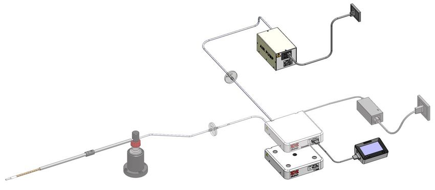
This page was left blank

Index
1    PREFACE ..................................................................................................................................................................................... 1
2    SYMBOL DESCRIPTION .......................................................................................................................................................... 2
         SYMBOLS USED IN THIS MANUAL ...............................................................................................................................................................2
         SYMBOLS ON THE PRODUCT LABEL ...........................................................................................................................................................2
3    SAFETY NOTES .......................................................................................................................................................................... 3
4    SUPPLIED EQUIPMENT .......................................................................................................................................................... 5
5    EQUIPMENT NOT SUPPLIED ................................................................................................................................................ 6
         EQUIPMENT REQUIRED ...............................................................................................................................................................................6
         OPTIONAL .....................................................................................................................................................................................................6
6    EQUIPMENT DESCRIPTION .................................................................................................................................................. 7
7    INSTALLATION ......................................................................................................................................................................... 8
         SETTING UP HM-ACTIVE-STANDALONE .........................................................................................................................................8
         HOW TO ASSEMBLE HM-ACTIVE-STANDALONE WITH A BOLD LINE T CONTROLLER .......................................................... 14
8    USER INTERFACE .................................................................................................................................................................. 16
         HOME PAGE ................................................................................................................................................................................................ 16
     8.1.1 How to enter the Setpoint ....................................................................................................................................................... 16
     8.1.2 Controller Status: colours led and meaning .................................................................................................................... 18
         SETTINGS.................................................................................................................................................................................................... 19
     8.2.1 Gas...................................................................................................................................................................................................... 19
         8.2.1.1          Status Page ......................................................................................................................................................................................................... 19
         8.2.1.2          Flowrates ............................................................................................................................................................................................................. 20
     8.2.2         Touch Screen configuration ................................................................................................................................................... 21
         8.2.2.1          Touch Screen Options..................................................................................................................................................................................... 21
         8.2.2.2          Touch Screen Brightness .............................................................................................................................................................................. 21
         8.2.2.3          Touch Screen Visual Effects – icon and glance mode. ...................................................................................................................... 22
         8.2.2.4          Date & Time........................................................................................................................................................................................................ 22
         8.2.2.5          Alarms................................................................................................................................................................................................................... 23
         8.2.2.6          Data Logging ..................................................................................................................................................................................................... 24
       OVERVIEW.................................................................................................................................................................................................. 28
       ICON AND GLANCE MODE VIEW ............................................................................................................................................................. 29
       INFO PAGE .................................................................................................................................................................................................. 30
9    TOUCH SCREEN CALIBRATION ........................................................................................................................................ 31
10    CLEANING & MAINTENANCE ......................................................................................................................................... 32
11    SUPPORT ............................................................................................................................................................................. 33
12    TECHNICAL SPECIFICATIONS ....................................................................................................................................... 34
13    TROUBLESHOOTING ........................................................................................................................................................ 35
14    FIGURE LIST ........................................................................................................................................................................ 36
15    MANUAL REVISION TABLE ............................................................................................................................................ 37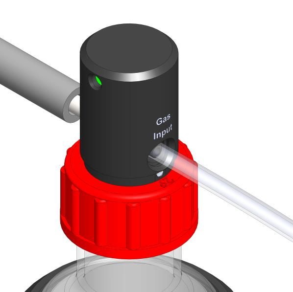
1    Preface

         HM-ACTIVE-STANDALONE is a Digital Humidity Controller that employs a humidity sensor to control the
relative humidity of the gas delivered to the incubation chamber. Relative humidity can be controlled in a range
depending on working temperature. At 37°C relative humidity can be regulated in the range 50% to 95%.
         HM-ACTIVE-STANDALONE can be supplied with any premixed gas at controlled pressure from tanks or
gas controller. The flow rate can be regulated from 0.0 L/min to 1.0 L/min using the needle valve on the rear panel
of HM-ACTIVE-STANDALONE. HM-ACTIVE-STANDALONE can be used as a stand-alone device as well as in
combination with any kind of microscope incubator or gas controller.
         HM-ACTIVE-STANDALONE consists of a Humidity Control-Unit and Humidity Module that consists of the
Humidity Sensor Lid, the Humidity bottle with its heater (Heated Base) and the Heated and Insulated Tube. The
sensor included in the Humidity Sensor Lid regulates the temperature of the water inside the Humidity Bottle in
order to achieve the desired relative humidity of the gas delivered to the incubation chamber. Deviation from the
desired value of the relative humidity and flow rate is immediately detected and HM-ACTIVE-STANDALONE will
trigger an alarm to alert the user.
         HM-ACTIVE-STANDALONE is operated via OKO-TOUCH touch screen control panel (to be ordered
separately). OKO-TOUCH features on-board memory for data logging and mini-USB port for data download.
         HM-ACTIVE-STANDALONE connects to any Okolab Bold Line T controller. In this case, a single OKO-
TOUCH operates both, the Bold Line T controller and HM-ACTIVE-STANDALONE.
         HM-ACTIVE-STANDALONE is also compatible with Okolab manual gas mixer and with Okolab air pump
OKO-AP, which enables to use background air as a convenient alternative to the compressed air.

                                                        1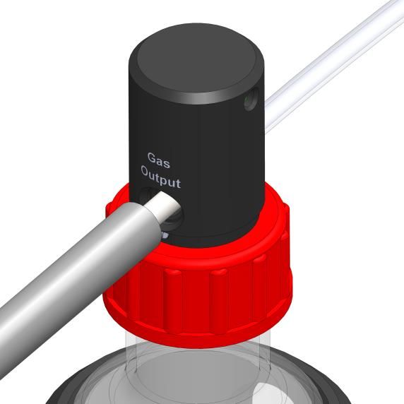
2   Symbol description

      This paragraph describes the symbols used in this manual and on the product label.
     Symbols used in this manual
           The following symbols identify important information to note:

           CAUTION or WARNING: this symbol warns you about the risk of electrical shock.

           CAUTION or WARNING or IMPORTANT: this symbol warns you of circumstances or practices that
           can affect the functionality of the instrument.

      Tip ► Supplies you with helpful suggestions.

      Note ► Supplies you with important information to successfully use the instrument.

     Symbols on the product label

              CE MARKING: this symbol indicates product compliance with EU legislation.

              PRODUCT DISPOSAL: this symbol indicates that this product must not be disposed as urban solid
              waste.

              This symbol indicates the product production date.

              This symbol indicates the Manufacturer data.

              This symbol warns you to read the user manual before starting the device.

              This symbol indicates the protection degree against ingress of solids or liquids inside the product.

IP 30

                                                      2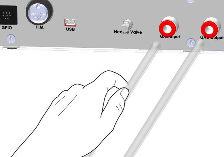
3    Safety Notes

        In order to achieve maximum performance and to ensure proper operation of your new equipment, please
read carefully the following safety notes and the instructions. If you have any question, please contact Okolab.
                −    The equipment must only be used as intended and as described in this Manual.
                −    Equipment should be operated only by technically qualified personnel.
                −    Do not start up the equipment if some of its parts are damaged.
                −    This instrument is not intended for use in locations subject to flammable or explosive gases.
                −    Transport the equipment with care.
                −    Equipment and its internal parts can be damaged by dropping and by shock.
                −    Not following these instructions can result in damage or breakdown of the device and its
                     accessories.
                −    The products labels can be found on the bottom panel of the Main Box.
                −    Do not disassemble any part of the system.
                −    Do not use a volatile solvent such as paint thinner to clean the instrument, because
                     deformation or discoloration may occur.
                −    Use a soft, dry cloth to remove stains from the instrument.
                −    Do not exceed voltage indicated in this manual and on the product label.
                −    Avoid excessive induction noise, static electricity and magnetic fields.
                −    Do not expose this instrument to rain or moisture.
                −    Do NOT go in close contact with or breathe any gas stream whose composition is different
                     from that of ambient air.
                −    Prevent throttling and kinking of tubing.
                −    Check tubing time to time for possible material usage.
                −    Check that all tubing ends are well inserted into the connectors so they cannot slip off
                −    This device is not designed for use for medical applications.
                −    Power cord of unit should be unplugged from electrical outlet when left unused for a long
                     period of time.
                −    VENTILATION. Unit should be situated so that its location or position does not interfere
                     with proper ventilation. Neither the gas mixer nor stream destinations should be in poorly
                     ventilated areas.
                −    Unit should be situated away from heat sources such as open flames, radiators, heat
                     registers, stoves, or other appliances or processes that produce heat.

                −    Do not start up the equipment if the supply cable is damaged.
                −    Connect the equipment only to grounded mains power socket.
                −    Do not disconnect cables while in operation.
                −    Do not open the unit. Do not remove cover or back.
                −    Prevent metal fragments or lead wire scraps from falling inside instrument to avoid electric
                     shock, fire or malfunction.
                −    No user serviceable parts inside.
                −    Unit should never be used where it can fall or be pushed into water.

                                                         3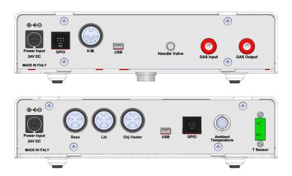
International caution symbol marks this device. It is important to read the “Safety
                          Notes” before installing, using and commissioning this device, as the notes contain
                          important information relating to safety and EMC. Not following these instructions
                          can result in damage or breakdown of the device and its accessories

We reserve the right to make technical variations.

       IN NO EVENT SHALL OKOLAB S.R.L. BE LIABLE FOR ANY DIRECT, INCIDENTAL OR CONSEQUENTIAL
DAMAGES OF ANY NATURE, OR LOSSES OR EXPENSES RESULTING FROM ANY DEFECTIVE PRODUCT OR THE USE
OF ANY PRODUCT.

                                                      4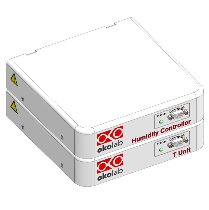
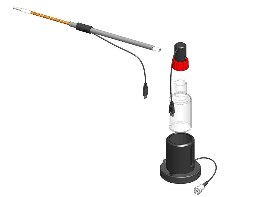
4    Supplied equipment

1.   Humidity Control-Unit, main box.
2.   Humidity Module consists of

     •   Humidity Sensor Lid with Temperature Control
     •   Humidity bottle
     •   Heater Base, heater of the Humidity bottle
     •   Heated and Insulated Tube. Use this tube to connect the Humidity Sensor Lid to your device (or to
         Okolab incubation chamber)

3.   TUBE A (x1). Polyurethane rigid tube 3m long 6mm OD each. Use TUBE A to connect premixed gas supply to
     the corresponding input port labeled “GAS Input” on the rear panel of HM-ACTIVE-STANDALONE.
4.   TUBE C (x1). 2 m long tube that consists of 6 mm OD polyurethane rigid tube with a 4 mm ID silicon tube
     connected and a PTFE filter (0.2 micron porous) in the middle. Use TUBE C to connect “Gas Input” port of
     Humidity Sensor Lid to the output port labeled “GAS Output” on the rear panel of HM-ACTIVE-STANDALONE.
5.   24V-DC Power Adapter (x1).

                                                                            To Premixed
                                                                             gas supply

                                                                                          3

                                                 2                      4                     1   5

 To incubation
   chamber

                                   Figure 1. HM-ACTIVE-STANDALONE – components.

                                                       5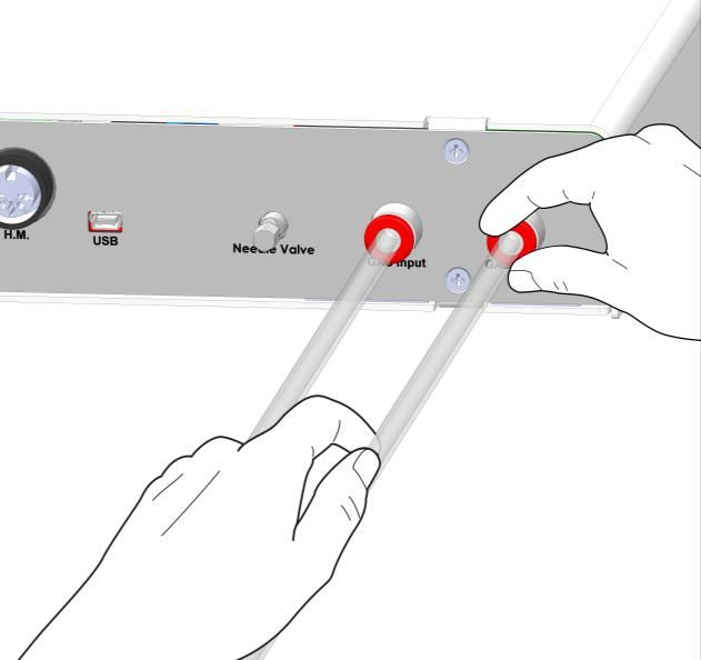
5   Equipment not supplied

        Equipment required

         HM-ACTIVE-STANDALONE is operated via

    •    OKO-TOUCH (to be ordered separately), including:

          −    Touch Screen Interface
          −    #1 RS232 Serial cable. To connect the Touch Screen to the unit.
          −    MINI-USB-OTG cable. To connect a USB pen to the OKO-TOUCH for data download.
        Optional

         HM-ACTIVE-STANDALONE is compatible with:

    •    OKO-AP, including:

          −    TUBE B. 2 m long tube that consists of 6 mm OD polyurethane rigid tube with a 4 mm ID silicon
               tube connected and a hydrophobic filter (0.2 micron porous) in the middle. Use TUBE B to connect
               OKO-AP to the input port labeled “GAS Input” on the rear panel of HM-ACTIVE-STANDALONE.

                                                                       OKO-AP

                                                                                              OKO-TOUCH

                                                                           H301-T-UNIT-BL

                        Figure 2. HM-ACTIVE-STANDALONE within a typical H301 configuration.

         Note ► Order OKO-AP, if you want to humidify ambient airflow.

                                                        6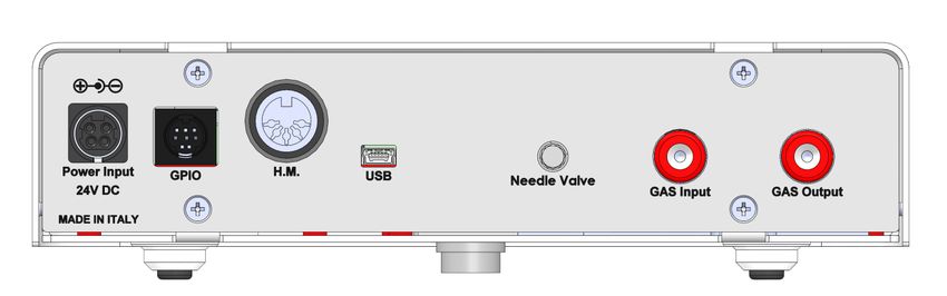
6    Equipment Description

         Figure 3 illustrates HM-ACTIVE-STANDALONE front panel:

1.   Status Led

2.   RS232 connector. Connector for OKO-TOUCH.

                                                                     1        2

                                            Figure 3. Front Panel Overview.

         Figure 4 illustrated HM-ACTIVE-STANDALONE rear panel:

1. Power Input

3.   GPIO (General Purpose Input Output) connector.

4.   Humidity Module connector.

5.   USB connector.

6.   Needle Valve

7.   GAS Input. Push to fit connector for 6 mm OD rigid tubing to supply gas to HM-ACTIVE-STANDALONE

8.   GAS Output. Push to fit connector for 6 mm O.D. rigid tubing to supply gas to Humidity Sensor Lid.

                  1        2          3        4                    5         6             7

                                            Figure 4. Rear Panel Overview.

                                                         7
7 Installation
The following paragraph illustrates how to install and to use HM-ACTIVE-STANDALONE
Setting up HM-ACTIVE-STANDALONE
The following instructions will give you the possibility to install the unit quickly. For safe operation
of the unit it is absolutely necessary to read carefully all the instructions and safety notes.
1. Connect gas supply to the input port labeled “GAS Input” on the rear panel of HM-ACTIVE-STANDALONE by
using TUBE A (see Figure 5). Make sure to push the tube all the way into the push to fit connector thus avoiding
any gas leak.
Figure 5. How to connect tubing to push to ft connector.
To remove tubing from the push to fit connector, push the red rubber ring while pulling the tubing (see
Figure 6).
Figure 6. How to disconnect tubing from push to fit connector.
8Tip ► If the tubing does not come out easily, do not force it, simply make sure the red ring is properly pushed.
Before disconnecting any of tubing connected to HM-ACTIVE-STANDALONE, make sure there is no
residual pressure by adjusting the upstream pressure of the system or the tanks.
.
Figure 7 shows the connection between premixed gas tank and the push to fit connector labeled “GAS Input”
on the rear panel of HM-ACTIVE-STANDALONE.
A
Premixed gas
TUBE A
NOT supplied
Figure 7. Premixed gas tank connection to the rear panel of HM-ACTIVE-STANDALONE.
Note ► If you have ordered OKO-AP, connect TUBE-B between OKO-AP and the input push to fit connector
on the rear panel of HM-ACTIVE-STANDALONE (see Figure 8). Connect OKO-AP to the main power supply.
9B
TUBE B
Figure 8. OKO-AP connection to the rear panel of HM-ACTIVE-STANDALONE.
2. Assemble the components of Humidity Module. Place the Humidity bottle inside the Heater Base. Fill the
Humidity Bottle with distillated water up to few centimeters below the red cap of the Humidity Sensor Lid.
Humidity Sensor
Lid
Heated Tube
Fill the Humidity Bottle
with distilled water
Humidity Bottle
Heated Base
Figure 9. Humidity Module – components.
Tip ► Check regularly the level of the water inside the Humidity Bottle and make sure that it never becomes
empty. The Humidity bottle will become empty after approximately 50-60 hours the filling.
103. Close the Humidity Bottle with the Humidity Sensor Lid and connect the cable of the Humidity Sensor Lid to
the Heater Base. (1 in Figure 10 a) Connect the Heated and Insulted Tube to the port labeled “Gas Output” of
Humidity Sensor Lid (see Figure 10 b) and connect its cable to the Heater Base (see 2 in Figure 10 a).
2 1
a b
Figure 10. Humidity Module assembly (a – b).
4. Use TUBE C to connect the push to fit connector labeled “GAS Output” on the rear panel of HM-ACTIVE-
STANDALONE to the port labeled “Gas Input” on the Humidity Sensor Lid (see Figure 11).
TUBE C
Figure 11. Gas Input connection.
5. Connect Heated and Insulated Tube to your incubation chamber system
11HM-ACTIVE-STANDALONE
C
Heated Tube
TUBE C
Incubation chamber
Figure 12. HM-ACTIVE-STANDALONE – tubing connections.
6. Connect the Heated Based to the port label “H.M.” on the rear panel of HM-ACTIVE-STANDALONE (see Figure
13).
HM-ACTIVE-STANDALONE
Figure 13. Humidity Module connection.
7. Connect OKO-TOUCH to HM-ACTIVE-STANDALONE with the RS232 serial cable as illustrated in Figure 14.
12HM-ACTIVE-STANDALONE
OKO-TOUCH
Figure 14. OKO-TOUCH Connection.
8. Connect the power adapter to HM-ACTIVE-STANDALONE.
9. To switch HM-ACTIVE-STANDALONE on use the power button on OKO-TOUCH.
10. The Status led (1 in Figure 3) on the front panel of HM-ACTIVE-STANDALONE will start blinking.
11. Once the system has been initialized the Status led on the front of HM-ACTIVE-STANDALONE will stop blinking
and will turn steadily on. The Homepage will appear on the touch screen, the color of the Status Indicator (see
1 in Figure 18 and Figure 21) on the tabs will be yellow at the start.
12. Select the Setpoint of the Relative Humidity and of Flow rate from the touch screen Home page (see Paragraph
8.1.1).
Note ►The Flow rate Setpoint selected from the touch screen is a reference value. To set the Flow rate,
regulate manually the needle valve on the rear panel of HM-ACTIVE-STANDALONE.
13. Regulate manually the Flow rate using the needle valve on the rear panel of HM-ACTIVE-STANDALONE. Turn
the needle valve knob (1 in Figure 15) counterclockwise to increase the Flow rate. Set the Flow rate to the
desired value. Then, rotate the O-ring (2 in Figure 15) clockwise until it stops in order to lock the needle
valve.
132 1
Figure 15. Needle valve regulation.
You can read the current value of gas Flow rate on the corresponding tab on the Home page (3 in Figure 18).
Note ►OKO-TOUCH is pre-set at 90% of Relative Humidity and 0.2 L/min of Flow rate.
Note ►If the Flow rate value manually regulated is different from the Setpoint Flow rate, the system will
trigger an alarm.
14. The Status Indicator on the Home page becomes green when the Setpoints are reached and are stable (see 1
in Figure 18 and Figure 21).
How to assemble HM-ACTIVE-STANDALONE with a Bold Line T controller
HM-ACTIVE-STANDALONE can be used as a stand-alone device or in combination with any one of the Bold
Line T controllers. Figure 16 shows how to assemble HM-ACTIVE-STANDALONE for example, with a H301-T UNIT-
BL-PLUS.
a b
Figure 16. HM-ACTIVE-STANDALONE and H301-T-UNIT-BL-PLUS (a – b).
HM-ACTIVE-STANDALONE must stack on top of the Bold Line T controller by lining up the bus ports
located on the top and bottom surface of each unit. When the units are properly connected the temperature,
relative humidity and, flow rate parameters will appear on the Home page of OKO-TOUCH.
14Tip ► If not all the parameters appear on OKO-TOUCH Home Page then the units are not properly connected.
Please check that the bus ports are properly aligned (see Figure 17).
Figure 17. HM-ACTIVE-STANDALONE and H301-T-UNIT-BL PLUS on stock.
158 User Interface
This chapter describes the user interface of HM-ACTIVE-STANDALONE.
Home page
1 2 3
10
9
8
7
6 5 4
Figure 18. Homepage of HM-ACTIVE-STANDALONE Touch Screen Display.
1. Status Indicator.
2. Relative Humidity and Flow rate Setpoint.
3. Relative Humidity and Flow rate current value.
4. USB icon
5. Logging icon
6. Display mode. Touch here to switch display mode.
7. Overview page.
8. Settings. Press here to access system options and settings.
9. Home. To open the homepage.
10. Product info. Press here to know generic info about HM-ACTIVE-STANDALONE and running
time.
Note ►OKO-TOUCH is pre-set at 90% of Relative Humidity and 0.2 L/min of Flow rate.
8.1.1 How to enter the Setpoint
To input a new Relative Humidity Setpoint, touch the corresponding tab, as indicated in Figure 19 a.
161 2
3
a b
Figure 19. How to change the Relative Humidity Setpoint (a – b).
The Setpoint regulation page will appear as in the Figure 19 b. You can modify the Setpoint by clicking on
+ and – for both Humidity and T Chamber Setpoint. Once you have input the Setpoint, press Save (3 in Figure 19
b) to save or Cancel to undo.
To input a new Flow rate Setpoint, touch the corresponding tab, as indicated in Figure 20a.
3
1
2
a
b
Figure 20. How to change the Flow rate value (a – b).
The Total Flow regulation page will appear as in the Figure 20 b. You can modify the Total Flow by clicking
on + and – or tap-drag the slider (3 Figure 20 b). Once you have input the new value, press Save (2 Figure 20 b) to
save or Cancel to undo. If you press on Default the flow rate will be set at 0.2 L/min.
Note ►After any change in the Flow rate from touch screen, regulate manually the Flow rate of the input
gas by using the needle valve on the rear panel of HM-ACTIVE-STANDALONE. If the Flow rate value manually
regulated is different from the Setpoint Flow rate, the system will trigger an alarm.
Note ►After any change in Setpoint value, HM-ACTIVE-STANDALONE enters into a transient regime, the
Status Indicator and the TOP LED (see Figure 21) turn yellow (see paragraph 8.1.2). During the transient
regime, HM-ACTIVE-STANDALONE will not trigger on alarm.
178.1.2 Controller Status: colours led and meaning
HM-ACTIVE-STANDALONE can assume four different status, which are represented by the colors assumed
by the Status Indicator and by the TOP LED (see Figure 21):
The GREEN color indicates that the Setpoint value has been reached (within the
tolerance defined in the alarm subpage, see paragraph 8.2.2.5) and that the system is working
properly.
Controller Status: NORMAL
The YELLOW color indicates that the controller is in transient regime. The Yellow light
will appear after the controller is turned on and after any Setpoint change. The system is working
properly, it is not in alarm and no action is needed. As soon as HM-ACTIVE-STANDALONE reaches
the desired Relative Humidity and Flow Rate, HM-ACTIVE-STANDALONE Status changes to
NORMAL and the color turns GREEN. If HM-ACTIVE-STANDALONE cannot reach the Setpoint
values within the maximum time defined by the user (see paragraph 8.2.2.5), the Status changes
to ALARM and the color turns ORANGE.
Controller Status: TRANSIENT
The ORANGE color indicates that the current Setpoint is not correct and its value is out
of the set tolerance (see alarm subpages in paragraph 8.2.2.5). Most commonly this is related to
gas leaks or gas source(s) running low. Verify that all cables are correctly connected. Check all
tubing for gas leaks and pressure in gas supply tanks.
Controller Status: ALARM
The RED color indicates that there is a problem with the unit itself (for example the
sensor is broken). The system is on alarm. Turn the system off, wait for 5 minutes, and turn it
back on. If the color is still red, contact Okolab for support.
Controller Status: ALARM
Tip ► The TOP LED follows the same color code as the Status Indicator (see Figure 21). To enable/disable
the TOP LED follow the instruction reported in paragraph 8.2.2.3.
Top LED
Status indicator
Figure 21. Status Indicator and TOP LED.
18Settings
8.2.1 Gas
Press on Settings icon to enter the Settings menu, as shown in the Figure 22 a. To enter the Gas
Settings Submenu, press the Gas icon (see Figure 22 b). Then the page shown in Figure 23 appears.
a b
Figure 22. Gas Settings (a – b).
Figure 23. Gas Settings submenu.
8.2.1.1 Status Page
Press the Status icon to enter the status page (see Figure 24 a). The Status page displays a summary
of all parameters. It useful to check that the system is working properly.
19a b
Figure 24. Status page view (a - b).
Note ► The Status page contains advanced technical data. You may be asked to refer to this page during
Okolab assistance session.
8.2.1.2 Flowrates
Press the Flowrates icon to check how many liters per minute of premixed gas the system is consuming
(see Figure 25 a and b). Additionally, this panel allows you to select the Flow rate of the gas mixture you want to
send to your incubator/device. Press + and – or tap-drag the slider to set the Flow rate in the range 0.0 – 1L/min.
in the page that opens (Figure 26).
a b
Figure 25. Flowrates View (a – b).
Figure 26. How to change the total flow rate.
208.2.2 Touch Screen configuration
Press on Settings icon to enter the Settings menu, as shown in the Figure 27 a. To enter the Touch
Screen configuration menu, press on the icon , as shown in Figure 27 b.
a b
Figure 27.Touch screen settings (a – b).
8.2.2.1 Touch Screen Options
Press the Options icon (see Figure 28 a) to enter the Touch Screen Options page. The Display Options
menu allows to set the time frame in which the minimum and maximum Relative Humidity and Flow rate values
are collected.
To insert the time frame, press the + / - icons or scroll the Chart history length bar (1 in Figure 28 b).
Note ► The chart history value length is pre-set at 5 minutes.
Note ► Recommended value for the chart history length is 60 or 120 minutes.
To change the sound frequency press the + / - icons or scroll the Buzzer frequency bar (2 in Figure 28 b),
then press Save (4 in Figure 28 b) to confirm.
Note ► To activate a sound at each touch, flag the Touch Buzzer checkbox (3 in Figure 28 b).
1
2
4
3
a b
Figure 28. Touch Options (a – b).
8.2.2.2 Touch Screen Brightness
Press the icon (see Figure 29 a) and scroll the bar (1 in Figure 29 b) or press the + / - icons in the
page that opens to modify display Brightness. Set the required configuration and press Save (2 in Figure 29 b) to
confirm.
211
2
a b
Figure 29. Brightness display page (a – b).
8.2.2.3 Touch Screen Visual Effects – icon and glance mode.
Press on the icon to enter the Display visual effects menu, see Figure 30 a.
a b
Figure 30. Visual Effects (a – b).
• TOP LED Settings. The TOP LED settings allows you to establish when the TOP LED should be illuminated:
if you select Never, the Top LED will never illuminate, if you select On Alarm, the TOP LED will illuminate
only when HM-ACTIVE-STANDALONE is in Alarm Status (see paragraph 8.1.2), if you select Always, the
TOP LED will always illuminate.
• High Contrast color. The High Contrast color setting defines the colour of the TOP LED and of the digits
displayed in Glance Mode (see paragraph 0 for Glance Mode). If you select White, the TOP LED illuminates
in white colour (according to the criterion selected in TOP LED setting) and the digits displayed in Glance
Mode are white. If you select Dynamic the colour of the TOP LED and the colour of the digits in Glance
Mode follow the colour coding reported in 8.1.2.
Tip ► To swap between Icon and Glance mode press on the icon (see paragraph 8.4).
8.2.2.4 Date & Time
To set Date & Time, follow the instructions below:
1. Press the Date & Time icon (see Figure 31 a).
2. Set the values by using the +/- icons (1 and 2 in Figure 31 b).
Tip ► Flag the 24 hours box, if you want to use the hour format based on 24 hours (3 in Figure 31 b).
223. Click on Save to confirm (4 in Figure 31 b) or Cancel to undo.
2
1
4
3
a b
Figure 31. Touch screen settings. Date and Time (a – b).
8.2.2.5 Alarms
HM-ACTIVE-STANDALONE also allows activating visual and audible alarms.
To set the alarms specifications, press the Alarms icon (see Figure 32 a), then follow the indications
below:
1. Click on the Humidity icon to set the Humidity deviation for a period of time then the system triggers an
alarm.
Tip ►Flag the Buzzer checkbox if you want the Alarm to be acoustical as well rather than just being
displayed.
a b
Figure 32. How to enter in Alarms page (a -b).
2. Insert the Humidity Deviation by scrolling the bar (1 in Figure 33) or pressing the +/- icons.
Note ►The Humidity Deviation value defines the tolerance from the Setpoint.
Note ►The Humidity deviation value range is 5.0-20.0 %.
3. Insert the Humidity Time by scrolling the bar (2 in Figure 33) or pressing the +/- icons.
Note ►The Humidity Time value defines the time for which the Relative Humidity value may remain outside
the allowed tolerance before HM-ACTIVE-STANDALONE triggers an alarm.
Note ►The alarm time range is 5-20 minutes.
4. Press Save (3 in Figure 33) to confirm.
231
2
3
Figure 33. How to set the Deviation and Time Alarm.
In Figure 33 the following settings are displayed as an example (valid only after the system has reached
its stationary state). If the Humidity Deviation from Setpoint is 10% or greater (i.e. if Setpoint Relative Humidity is
80% and the composition reaches a value equal or less than 70% or equal or more than 90%) for a period of time
equal or longer than 15 minutes (Humidity Time set in this example) then the system triggers an Alarm.
Tip ►After any change in the Setpoint value the device enters into a transient regime.
8.2.2.6 Data Logging
HM-ACTIVE-STANDALONE touch screen interface, OKO-TOUCH (see Figure 2), is equipped with on-board
memory for data logging and storage. A simple routine allows downloading data to USB drive or to PC.
In order to log and then download the logged data, connect a USB drive (not supplied) to OKO-TOUCH,
using MINI-USB-OTG cable (provided), as shown in Figure 34.
MINI-USB-OTG
USB Port
USB Drive
OKO-TOUCH
Figure 34. USB drive connection.
To activate the logging, follow the steps indicated below:
1. Press on Settings icon (see Figure 35 a) and press on Touch screen icon on the window that opens
next (see Figure 35 b).
24a b
Figure 35 (a) How to enter the setting menu; (b) how to enter the Touch Screen menu.
2. Press on Logging icon (see Figure 36 a) and flag Internal memory in the page that appears (see Figure 36
b).
Tip ► When activating the logging on the internal memory, you can access the Logging page also by pressing
the activated logging icon on the Homepage, as shown in Figure 37
a b
Figure 36. Logging. (a) How to enter in the logging menu; (b) logging in internal memory.
Figure 37. How to access the Logging page from the Homepage.
3. Press on the icon to insert the Time Interval i.e. the frequency with which you want to record a data point,
as shown in Figure 38. In this example a data point is logged every 30 seconds, you can change Time Interval
in the range 1-60 seconds.
25a b
Figure 38. How to set the logging time (a – b).
4. Choose how you want to organize the data when downloaded, by pressing on Day, Week or Month, see Figure
38 a.
Tip ►If you select Day, the data will be split in files, each one containing the data of one day. If you select
Week, the data will be split in files, each one containing the data of one week.
5. Write the file name suffix to be reported in the downloaded files by pressing on the keyboard icon , see
Figure 39 a.
6. Press Save, see Figure 39 b.
Tip ►With the selections as in Figure 38 and in Figure 39, the data will be downloaded on the USB drive as
shown in Figure 40.
a b
Figure 39. Data Logging. How to define the suffix for the downloaded files (a – b).
Figure 40. Downloaded files on the pen drive.
Note ► If you press on the screwdriver icon (see Figure 41 a) you can view the logging starting date, the
available memory and the latest download, see Figure 41 b.
26Note ►The available memory depends on the time interval you have inserted in the Logging page. The
default logging Time Interval is 30 seconds.
a b
Figure 41. Internal memory status. (a) Logging page settings; (b) Internal log page settings.
To download the data, press on To USB or on Erase if you want to delete the data, see Figure 41 b.
a b
Figure 42. Download to USB.
You can activate the logging also on the USB drive, by flagging on USB drive, see Figure 43 a.
a b
Figure 43. Logging on USB flash drive. (a) USB drive selection; (b) Reminder to connect the USB drive.
In this case, OKO-TOUCH warns you that a USB drive must be connected to the USB port, see Figure 43 b,
and will store the data on the USB drive.
27Figure 44. Logging to USB drive.
Note ► When connecting the USB drive to OKO-TOUCH, a USB drive icon appears on the Homepage. If
you activate the logging on USB drive, a red dot appears on the USB drive, to remind that the USB drive should
not be disconnected while data logging is ongoing see Figure 44.
Overview
Press on the icon to open the Overview page as show in Figure 45 a.
a b
Figure 45. Overview Status page. (a) How to enter in the Overview Page (b) Overview Status Page.
Note ► This page contains advanced technical data. You may be asked to refer to this page during Okolab
assistance session.
By pressing the area representing the Humidity Module (see Figure 46 a), the Humidifier Status/Settings
page will appear (see Figure 46 b).
28a b
Figure 46. Humidify Overview page.
The Relative Humidity Setpoint can be change also pressing on the drop in the incubating chamber (see
Figure 46 b). Click on Total Flow area to change the Flow rate value (see Figure 47).
Figure 47. Flow Rate Setpoint from Overview page.
Note ► If you have HM-ACTIVE-STANDALONE in stack with a Temperature Unit or with a Gas Controller, in
the Overview you will find the Humidity and the Temperature (or Gas) Controllers variables. Figure 48 shows
an example of combined system Overview, H301-T-UNIT-BL and HM-ACTIVE-STANDALONE.
Figure 48. HM-ACTIVE-STANDALONE and H301-T-UNIT-BL-PLUS Overview.
Icon and Glance Mode View
HM-ACTIVE-STANDALONE features two display modalities: Icon mode and Glance Mode, as shown in
Figure 49 a and b. You can swap between the two display modalities by pressing on icon .
29a b
Figure 49. Display modalities. (a) Icon Mode; (b) Glance Mode.
Info page
Press the icon to access the Info Page, as shown in Figure 50. This page contains the information
related to the OKO-TOUCH (as shown in Figure 51 a) and to HM-ACTIVE-STANDALONE version (as shown in
Figure 51 b).
Figure 50. Info page selection.
a b
Figure 51. Info page OKO-TOUCH (a) and HM-ACTIVE-STANDALONE (b).
Tip ►Please have this information handy when contacting Okolab for support
309 Touch Screen Calibration
Keep pressed the ON/OFF button on OKO-TOUCH for 7 seconds to start the Touch Screen Calibration (see
Figure 52). While holding the button, the pop-up message shown in Figure 53 a appears. Then tap blue calibration
dots until the calibration is completed (see Figure 53 b).
Figure 52. How to enter in Touch Screen Calibration.
a b
Figure 53. Start Touch Screen Calibration (a – b).
3110 Cleaning & Maintenance
Cleaning
Please, follow the instructions below to clean HM-ACTIVE-STANDALONE
− Use a polishing cloth or dry cloth to wipe off dust and dirt.
− Before cleaning the unit, pull out the main plug.
− Liquids should not be entered inside HM-ACTIVE-STANDALONE
Maintenance
− Verify periodically the status of all hoses/tubing. If some hoses/tubing is damaged, contact Okolab to
receive assistance.
− After 2 years, disconnect all polyurethane tubing, cut the last 1 cm of the tubing and reconnect them.
How to clean inside the Humidity Sensor Lid
− Okolab Air pumps have to be replaced every 18-24 months.
3211 Support
To contact one of our engineers please write to support@oko-lab.com or contact us through the live chat
in www.oko-lab.com. You can request a remote support session anytime.
Please, do not hesitate to contact Okolab should you need any further commercial information or technical
support.
For HARDWARE SUPPORT: sibillo@oko-lab.com
Phone +39 081 806 3470
Fax: +39 081 876 4410
Mobile: +39 348 96807 18
For COMMERCIAL SUPPORT WORLDWIDE: lanzaro@oko-lab.com
Phone +39 081 806 2624
Fax: +39 081 876 4410
Mobile: +39 348 96807 17
For COMMERCIAL SUPPORT US&CANADA: foppiano@oko-lab.com
For COMMERCIAL SUPPORT CHINA: tong@oko-lab.cn
3312 Technical Specifications
HM-ACTIVE-STANDALONE – Technical Specifications
Range: 51-95% @37°C
Humidity Step size: 1%
Accuracy: 1%
Range: 0-1.0 l/min
Flow
Step size: 0.1 l/min
Input Gas pressure 0.5 barg
Gas output maximum flow rate 1.0 L/min
Operating Temperature 0°C ~ +55°C
Storage Temperature -5°C ~ +60°C
Operating Humidity 0-70%
Power Consumption Input 24V-DC 66W Max
Weight 1.5 Kg
Table 1. Technical specifications.
3413 Troubleshooting
We have collected in the table below some frequently asked questions, please contact Okolab if you need
support.
Symptom Probable cause Remedy
Power cord disconnected Properly connect the cable
Device off
Power cord damaged Substitute the cable
Connect the Heated Base to HM-ACTIVE-
No humidity displayed or “nan" Heated Base disconnected
STANDALONE
Check the gas source (Open the tank or
The gas source is closed or the
switch on the Gas Controller or the Air
tank is close to the end
Pump)
No flow rate displayed Premixed gas flow tubing
Connect the premixed gas flow tubing
disconnected
Flow sensor damaged Contact Okolab to receive assistance
Flow sensor damaged Contact Okolab to receive assistance
Flow rate “nan”
The little led on the front of the Humidity
OKO-TOUCH broken Contact Okolab to receive assistance
Controller is green but the OKO-TOUCH is
off
Heated Base cable disconnected Connect the cable
Heated Base damaged Contact Okolab to receive assistance
Heated Base cold
Heated Base and/or cable
Contact Okolab to receive assistance
damaged
Fill it with distilled water until to a couple
Humidifying Module empty
of centimeters below the red cap.
Fast sample drying Correctly connect the heater of the
Humidifying Module not heated
Humidifying Module
Heating devices cables Check the cables connection on the rear
Humidity value at 100% for more than two disconnected panel of HM-ACTIVE-STANDALONE
hours Humidity sensor broken Contact Okolab to receive assistance
Check the gas supply and the cables
The current Humidity value is
connection on the rear panel of HM-
far from set point
ACTIVE-STANDALONE
Acoustical alarm sounds Check the gas source and check if you
The current Flow value is far regulated the flowrate properly by the
from set points needle vale on the rear panel of HM-
ACTIVE-STANDALONE
Strongly push the tube into the push to fit
Gas leak on the rear panel of HM-ACTIVE- Not properly inserted tubes
connector.
STANDALONE
Table 2. Troubleshooting table
3514 Figure List
Figure 1. HM-ACTIVE-STANDALONE – components. ..........................................................................................................................................................5
Figure 2. HM-ACTIVE-STANDALONE within a typical H301 configuration..............................................................................................................6
Figure 3. Front Panel Overview. .....................................................................................................................................................................................................7
Figure 4. Rear Panel Overview........................................................................................................................................................................................................7
Figure 5. How to connect tubing to push to ft connector...................................................................................................................................................8
Figure 6. How to disconnect tubing from push to fit connector. ....................................................................................................................................8
Figure 7. Premixed gas tank connection to the rear panel of HM-ACTIVE-STANDALONE. ..............................................................................9
Figure 8. OKO-AP connection to the rear panel of HM-ACTIVE-STANDALONE................................................................................................... 10
Figure 9. Humidity Module – components. ............................................................................................................................................................................ 10
Figure 10. Humidity Module assembly (a – b). .................................................................................................................................................................... 11
Figure 11. Gas Input connection. ................................................................................................................................................................................................ 11
Figure 12. HM-ACTIVE-STANDALONE – tubing connections. ...................................................................................................................................... 12
Figure 13. Humidity Module connection. ............................................................................................................................................................................... 12
Figure 14. OKO-TOUCH Connection. ......................................................................................................................................................................................... 13
Figure 15. Needle valve regulation. ........................................................................................................................................................................................... 14
Figure 16. HM-ACTIVE-STANDALONE and H301-T-UNIT-BL-PLUS (a – b). ......................................................................................................... 14
Figure 17. HM-ACTIVE-STANDALONE and H301-T-UNIT-BL PLUS on stock. ..................................................................................................... 15
Figure 18. Homepage of HM-ACTIVE-STANDALONE Touch Screen Display. ....................................................................................................... 16
Figure 19. How to change the Relative Humidity Setpoint (a – b). ............................................................................................................................ 17
Figure 20. How to change the Flow rate value (a – b). ..................................................................................................................................................... 17
Figure 21. Status Indicator and TOP LED. .............................................................................................................................................................................. 18
Figure 22. Gas Settings (a – b). ..................................................................................................................................................................................................... 19
Figure 23. Gas Settings submenu. ............................................................................................................................................................................................... 19
Figure 24. Status page view (a - b). ............................................................................................................................................................................................ 20
Figure 25. Flowrates View (a – b). ............................................................................................................................................................................................. 20
Figure 26. How to change the total flow rate. ....................................................................................................................................................................... 20
Figure 27.Touch screen settings (a – b). ................................................................................................................................................................................. 21
Figure 28. Touch Options (a – b). ............................................................................................................................................................................................... 21
Figure 29. Brightness display page (a – b). ............................................................................................................................................................................ 22
Figure 30. Visual Effects (a – b). .................................................................................................................................................................................................. 22
Figure 31. Touch screen settings. Date and Time (a – b). ............................................................................................................................................... 23
Figure 32. How to enter in Alarms page (a -b). .................................................................................................................................................................... 23
Figure 33. How to set the Deviation and Time Alarm....................................................................................................................................................... 24
Figure 34. USB drive connection. ................................................................................................................................................................................................ 24
Figure 35 (a) How to enter the setting menu; (b) how to enter the Touch Screen menu. .............................................................................. 25
Figure 36. Logging. (a) How to enter in the logging menu; (b) logging in internal memory. ........................................................................ 25
Figure 37. How to access the Logging page from the Homepage. ............................................................................................................................... 25
Figure 38. How to set the logging time (a – b). .................................................................................................................................................................... 26
Figure 39. Data Logging. How to define the suffix for the downloaded files (a – b). ......................................................................................... 26
Figure 40. Downloaded files on the pen drive. .................................................................................................................................................................... 26
Figure 41. Internal memory status. (a) Logging page settings; (b) Internal log page settings. .................................................................... 27
Figure 42. Download to USB. ........................................................................................................................................................................................................ 27
Figure 43. Logging on USB flash drive. (a) USB drive selection; (b) Reminder to connect the USB drive. ............................................. 27
Figure 44. Logging to USB drive. ................................................................................................................................................................................................. 28
Figure 45. Overview Status page. (a) How to enter in the Overview Page (b) Overview Status Page. ..................................................... 28
Figure 46. Humidify Overview page. ......................................................................................................................................................................................... 29
Figure 47. Flow Rate Setpoint from Overview page. ......................................................................................................................................................... 29
Figure 48. HM-ACTIVE-STANDALONE and H301-T-UNIT-BL-PLUS Overview. .................................................................................................. 29
Figure 49. Display modalities. (a) Icon Mode; (b) Glance Mode. ................................................................................................................................. 30
Figure 50. Info page selection. ..................................................................................................................................................................................................... 30
Figure 51. Info page OKO-TOUCH (a) and HM-ACTIVE-STANDALONE (b). .......................................................................................................... 30
Figure 52. How to enter in Touch Screen Calibration. ..................................................................................................................................................... 31
Figure 53. Start Touch Screen Calibration (a – b). ............................................................................................................................................................. 31
3615 Manual Revision Table
Revision Number Additions or changes Date
01 Edit new form factor User Manual August 2019
02 Cleaning & Maintenance January 2020
37WARRANTY
Okolab S.r.l. warrants “HM-ACTIVE-STANDALONE” to be free of defects in materials and workmanship for
a period of one year starting from invoice date. If the unit malfunctions, it must be returned to the factory for
evaluation. If the equipment has to be returned to the factory, please ensure that is carefully and properly packed.
Okolab S.r.l. accepts no responsibility for damage due to unsatisfactory packing. If the unit is found to be defective,
it will be repaired or replaced at no charge. This warranty does not apply to defects resulting from any actions of
the purchaser. Components which wear are not warranted. Okolab S.r.l. neither assumes responsibility for any
omissions or errors nor assumes liability for any damage that may results from improper use of its products in
accordance with information provided by Okolab S.r.l. Okolab S.r.l. warrants only the parts manufactured by
Okolab S.r.l to be free of defects. Okolab S.r.l. makes no other warranties or representations of any kind whatsoever,
express or implied, except that of title, and all implied warranties including any warranty of merchantability and
fitness for a particular purpose are hereby disclaimed. LIMITATION OF LIABILITY: the total liability of Okolab S.r.l.
shall not exceed the purchase price of the component upon which liability is based. In NO event shall Okolab S.r.l.
be liable for consequential, incidental or special damage.
IST1239_REV01
SV 2.1.3.3038
38You can also read