Mars Workstation
User Manual
←
→
Page content transcription
If your browser does not render page correctly, please read the page content below
Mars Workstation User Manual
Version 2.1: February 10, 2014
INDEX

How To Use This Manual .............................................................................................................................................5
Introduction ...................................................................................................................................................................6
SAFETY INSTRUCTIONS ............................................................................................................................................7
   Before operation of the workstation ..........................................................................................................................7
INSTALLATION ............................................................................................................................................................8
   Device Placement .....................................................................................................................................................8
AIR FLOW WORKING PRINCIPLE ..............................................................................................................................9
CONTROL PANEL .....................................................................................................................................................10
GENERAL OPERATING PROCEDURES ..................................................................................................................11
   Connecting the power cord .....................................................................................................................................11
   Switching the Fans ON / OFF at Normal Speed ....................................................................................................11
   Switching the Fans ON / OFF at Reduced Speed ..................................................................................................11
   Alarm .......................................................................................................................................................................11
   Internal Light............................................................................................................................................................12
   UV Light...................................................................................................................................................................12
   Working Heated Surface and ORIGIO Light Source...............................................................................................12
CONTROL & PROGRAMMING ..................................................................................................................................13
   Overview of the Control Panel Menu ......................................................................................................................14
   General air flow information & counter ....................................................................................................................14
   Adjusting the level intensity of the internal light ......................................................................................................15
   Programming and Controlling the UV light timer .....................................................................................................15
      UV Autostart Option Selected: “TODAY” .............................................................................................................16
      UV Autostart Option Selected: “AUTO” ...............................................................................................................17
   Programming Time and Date .................................................................................................................................18
      Option selected: TODAY .....................................................................................................................................19
      Option selected: AUTO........................................................................................................................................20
   Display Mode Functions ..........................................................................................................................................21
HEATED SURFACE ...................................................................................................................................................23
   Operational Characteristics .....................................................................................................................................23
   Temperature Controller ...........................................................................................................................................23
   User Setup ..............................................................................................................................................................25
      Accessing the parameters and information menu ...............................................................................................25
      Resetting the THI and TLO recordings ................................................................................................................25
      Changing channel 1 set point ..............................................................................................................................25
      Standby................................................................................................................................................................26
      Keypad lock .........................................................................................................................................................26
   Operating the heated areas ....................................................................................................................................26
      Normal Operation ................................................................................................................................................26
      Checking the temperature ...................................................................................................................................26

                                                                Version 2.1: February 10, 2014                                                                                  3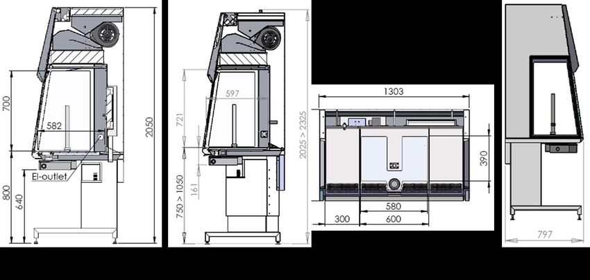
TROUBLESHOOTING Your Workstation ...................................................................................................................27
    Flow 1 alarm ............................................................................................................................................................27
TECHNICAL SPECIFICATIONS ................................................................................................................................31
    MARS 900 IVF or LAF ............................................................................................................................................31
    MARS 1200 IVF or LAF ..........................................................................................................................................32
    MARS 1500 IVF or LAF ..........................................................................................................................................33
    MARS 1800 IVF or LAF ..........................................................................................................................................34
    MARS 1800 Dual ....................................................................................................................................................35
    MARS 1800MP / ICSI .............................................................................................................................................36
SPARE PARTS ...........................................................................................................................................................37
OPERATING THE MICROSCOPE LIGHT SOURCE.................................................................................................38
    ORIGIO Halogen Light Source Model TLB 4000 ....................................................................................................38
       Operating the light source ...................................................................................................................................38
       Replacing the light bulb .......................................................................................................................................39
    ORIGIO LED Light Source Model TLB 7000 ..........................................................................................................40
OPERATING THE STEROMICROSCOPE HEATED GLASS STAGE – HG37 Model ..............................................41
WARRANTY AND LIABILITY .....................................................................................................................................43
    Limited Warranty .....................................................................................................................................................43
    Liability: ...................................................................................................................................................................43
    Replacement ...........................................................................................................................................................43

4                                                                 Version 2.1: February 10, 2014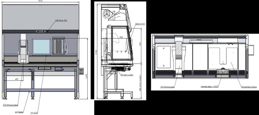
HOW TO USE THIS MANUAL
Warning, Cautions and important Notes

Throughout this manual, blocks of text may be accompanied with a pictogram. These blocks are WARNINGS,
CAUTIONS, and IMPORTANT NOTES and they are used as follows:

Symbols used in this Manual:

                                                        NOTE
                                                        Used to direct attention to a special item.

                                                        WARNING

                                                        DANGER
                                                        UV light radiation hazard. Use only with shielding in
                                                        place. Protect eyes and skin from exposure to UV light.

                                                        FURHTER INFORMATION
                                                        Further information is provided in other sections or
                                                        manuals.

                                        Version 2.1: February 10, 2014                                            5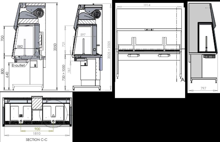
INTRODUCTION
You are now in possession of a high quality microprocessor-controlled Mars IVF Class II Clean Air workstation and
it is designed to provide:
Protection of the processed product against particle /microbiological contamination
Heating control of the heated work area for sample handling
Gassing and Humidification control (Optional)
Heating control of the light opening for morphology study under microscopy (Optional)
This user manual covers the following models:
MARS IVF Clean Air 900
MARS IVF Clean Air 1200
MARS IVF Clean Air 1500
MARS IVF Clean Air 1800
MARS IVF Clean Air 1800 Dual
MARS IVF Clean Air 1800 MP
The MARS IVF Clean Air cabinet has a built-in microprocessor controller featuring:
LCD display indicating fan and alarm status.
Air velocity sensors
Clock (7 days) and hour-counter.
Pre-setting of automatic start-up and UV timer.
Alarm for any deviation from safety conditions.
Furthermore, the MARS IVF Clean Air workstation has the following characteristics:
An ergonomically correct 10° sloping front for maximum operator comfort.
Electrical front window, leaving a work opening of 30 cm.
Side windows in safety glass for perfect light conditions and view to the surroundings.
Negative pressure plenum for highest operator and sample safety.
Adjustable fan speeds.
Work chamber with tabletop in stainless steel (AISI 304).
The internal light is installed between the air distributor and the main filter. This secures that the light is
glare-free and the airflow is turbulence free.
6 Version 2.1: February 10, 2014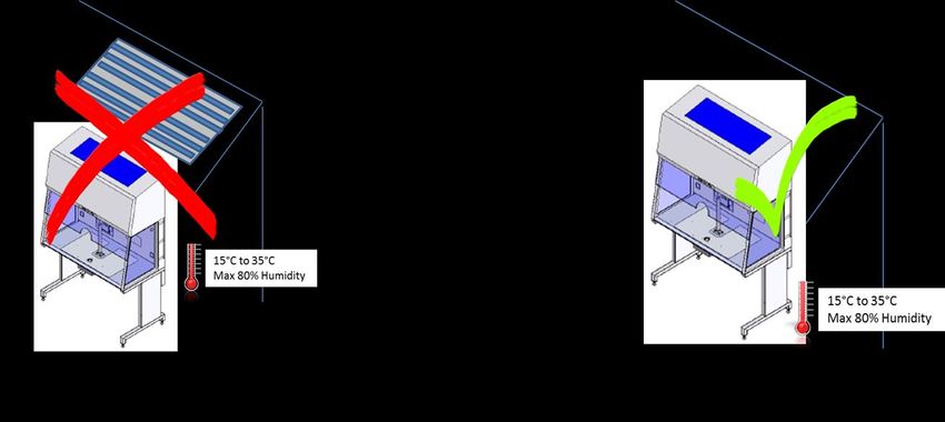
SAFETY INSTRUCTIONS
                              To avoid unintended or improper operation of the workstation, please read
                              this manual carefully

Before operation of the workstation
Before operating your workstation, please note the following:

                 The work chamber is to be carefully cleaned and/or disinfected. Use only hydrogen peroxide
                 (H2O2 Solutions) or products suitable to be used in an IVF lab. NEVER use ammonia or
                 chlorinated cleaners. It is recommended to use special lint-free wipes.
                 To ensure that the working area is clean and sterile the workstation fan must be run at normal
                 speed for at least 30 minutes prior to working inside the Workstation.
                 Objects and instruments must be carefully cleaned and/or disinfected before bringing them into
                 the work chamber.
                 Necessary instruments for use during work must be placed within reach to avoid unnecessary
                 movement inside the Workstation.
                 For reliable operation it is important that the air-flow conditions are as unobstructed as much as
                 possible. Therefore, never overload the work chamber.
                 Put on necessary personal clothing for reducing particle emission from operator (i.e. gloves,
                 masks and general clean room clothing). Special attention should be given to hands and lower
                 parts of the arms, as these are the parts of the operator most likely to emit particles near the
                 product.
                 All work in the workstation must be performed with slow movements. Rapid arm movements in
                 the chamber may cause slipstreams, which will draw contaminated air into the work chamber.
                 Transport of possibly contaminated material may create airflows which can contaminate the
                 product.
                 The safety cabinet must not be used for working with materials which can cause allergic
                 reactions, or any harm to the health of the operator or the personnel. Attention is drawn to the
                 risk assessment requirements of the Control of Substances Hazardous to Health (COSHH)
                 Regulations 1999. (UK)
                 The cabinet is not suitable for HIGH-RISK biological agents. HIGH RISK biological agents
                 include all etiologic agents designated Class 4 by CDC, and oncogenic viruses classed high risk
                 by NCI. (USA)
                 Never operate the workstation cabinet if the fan compartment cover is removed. If this cover is
                 removed, the cabinet will give no protection of the operator or the environment and the fan will
                 run with openly rotating blades.
                 The workstation will not provide any protection for operator or environment against harmful
                 gases or vapors.

                                          Version 2.1: February 10, 2014                                              7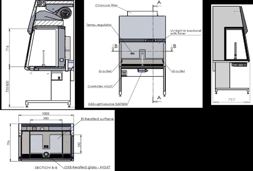
INSTALLATION

                              Please see the installation manual

Device Placement
The device should be placed on a level secure surface, away from heaters, coolers and air-conditioning outlets.

The device may only be operated at temperatures ranging between 15 °C and 35°C, with a maximum 80% relative
humidity, and at normal air pressure.

8                                         Version 2.1: February 10, 2014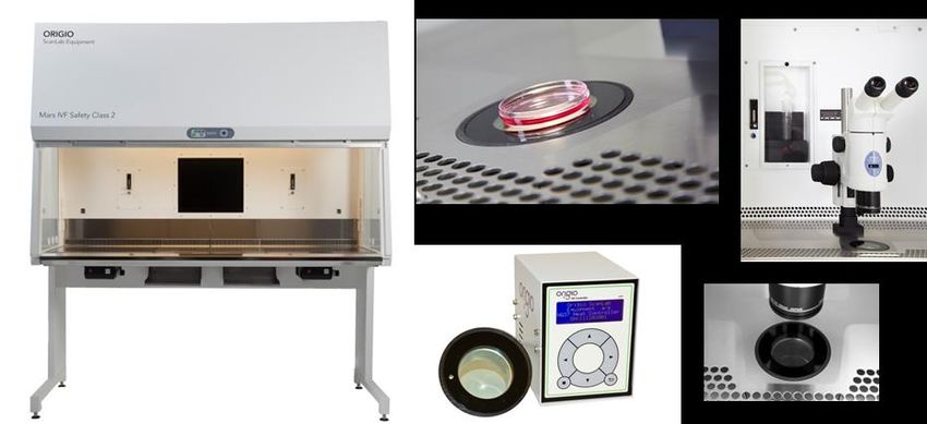
AIR FLOW WORKING PRINCIPLE
                The vertical clean air cabinet is a turbulence-free (laminar) vertical displacement flow of
                clean air in the work chamber protecting the product against particle contamination.

                Filters: The MARS IVF Clean Air workstation main filter is a high-efficiency HEPA filter
                class (H14) and the pre-filter of FORTUNA is EU-3 type to capture dust particles for
                increased life tile of the HEPA filter.

                Air velocity monitoring: The turbulence-free vertical flow can be monitored by means
                of an air velocity sensor. Any deviation from safe conditions will be indicated visually
                and acoustically.

                               Version 2.1: February 10, 2014                                            9
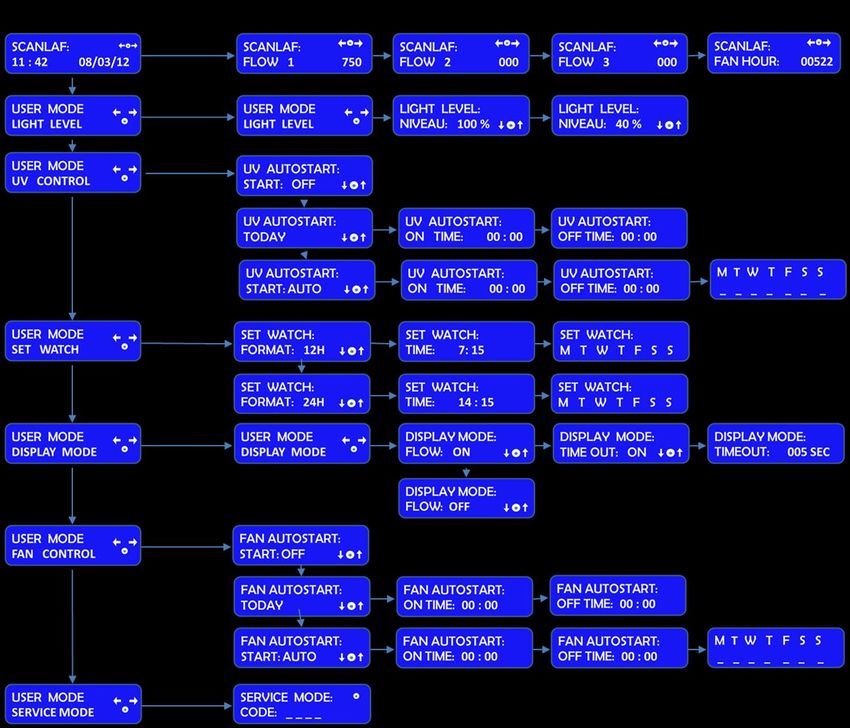
CONTROL PANEL

During normal use, the LED display shows the time and the day and the “Control and programming keys”
to navigate through the menu program. The numbers 0 to 9 in the control and programming keys are for
programming purposes.

10                                  Version 2.1: February 10, 2014
GENERAL OPERATING PROCEDURES
Connecting the power cord
                                                Connect the power cord to the mains power inlet. The power inlet
                                                is located at the back of the workstation. The power outlet must
                                                be grounded.

                                                As soon as the device is connected an audible alarm will be
                                                activated, an LED light will turn on and a message with POWER
                                                UP ERROR will be activated on the control panel.

                                                Press the “enter” button to switch off the alarm and to return to
                                                safe mode.

                            Please see the installation manual for further information.

Switching the Fans ON / OFF at Normal Speed

              Press the “1- Fan Velocity” button to turn the fans ON. When activated a small green light on top
              of the button will switch on.

              Press the “1- Fan Velocity Button” to turn the fans OFF. When activated the small light on top of
              the button will be OFF.

                            To prevent any accidental switching on or off of the fan, the buttons for normal and
                            reduced velocity must be activated for at least 15 seconds before they take effect.

                            DO NOT WORK IN THE WORK SPACE AREA WHEN THE FANS ARE
                            SWITCHED OFF

Switching the Fans ON / OFF at Reduced Speed

              Press the “2- Fan Reduced Velocity” button to turn the fans ON. When activated a small blue
              light on top of the button will switch on.

              Press the “2- Fan Velocity Reduced Button” to turn the fans OFF. When activated the small light
              on top of the button will be OFF.

                            When turning ON the reduced speed velocity, the internal light will turn off to alert
                            the user. The internal light can be switched on again if needed.

Alarm

              When an alarm is activated an audible acoustic signal is activated. On the control panel a small
              red light is activated on the Alarm button. Press the Alarm Button to mute the acoustic alarm
              signal.

              The error causing the alarm will be explained on the LED display.

                                        Version 2.1: February 10, 2014                                              11
When the error has been fixed the audible alarm and the small red light are switched off.
MUTING THE ACOUSTIC SIGNAL WILL NOT SOLVE THE PROBLEM THAT
CAUSED THE ERROR
Internal Light
To switch ON the illumination light of the work chamber, press the “4-Internal Light” button.
When activated, a small blue light on top of the button will switch on.
To switch OFF the illumination light of the work chamber, press the “4-Internal Light” button
again. The small light on top of the button will be OFF.
To adjust the light intensity, refer to the section “Adjusting the level intensity
of the internal light”.
UV Light
The UV light and UV light timer are optional features.
For increased safety against unintended UV radiation which will harm eyes
and skin, use the timer to start the UV decontamination when no personnel is
present in the room where the workstation is located. Use the front shield
cover (Optional) to contain the radiation
To program the UV light time, refer to the section “Programming and Controlling the
UV light timer”.
To switch OFF the illumination light of the work chamber, press the “4-Internal Light” button
again. The small light on top of the button will be OFF.
To switch ON the UV light for decontaminating the work chamber, press the “5- UV Light” button.
When activated a small yellow light on top of the button will switch on
Working Heated Surface and ORIGIO Light Source
To operate the heated work area, refer to the section “Heated Surface”.
To switch ON the ORIGIO Light Source and the working heated surface (s), press the button.
When activated a small blue light on top of the button will switch on. This button simultaneously
activates the working heated surface and the ORIGIO light source. (Note this feature is not
available on the FORTUNA ICSI models)
To switch OFF the ORIGIO Light Source and the working heated surface (s), press the button
again. The small light on top of the button will be switched OFF.
12 Version 2.1: February 10, 2014CONTROL & PROGRAMMING
This section describes how to access the different menus and how to control and to program some the features
offered with your workstation. The Control & Programming menu of your workstation contains the following:
Standard display
Adjusting the intensity of the internal light
Programming and controlling the UV light timer
Setting the internal clock
Adjusting display settings
Programming and controlling the automatic start and shut-off of the fan
Entering the service mode
Version 2.1: February 10, 2014 13Overview of the Control Panel Menu
General air flow information & counter
This section describes how to access information about the running hours of the fan. Depending on the
configuration of the workstation, there can be up to three fans, designated FLOW 1, FLOW 2 and FLOW3.
To learn how to enable and disable these functions refer to the section
“Programming the Air Flow to Auto Start”.
Standard display.
14 Version 2.1: February 10, 2014Press the right or left arrow button to navigate towards the FLOW information.
SCANLAF with FLOW 1 will be displayed together with a value. This value is for
internal service information.
Press the right or left arrow button to navigate towards the FLOW information.
SCANLAF with FLOW 2 will be displayed together with a value. This value is for
internal service information.
Press the right or left arrow button to navigate towards the FLOW information.
SCANLAF with FLOW 3 will be displayed together with a value. This value is for
internal service information.
Press the right or left arrow button to navigate towards the FLOW information.
SCANLAF with FAN HOUR will be displayed together with a value. This value is
the number of hours the fan has been running.
Adjusting the level intensity of the internal light
This section covers how to adjust the light intensity of the internal light of the workstation.
Standard display.
Press the “enter” button to enter the menu.
The USER MODE with the “LIGHT LEVEL” will be displayed together with a
representation of the “Control & Programming Keys”. The first line with the arrow
symbol “ ”enables the user to go back to the previous menu or to move to
another function. The symbol “o” represents the “ENTER” button.
Press the “enter” button to validate your choice.
The LIGHT LEVEL and “NIVEAU: 100 % will be displayed together with a
representation of the Control & Programming Keys
Press on the up or down arrow. The level of intensity will go up or down. Repeat
pressing on the arrow until you reach the level of intensity desired. If you hold
down the arrow, the light intensity will change more rapidly.
Press on the “enter” button to validate and to return to the MENU or wait a few
seconds and the display will return by itself to the standard display
Programming and Controlling the UV light timer
This section describes how to program the UV light timer.
Version 2.1: February 10, 2014 15Note: for this feature to work correctly, you must set up the date and time first. How
to do this is described in the section “Programming Time and Date”
For protection against unintended UV radiation which will harm eyes and
skin, use the timer to start the UV decontamination when no personnel is
present in the room where the workstation is located. Use the front shield
cover (optional) to contain the radiation.
Standard display.
Press the “enter” button to enter the menu.
Press on the right arrow button to enter the next menu.
The USER MODE with the “UV CONTROL” will be displayed together with a
representation of the “Control & Programming Keys. The first line with the arrows
symbol “ ”enables the user to go back to the previous menu or to move to
another function. The symbol “o” represents the “enter” button.
Press the “enter” button to validate your choice.
The UV AUTOSTART with START: OFF will be displayed.
Press the up or down arrow to change the settings between START: OFF, TODAY
and START: AUTO.
If you wish to program the UV light to start today, use UV AUTOSTART TODAY.
If you wish to program the UV light to start on a different day, use UV
AUTOSTART START: AUTO.
UV Autostart Option Selected: “TODAY”
Press the “enter” button to enter the menu.
The UV AUTOSTART and “ON TIME: 00:00” will be displayed. This is the time at
which the UV light should start
Press the “enter” button to validate your choice.
The first digit of the hour will be blinking. To enter the hour press the appropriate
number found on the control panel. Continue this operation for the hours and the
minutes. This will indicate the Time when the UV Light will switch ON
automatically
Press the “enter” button to validate your choice.
16 Version 2.1: February 10, 2014The UV AUTOSTART and “OFF TIME: 00:00” will be displayed. This is the Time
at which the UV Light will switch off.
Press the “enter” button to validate your choice.
The first digit of the hour will be blinking. To enter the hour press the appropriate
number found on the control panel. Continue this operation for the hours and the
minutes. This will indicate the time when the UV light will turn OFF automatically.
Press the “enter” button to validate your choice.
UV Autostart Option Selected: “AUTO”
Note: for this feature to work correctly, you must set up the date and time first. How
to do this is described in the section “Programming Time and Date”
Press the “enter” button to enter the menu.
The UV AUTOSTART and “ON TIME: 00:00” will be displayed. This is the time at
which the UV light should start
Press the “enter” button to validate your choice.
The first digit of the hour will be blinking. To enter the hour press the appropriate
number found on the control panel. Continue this operation for the hours and the
minutes. This will indicate the time when the UV Light will switch ON automatically
Press the “enter” button to validate your choice.
The UV AUTOSTART and “OFF TIME: 00:00” will be displayed. This is the Time
at which the UV Light will switch off.
Press the “enter” button to validate your choice.
The first digit of the hour will be blinking. To enter the hour press the appropriate
number found on the control panel. Continue this operation for the hours and the
minutes. This will indicate the time when the UV light will turn OFF automatically.
Press the “enter” button to validate your choice.
The Week display will appear “ M T W T F S S”
Press the “enter” button to validate your choice.
The Monday option will be blinking.
Version 2.1: February 10, 2014 17Press on the UP arrow to select Monday or press the right and left arrows to
navigate between the days,
In this example the Monday option will be marked with an “X” to indicate that the
UV light will be ON, on Monday at the desired time and will be switched OFF at
the desired time programmed earlier in this section.
Press on the “enter” button to confirm
Programming Time and Date
This section describes how to set the time and the date.
Press the “enter” button to enter the menu.
Press the right or left arrow button to reach the menu displaying “SET WATCH”.
The USER MODE menu with SET WATCH will be displayed together with a
representation of the “Control & Programming keys”.
Press the “enter” button to enter the menu.
The SET WATCH menu with FORMAT: 12H or 24H will be displayed together with
a representation of the “Control & Programming keys”
Press on the DOWN or UP arrows to change the settings from 12H to 24H and
vice versa.
Press the “enter” button to enter the menu.
The SET WATCH menu with TIME will be displayed.
The first digit of the hour will be blinking. To enter the hour press the appropriate
number found on the control panel.
Example: Setting up the watch at 16:39
Press on the button that has the number 1 and it will be registered on the display.
The second digit of the hour will be blinking.
Press on the button that has the number 6 and it will be registered on the display.
Continue like this to fill out all digits.
Press the “enter” button to enter the menu, and press the right or left arrow
buttons to reach the menu displaying “SET WATCH”.
18 Version 2.1: February 10, 2014The SET WACH menu with the day’s first letter “M T W T F S S” will be
displayed.
Press on the RIGHT or LEFT arrow button to navigate to the correct day.
Press the “enter” button to validate your choice.
The SET WACH menu with DATE will be displayed. The Date has the format of
DD / MM/ YY.
Press on the RIGHT arrow button to navigate to the day, month or year section.
Use the same method as for setting the time to enter the date.
Programming the Air Flow to auto start (Weekly or Daily)
This section describes how to enable and program the airflow to auto start on a specific date and time, and how to
disable that feature.
Press the “enter” button to enter the menu.
Press on the RIGHT or LEFT arrow button to reach the menu displaying “FAN
CONTROL”
The USER MODE menu with FAN CONTROL will be displayed together with a
representation of the “Control & Programming Keys.
Press on the “ENTER” button to enter the menu
The FAN AUTOSTART and “START: OFF” will be displayed.This indicates that
the auto start function is disabled.
Press Down or UP to change the settings. Two options can be selected FAN
AUTOSTART: TODAY, or, FAN AUTOSTART: START:AUTO.:
The FAN AUTOSTART and “TODAY” indicates that the auto start function can be
programmed for the current day at a specific time.
The FAN AUTOSTART and “START: AUTO” indicates that the auto start function
can be programmed any given day and time.
Option selected: TODAY
Press the “enter” button to enter the menu.
Version 2.1: February 10, 2014 19The FAN AUTOSTART and “ON TIME: 00:00” will be displayed. This is the time at
which the fans should start.
Press the “enter” button to enter the menu.
The first digit of the hour will be blinking. To enter the hour press the appropriate
number found on the control panel. Continue this operation for the hours and the
minutes. This will indicate the time when the fan will turn ON automatically.
Press the “enter” button to validate your choices.
The FAN AUTOSTART and “OFF TIME: 00:00” will be displayed. This is the time
at which the fans will turn off.
Press the “enter” button to enter the menu.
The first digit of the hour will be blinking. To enter the hour press the appropriate
number found on the control panel. Continue this operation for the hours and the
minutes. This will indicate the time when the fan will turn OFF automatically.
Press the “enter” button to confirm your choices.
Option selected: AUTO
Note: for this feature to work correctly, you must set up the date and time first. How
to do this is described in the section “Programming Time and Date”
Press the “enter” button to enter the menu.
The FAN AUTOSTART and “ON TIME: 00:00” will be displayed. This is the time at
which the fans should start.
Press the “enter” button to enter the menu.
The first digit of the hour will be blinking. To enter the hour press the appropriate
number found on the control panel. Continue this operation for the hours and the
minutes. This will indicate the time when the fan will turn ON automatically.
Press the “enter” button to validate your choices.
The FAN AUTOSTART and “OFF TIME: 00:00” will be displayed. This is the time
at which the fans will turn off.
20 Version 2.1: February 10, 2014Press the “enter” button to enter the menu.
The first digit of the hour will be blinking. To enter the hour press the appropriate
number found on the control panel. Continue this operation for the hours and the
minutes. This will indicate the time when the fan will turn OFF automatically.
Press the “enter” button to confirm your choices.
The Week display will appear “ M T W T F S S”
Press the “enter” button to validate your choice.
The Monday option will be blinking.
Press on the UP arrow to select Monday or press the right and left arrows to
navigate between the days,
In this example the Monday option will be marked with an “X” to indicate that the
fan will be ON, on Monday at the desired time and will be switched OFF at the
desired time programmed earlier in this section.
Press on the “enter” button to confirm
Display Mode Functions
This section describes how to enable and disable the Flow and Fan information presented in the overview of the
control panel menu.
Press the “enter” button to enter the menu.
Press on the RIGHT or LEFT arrow button to reach the menu displaying
“DISPLAY MODE”
The USER MODE menu with DISPLAY MODE will be displayed together with a
representation of the “Control & Programming Keys”.
Press the “enter” button to enter the menu.
The DISPLAY MODE and “FLOW: ON” will be displayed together with a
representation of the Control & Programming Keys.
Press on the up or down arrow to select the between up or on mode. This feature
will disable the view of the information on FLOW 1, FLOW 2 AND FLOW 3:
Version 2.1: February 10, 2014 21Press Enter to validate. The display will return to DISPLAY MODE.
Press the “enter” button to enter the menu.
Press on the DOWN or UP arrow to reach the following display:
The DISPLAY MODE and “TIME OUT” will be displayed together with a
representation of the Control & Programming Keys.
Press on the “ENTER” button to enter the menu to turn this function ON or OFF.
Turning this function OFF will disable the following display and return to DISPLAY
MODE
Press the “enter” button to enter the menu.
Press on the DOWN or UP arrow to reach the following display:
The DISPLAY MODE and “TIME OUT: 005 SEC” will be displayed. This feature
indicates that any information or changes will remain displayed for 5 seconds
before returning to the Standard Display. The display time is of a minimum of 5
seconds and therefore can only be increased. To increase the duration of the
displayed information use the UP and DOWN arrows.
22 Version 2.1: February 10, 2014HEATED SURFACE
See also the section “Working Heated Surface and ORIGIO Light Source”.
The heated surface is only applicable on the following MARS IVF models:
MARS 900 IVF
MARS 1200 IVF
MARS 1500 IVF
MARS 1800 IVF
MARS 1800 DUAL
MARS 1800 MP
There are two types of heated surfaces for your workstation:
Electrical heating (standard solution, described in this manual).
Liquid heating with a water circulator pump (please refer to the user manual of the water circulator pump,
not included in this manual)
The heated area is indicated by a brushed steel effect in the work surface.
Operational Characteristics
The heated surfaces, will be heated to 37ºC, and are controlled by an accurate sensor and a control processor.
Placing of large hot or cold masses on the heated elements will affect the regulation process and should be
avoided during normal operation.
Placing a hand will also draw heat from the surface, therefore please avoid placing fingers or a hand on the surface
during warming up or during the calibration of the controller.
Turn on the heating system at least 60 minutes before starting the work. If possible place all needed equipment on
the surface during the warming up period to warm these appropriately. Always wait for the temperature to stabilize
completely before starting work.
CAUTION. There is heat loss from the edges of the heated surface. Do not place
temperature sensitive material there.
Temperature Controller
Version 2.1: February 10, 2014 23The display shows the temperature readout from the chosen channel (only channel 1 is used in this example). In
case of an alarm situation a red light will start flashing in the top left-hand corner of the display. On the right-hand
side of the display it is indicated which parameter is shown in the display. Below is listed all possible values and
messages that can be shown in the display:
Display Description
OFF Controller is in standby
OR Probe T1 out of range or failure
HI Room high temperature alarm
LO Room low temperature alarm
TUN Controller is in auto tuning
E1 In tuning: Timeout 1 error
E2 In tuning : Timeout 2 error
E3 Out of range error
LED Description
OUT1 Channel 1 output
OUT2 Channel 2 output
L1 Channel 1 set point modification
L2 Channel 2 set point modification
Alarm
Information Description
THI Maximum temperature recorded
TLO Minimum temperature recorded
LOC Keypad state lock
The four buttons for operating the temperature controller are placed below the display. These are described in the
figure above.
Each button has two functions - one in each side of the button. Simply press the appropriate symbol to use the
buttons.
The heated surface is designed to provide and maintain a constant 37 °C over the heated part of the working
surface to within ± 0.2 °C at a maximum ambient temperature of 35 °C. The controller is operating in PID
(Proportional-Integral-Derivative) mode to get the most accurate and stable temperature possible.
24 Version 2.1: February 10, 2014User Setup
The units are delivered ready for use from the factory. Should it be necessary to access the parameters in the
temperature controller, the process is described here.
Button Description
Show value
Select data by using the up and down arrows
Enter
Exit the menu
Note: After 10 seconds without activity, the menu will exit.
Accessing the parameters and information menu
Press and release the information button.
To the select the data to be displayed press the UP or DOWN arrow.
Press the information button to display the value you have selected.
Resetting the THI and TLO recordings
To the select the data to be reset press the UP or DOWN arrow.
Press the information button to display the value you have selected.
To reset the value, press and hold the information button simultaneously with the
exit button.
Changing channel 1 set point
Press and release L1. The LED L1 will flash and the display will show 1SP (set
point) for 1 second and then the set point associated value.
To select the desired value press the UP or DOWN arrow.
To store the desired value press enter or wait 10 seconds.
Version 2.1: February 10, 2014 25To reset the value, press and hold the information button simultaneously with the
exit button.
Standby
This section describes how to put the controller on standby, or resume from standby.
Press down the standby button for 3 seconds.
Keypad lock
The keypad lock can be used to protect the settings from intentional or unintentional changes.
Press the information button to enter the INFO menu.
Use the UP and DOWN arrows to select LOC (keypad lock). Set the parameter
LOC = YES to lock the keypad.
To unlock the keypad, change the setting to LOC = NO.
Operating the heated areas
Normal Operation
The temperature controller will maintain the work surface temperature at 37 °C and will not require any user
interaction after the initial setup performed by a service technician.
Checking the temperature
The actual temperature of the surface is shown on the display (OUT1). L1 will show the set point temperature.
26 Version 2.1: February 10, 2014TROUBLESHOOTING YOUR WORKSTATION
Flow 1 alarm
You have an alarm on the FLOW 1. This indicates that a calibration of the inflow
and downflow is needed.
Before starting make sure that the window is lowered to its normal working height. Make sure that all accessories,
devices regularly used in the workstation are in place and not taken out. Then follow the instructions
From STANDARD DISPLAY
Press on the RIGHT or LEFT arrow button to navigate towards the Information
menu until you reach the SERVICE MODE
Press on the “ENTER” button to enter the service functions
Enter the code 1234 using the numbers found on the control panel and press
enter.
Press on the RIGHT or LEFT arrow button to navigate towards the Information
menu until you reach the FLOW SENSORS menu
Press on the “ENTER” button
FLOW SENSOR 1 with as a standard type ANALOG will be displayed. If not
SWITCH will be displayed. FLOW SENSOR 1 is the down flow.
Press on the “ENTER” button
NEW CALIBRATION will be displayed.
Press on the “ENTER” button
FLOW ALARM 1 with HIGH and a set of values will be displayed (e.g. 0285)
Version 2.1: February 10, 2014 27Press on the arrow down until the alarms starts. By pushing the arrow the
numbers will decrease by units
By maintaining a constant pressure on the arrow, the numbers will decrease by
decimals
Press on the arrow up one unit at a time and wait for 2 to 3 seconds to see
if the alarm stops.
Repeat the operation until the alarm stops.
When the alarm has stopped, read the value displayed: e.g. 0225. Add 50
to the number: 0225 + 50 = 0275. Press on the arrow up until you reach
this number.
Press on the “ENTER” button
FLOW ALARM 1 with LOW and a set of values will be displayed (e.g. 0175)
Press on the arrow up until the alarms starts. By pushing the arrow the
numbers will decrease by units
By maintaining a constant pressure on the arrow, the numbers will
decrease by decimals
Press on the arrow down one unit at a time and wait for 2 to 3 seconds to
see if the alarm stops.
Repeat the operation until the alarm stops.
When the alarm has stopped, read the value displayed: e.g. 0125. Add 50
to the number: 0125 + 50 = 0175. Press on the arrow down until you reach
this number.
Press on the “ENTER” button
FLOW ALARM 1 with ALARM NORMAL will be displayed.
Press on the “ENTER” button
FLOW SENSOR 2 with as a standard type ANALOG will be displayed. If not
SWITCH will be displayed. FLOW SENSOR 2 is the Inflow/ exhaust.
28 Version 2.1: February 10, 2014Press on the “ENTER” button
NEW CALIBRATION will be displayed.
Press on the “ENTER” button
FLOW ALARM 2 with HIGH and a set of values will be displayed (e.g. 0305)
Press on the arrow down until the alarms starts. By pushing the arrow the
numbers will decrease by units
By maintaining a constant pressure on the arrow, the numbers will decrease by
decimals
Press on the arrow up one unit at a time and wait for 2 to 3 seconds to see
if the alarm stops.
Repeat the operation until the alarm stops.
When the alarm has stopped, read the value displayed: e.g. 0225. Add 50
to the number: 0225 + 50 = 0275. Press on the arrow up until you reach
this number.
Press on the “ENTER” button
FLOW ALARM 1 with LOW and a set of values will be displayed (e.g. 0205)
Press on the arrow up until the alarms starts. By pushing the arrow the
numbers will decrease by units
By maintaining a constant pressure on the arrow, the numbers will decrease by
decimals
Press on the arrow down one unit at a time and wait for 2 to 3 seconds to
see if the alarm stops.
Repeat the operation until the alarm stops.
When the alarm has stopped, read the value displayed: e.g. 0125. Add 50
to the number: 0125 + 50 = 0175. Press on the arrow down until you reach
this number.
Version 2.1: February 10, 2014 29Press on the “ENTER” button
FLOW ALARM 1 with ALARM NORMAL will be displayed.
Press on the “ENTER” button
FLOW SENSOR3 with TYPE NONE will be displayed.
Press on the “ENTER” button and navigate in the menu until your reach
SERVICE LOGOUT
Press on the “ENTER” to LOGOUT and reach the Standard Display.
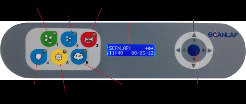
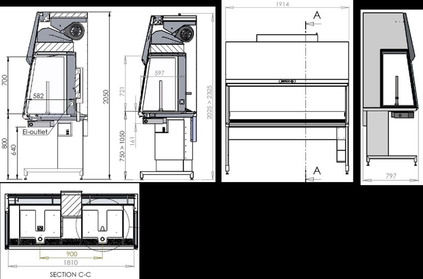
30 Version 2.1: February 10, 2014TECHNICAL SPECIFICATIONS This manual covers the following MARS Models: MARS 900 IVF or LAF IVF model is illustrated MARS 900 IVF Dimensions (W x D x H) 1003 X 797 x 2050 mm Table plate standard height 80 – 85 cm Air velocity, vertical flow 0,15 m/s (adjustable 0.01 -0.70 m/s) Air Velocity, deviation +/- 10% Noise Level, ISO 6081
MARS 1200 IVF or LAF
IVF model is illustrated.

MARS 1200 IVF or LAF
Dimensions (W x D x H)                                 1303 X 797 x 2050 mm
Workspace (W x D x H)                                  1200 x 582 x 700 mm
                                                       80 – 85 cm (option 75-80 cm or 90 -95 cm or
Table plate standard height
                                                       electrically adjusted)
Air velocity, vertical flow                            0,15 m/s (adjustable 0.01 -0.70 m/s)
Air Velocity, deviation                                +/- 10%
Noise Level, ISO 6081
MARS 1500 IVF or LAF
IVF model is illustrated
MARS 1500 IVF or LAF
Dimensions (W x D x H) 1626 X 679 x 2050 mm
Workspace (W x D x H) 1560 x 558 x 647 mm
80 – 85 cm (option 75-80 cm or 90 -95 cm or
Table plate standard height
electrically adjusted)
Air velocity, vertical flow 0,15 m/s (adjustable 0.01 -0.70 m/s)
Air Velocity, deviation +/- 10%
Noise Level, ISO 6081MARS 1800 IVF or LAF
IVF model is illustrated.
MARS 1800 IVF or LAF
Dimensions (W x D x H) 1914 X 797 x 2050 mm
80 – 85 cm (option 75-80 cm or 90 -95 cm or
Table plate standard height
electrically adjusted)
Air velocity, vertical flow 0,15 m/s (adjustable 0.01 -0.70 m/s)
Air Velocity, deviation +/- 10%
Noise Level, ISO 6081MARS 1800 Dual
MARS 1800 Dual
Dimensions (W x D x H) 1930 X 679 x 2022 mm
Workspace (W x D x H) 1865 x 558 x 647 mm
80 – 85 cm (option 75-80 cm or 90 -95 cm or
Table plate standard height
electrically adjusted)
Air velocity, vertical flow 0,15 m/s (adjustable 0.01 -0.70 m/s)
Air Velocity, deviation +/- 10%
Noise Level, ISO 6081MARS 1800MP / ICSI MP model is illustrated. MARS 1800MP / ICSI Dimensions (W x D x H) 1914 X 679 x 2150mm Table plate standard height 80 – 85 cm Air velocity, vertical flow 0,15 m/s (adjustable 0.01 -0.70 m/s) Air Velocity, deviation +/- 10% Noise Level, ISO 6081
SPARE PARTS

          Article No             DESCRIPTION
         9.000.040.001           UV-light tube for MARS 900-1800
         9.000.040.011           Light tube for MARS 900
         9.000.040.012           Light tube for MARS 1200
         9.000.040.013           Light tube for MARS 1500
         9.000.040.014           Light tube for MARS 1800
         9.000.050.001           Main HEPA filter for MARS 900
         9.000.050.002           Main HEPA filter for MARS 1200
         9.000.050.003           Main HEPA filter MARS 1500
         9.000.050.004           Main HEPA filter MARS 1800
         9.000.050.005           Main circuit board
         9.000.050.006           Flow sensor
         9.000.050.007           Light ballast for MARS 900 1200
         9.000.050.008           Light ballast for MARS 1500 1800
         9.000.050.012           Display board
         9.000.050.010           UV-light ballast

                         Version 2.1: February 10, 2014             37
OPERATING THE MICROSCOPE LIGHT SOURCE
Depending on the customer order and on the configuration selected, below is the operating manual of the light
sources provided by ORIGIO.
See also the section entitled “Working Heated Surface and ORIGIO Light Source”.
ORIGIO Halogen Light Source Model TLB 4000
Figure 1
Figure 2 Figure 3
Operating the light source
On/off switch:
The power switch is located on the rear of the base. Turn the power switch on.
38 Version 2.1: February 10, 2014Variable voltage adjustment:
Light intensity is adjusted by the knob on the left side of the base. (Figure. 3)
Condensing lens focusing knob:
This knob is located on the right side of the base in the back. By sliding the knob back and forth you can focus the
light onto the mirror. The knob can be locked in position by rotating it right (to the back).
Mirror linear movement adjusting ring:
This is the inner knob on the mirror controls assembly. The function of this knob is to adjust the amount of friction in
the linear front to back movement of the mirror and tilting of the mirror. Clockwise tightening of the knob increases
the friction in the assembly. This will also lock down the rotational movement.
To lock down the mirror, turn the knob gently.
DO NOT OVER TIGHTEN
Mirror front to back rotation knob:
This is the outer knob on the mirror controls assembly. The function of this knob is for tilting the mirror front to back.
Its travels are limited to prevent the mirror from hitting the top or bottom of the base. The travel range is 0° - 55°.
Brightfield operation:
To achieve a brightfield illumination, the mirror should be moved to its rear most
position, (away from user), and the light directed through the glass stage plate.
Single direction darkfield:
To achieve one directional darkfield the mirror can be moved to its forward most
position (towards the user), the light will be directed back through the glass
stage plate.
Replacing the light bulb
DO NOT TOUCH A HALOGEN LIGHT BULB WITH BARE HANDS, AS IT WIL
LEAVE RESIDUE ON THE BULB.
Switch off the light source on the main switch on the back.Pull out the lamp housing at the back, as indicated in
Figure 3.
Remove the defective bulb as indicated in Figure 2 and replace it with a new one. Replace the housing back by
pushing it into its location located at the back of the lamp source.
Switch on the Light source with the ON/ OFF switch.
Version 2.1: February 10, 2014 39ORIGIO LED Light Source Model TLB 7000 Please refer to the User Manual provided with the light source. 40 Version 2.1: February 10, 2014
OPERATING THE STEROMICROSCOPE HEATED GLASS STAGE – HG37 MODEL
                     Depending on the customer order and on the configuration selected, the work
                     surface can be fitted with a heated glass stage. To Operate ORIGIO’s HG37
                     Heated Glass, please refer to the user manual provided with the device.

                         Version 2.1: February 10, 2014                                      41
OPERATING THE LCD MONITOR
Depending on the customer order and on the configuration selected,
please refer to the User manual provided with the monitor.
42 Version 2.1: February 10, 2014WARRANTY AND LIABILITY
Limited Warranty
ORIGIO Equipment warrants to the purchasers of all devices and products solely manufactured by ORIGIO
EQUIPMENT.
In the event of product failure under normal use, due to defects in material or workmanship, within a period of
twenty four months (24) months from the date of invoice of the Product and from the point of origin, the product will
be repaired, or at ORIGIO EQUIPMENT option, replaced, at no charge. ORIGIO EQUIPMENT assumes that the
Purchaser is experienced in the use of this device and is able to judge from his/her own expertise the suitability or
otherwise of the product for the intended use. This limited warranty does not apply to products subjected to
abnormal use or conditions, improper storage, damaged by accident, misuse or abuse, improper line voltage,
products whose serial number has been altered, to products not shipped in accordance with the recommendations
of ORIGIO EQUIPMENT , and/or to products altered or serviced by anyone other than ORIGIO EQUIPMENT
authorized distributors. Distributor is responsible for the labor and travel costs during this period.
This limited warranty is exclusive and in lieu of all other warranties whether written, oral, expressed or implied. In
particular, ORIGIO EQUIPMENT does not warrant that the product is suitable for the needs of the purchaser and
there are no warranties given as to merchantability or fitness for a particular purpose other than the one specified in
ORIGIO EQUIPMENT literature that accompanies every specific product.
ORIGIO EQUIPMENT reserves the right to change or discontinue this product without prior notice.
Liability:
Because ORIGIO EQUIPMENT has no control or influence over the conditions under which this device is used,
over its method of use or administration, or on handling of the product after it leaves its possession ORIGIO
EQUIPMENT takes no responsibility for the results, use and/or performance of the product. ORIGIO EQUIPMENT
expects that use of the product will be confined to trained and expert users.
In no event shall ORIGIO EQUIPMENT be liable for any direct or indirect damages including incidental,
consequential or special damages, arising out of or in connection with the use or performance of the product.
If ORIGIO EQUIPMENT provides you with technical documentation, this does not authorize you to perform repairs,
adjustments or alterations on the device or accessories.
No representative of ORIGIO EQUIPMENT and no vendor of the product is authorized to change any of the
foregoing terms and conditions, and the purchaser accepts the product subject to all terms and conditions herein,
subject always to any contrary provisions which are necessarily implied by stature or law notwithstanding the within
terms and conditions.
Replacement
As mentioned in the Limited Warranty, The decision whether to provide any remedy or whether to refund any
portion of the purchase price shall be at the discretion of ORIGIO EQUIPMENT.
Before returning a product for any reason, please contact your nearest ORIGIO EQUIPMENT distributor for
assistance and instructions.
Version 2.1: February 10, 2014 43ORIGIO a/s
Knardrupvej 2
2760 Måløv
Denmark
Tel: +45 46 79 02 00
Fax: +45 46 79 03 00
Customer.service@origio.com
www.origio.com
44 Version 2.1: February 10, 2014You can also read