SMARTOUCH DIGITAL USER MANUAL - ACC Spas - Applied ...
←
→
Page content transcription
If your browser does not render page correctly, please read the page content below
SMARTOUCH DIGITAL

                                    2.5” X 5.5"

                                                                                                USER
                                                                                               MANUAL
                                   3.25” X 7.25"

                                                                                                                    APPLIED
                                                                                                                    COMPUTER
                              SmarTouch Digital                                                                     CONTROLS
                                                                                          701 W. Foothill Blvd., Azusa, CA 91702
                      © 1999 Applied Computer Controls.                                    (626) 969-9655 Fax (626) 334-4809
  SmarTouch & SmarTouch Digital are trademarks of Applied Computer Controls.                       www.acc-spas.com
This manual may not be copied or reproduced without permission, in part or in total.
                                                                    Rev. 05/2017-ACC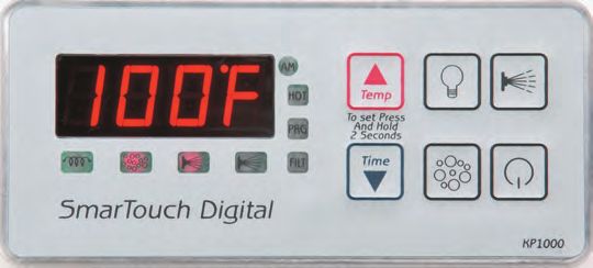
Micro-processor technology is becoming a familiar name in the spa in-        NO    Check for the following:
                                                                                   1- Voltage at the Heater Contactor Coil Relay. Across the White and Yellow wires. 120V or 240V depending on
dustry. Here, at Applied Computer Controls, we produced our first intelli-            power rating on contactor relay.
gent microprocessor based spa control system, in 1981-82. The SC-100                  If power is present and contactor does not engage, replace contactor.
and SC-200; the forerunners of intelligent electronic spa controls.                   If there is no power replace PCBoard
                                                                                   2- Check power at load / output (right) side of contactor . If there is power go to next step. If not go back to step one.
                                                                                   3- Check power at Heater ELEMENT. If no power then High Limit relay on PCBoard is NOT -- closing. Remove plastic
Today, SmarTouch Digital includes more than 30 years experience.                      dust cover off and inspect relay contacts. Replace PCBoard.
SmarTouch Digital, is a fourth generation microprocessor-based control
system. A reliable energy efficient spa controller, so advanced but easy     OVERHEAT ERROR CODES ( OH or HLEr) but spa water temperature is not.
to operate, is conveniently located at your fingertips. A high intensity,    Allow enough time for the sensors to cool down. Then clear the error code by pressing the SET button.
oversized characters, LED display or our multi colored LCD display, keeps
you informed of the spa temperature, time-of-day and elapsed time and        1-Turn temperature down to lowest setting & press the SET key

a list of error codes, to inform and identify a malfunction.                 2- Press SET a second time and allow the low speed Jets to run for 2-3 minutes

Safety and reliability are built-in to meet or exceed the most stringent,    3-Is temperature reading dropping? Does it match the thermometer reading in the spa ?
                                                                             4-If YES . there is flow restriction. Clean / inspect or remove filter cartridge. Or secondary bypass intake to the pump is
up to date requirements set by (UL) Underwriters Laboratories.               blocked or not installed.

SmarTouch Digital is the culmination of proven designs and extensive         5-Raise the temperature setting to 4 degrees above water temperature. Average heat gain is about 30 minutes. If there is
                                                                             rapid heat gain go back to step #4.
testing… from Applied Computer Controls.
                                                                                                                                                                                                 QRC- 215A

                                                                                                                      SAVE THIS MANUAL

                                                                                                  Make it available for other spa users.
                                                                                         You should also have a spa user’s manual which ex-
                                                                                         plains how to care for your spa. Please read and follow
                                                                                         all instructions in your spa user’s manual. Maintaining
                                                                                         the proper levels of pH and the sanitizer will extend the
                                                                                         life of your spa equipment. Improper chemical levels
                                                                                         in the spa are sure to cause premature heater failure
                                                                                         as well as failure of other components in the system.
                                                                                         Failures caused by chemical imbalance are not cov-
                                                                                         ered by warranty.

                                                                                                                                      Page 26
TECH TALK......TROUBLESHOOTING GUIDE
                                                     For SmarTouch Digital                                                                    TABLE OF CONTENTS
ERROR CODES

COLD Water temperature below 40 F.                               OH Water temperature above 108 F.                           INTRODUCTION . . . . . . . . . . . . . . . . . . . . . . . . . . . . . . . . 3
SESH Temperature sensor shorted.                                 SEOP Temperature sensor open or disconnected
HLer Overheat condition or overheat sensor disconnected          PSOL Pressure-switch open with low speed jets ON.
PSOH Pressure-switch open with high speed jets ON                PSOC Pressure-switch open with circulating pump ON          TEMPERATURE SETTING . . . . . . . . . . . . . . . . . . . . . . . . 4
Error code PSOL? PSOH? PSOC?                                                                                                 SETTING TIME-OF-DAY. . . . . . . . . . . . . . . . . . . . . . . . . . 5
EXPLANATION:
No water pressure. Pressure Switch Open.                                                                                     COOL-DOWN TIMER . . . . . . . . . . . . . . . . . . . . . . . . . . . . 5
-Check if circulation /filtration pump is running.
-Check for the following symptoms:
                                                                                                                             USER TIMER . . . . . . . . . . . . . . . . . . . . . . . . . . . . . . . . . . . 5
PUMP running but no water flow
-Check for possible airlock. Pump is not primed. Check for a closed gate valve.
                                                                                                                             SPA-SIDE CONTROL PANEL 2020 . . . . . . . . . . . . . . . . . 6
PUMP does not run.
-Is primary pump connected.                                                                                                  SPA-SIDE CONTROL PANEL 1000 . . . . . . . . . . . . . . . . . 7
Only a trained or qualified technician can perform the following procedure
                                                                                                                             USER & SYSTEM OPTIONS
-Measure, using a voltmeter, INCOMING POWER.                                                                                 SELF-DIAGNOSTIC ERROR CODES . . . . . . . . . . . . . . . . 8-9
-240 VOLTS. Across L1 & L2 at Terminal Block ( 240V installations only)
-Check pump power rating.
Measured voltage at pump connector MUST match power rating at pump motor label.                                              START-UP PROCEDURE. . . . . . . . . . . . . . . . . . . . . . . . . . 10
-Measure 240 or 120 Volts @ primary pump connector (pump 1) across WHITE and RED for low speed (PSOL) and WHITE
& BLACK for high speed jets.(PSOH)
                                                                                                                             WATER PRESSURE. . . . . . . . . . . . . . . . . . . . . . . . . . . . . . 10
NO POWER READING AT PUMP CONNECTOR:
Replace PCBoard. Possible burnt fuse or pump relay circuit defective, provided incoming power is verified at main Terminal   FILTER CARTRIDGES . . . . . . . . . . . . . . . . . . . . . . . . . . . . 10
Block.

POWER O.K.: Replace pump.                                                                                                    IMPORTANT SAFETY INSTRUCTIONS . . . . . . . . . . . . . 11
PUMP runs and there is flow:
- Heater manifold must be plumbed to pump discharge or output side to activate pressure switch.                              PROGRAMMING (OPTIONAL) . . . . . . . . . . . . . . . . . . . . 12-16
-Check Pressure Switch connections at Pressure Switch.
-Jumper across pressure switch terminals. If error code goes away check Pressure Switch calibration or P/S is defective.
                                                                                                                             ELECTRICAL INSTRUCTIONS . . . . . . . . . . . . . . . . . . . . 17-19
Spa will not heat.
                                                                                                                             FCC REGULATORY APPROVAL . . . . . . . . . . . . . . . . . . . . 20
Check for error codes ‘OH’ or “HLEr”. If YES then check for the following:
-Good water flow.
-Possible air pocket inside Heater Manifold or an Air Lock                                                                   WIFI FEATURE (OPTIONAL) . . . . . . . . . . . . . . . . . . . . . . 21
1- Is Heater indicator light ON at spaside control panel?
Yes Go to next step.
                                                                                                                             WIRING DIAGRAM. . . . . . . . . . . . . . . . . . . . . . . . . . . . . . 22-23

2- Is Red indicator light located at equipment enclosure “ON”?                                                               EXPLODED VIEW . . . . . . . . . . . . . . . . . . . . . . . . . . . . . . . 24
YES -Burnt element. Replace heater element.

                                                                                                                             TROUBLESHOOTING . . . . . . . . . . . . . . . . . . . . . . . . . . . . 25-26
                                                         Page 25
INTRODUCTION
Thank you for buying a spa equipped with a SmarTouch Digital con-
trol system. Many years of experience went into the design of this
family of controls. You can be assured your spa control system is the
most advanced, it is highly reliable and will serve you for many years
to come.

The control system has been designed with you, the user in mind. It
is very easy to operate and requires a minimal effort on your part.
You may use it just as it comes to you and without any programming.
Yet you have the option of getting deeply involved in the inner work-
ings of the control if you so choose. You can custom tailor it to fit
your needs.

Please take the time to read at least the first section (next page) “IN
A HURRY – READ THIS” portion of the manual before starting to use
your spa for the first time. You can familiarize yourself with the rest
of the manual at your leisure.

             The more efficient the system is the
                    less energy it uses.
The concept behind SmarTouch Digital is to maintain the desired
temperature setting and water filtration with the least amount of en-
ergy consumption.

Temperature and Overheat sensors are located at the Stainless Steel
heater manifold, the coldest and hottest spot where true tempera-
ture is measured and to detect Freeze and Overheat conditions.

Considering the large volume of cooler water in the plumbing, pump
and heater manifold, low speed primary pump is activated for five
minutes every three hours to stabilize spa temperature, prior to ac-
tivating the heater. Estimated 102F water temperature drop at 55F
ambient air temperature is about half a degree Fahrenheit in a well
insulated spa. Heater will not start at this point until next cycle. Tem-
perature must drop by 1F before heater is activated.

                                Page 3                                      Page 24
IN A HURRY - READ THIS
                                   SmarTouch Digital comes to you with a universal set of default
                                   settings. If you choose to keep these settings, then you only
                                   need to remember 2 things: how to set the spa temperature and
                                   to press the SET key whenever you are done using the spa.

                                   Setting Temperature                       Both buttons are used to select, increase
                                                                             or decrease temperature or time setting.
                                   The UP(TEMP) & DOWN(TIME) arrows.
                                                                             Note: Both keys are active when pressed
                                                                             individually and held down 2 seconds, to
                                                                             eliminate accidental changes.

                                   Press and hold for 2 sec. the UP (TEMP) arrow key.

                                   Controller will display current spa temperature.
                                   Use the UP or DOWN arrow keys to select
WIRING DIAGRAM FOR SC-1100 (JR.)   desired temperature.

                                   *To enter new temperature press → SET key.

                                   The controller will:
                                   - Lock-in the new temperature.
                                   - Display current spa temperature.

                                     IMPORTANT: Always turn down the heat before you drain the spa.

                                   *Note:
                                   Once you select the TEMP or TIME and the SET key is not pressed within
                                   30 seconds the controller reverts to the previous setting and the change
                                   will not take effect.

                                   The SET Key
                                   After using the spa, press the SET key to tell the micro controller you are
                                   done using the spa. It will then take over the spa’s management, including
                                   the different filtration cycles, heat maintenance, economy modes and
                                   protection against freezing.
  WIRING DIAGRAM FOR SC-3000
            Page 23                                                 Page 4
S ETTING TIM E-OF-DAY
Setting Time-Of-Day
Press and hold for 2 sec. the DOWN (Time) arrow key.
Controller will display 12:00 noon. Use OR to set the
correct time-of-day.
*After every selection “Hours , Minutes” press → SET key.
Cool-Down Timer
A 30-second timer keeps the low speed jets, ON, after the heater turns
OFF, to remove all residual heat from the heater element.
User Timer
A built-in, 20 minutes elapsed-time clock switches off any active function.
Economy mode. Water & Energy Management. WIRING DIAGRAM FOR SMTD 1000
The Economy mode manages water temperature, filtration and energy
consumption knowing “when” to heat to maintain water temperature.
The Economy mode starts when the heater is turned off and the spa is
not in use.
Upon entering the ECONOMY mode the message “ECON” is displayed.
During the Economy mode the spa controller is in stand-by, three hours
at a time, monitoring and sampling the water temperature.
At the end of every Economy period which is 3 hours the controller ac-
tivates the low jets only for 5 minutes to perform the following: COM2 J14
1-Filter and sanitize the water. Check your spa manual for the type of
sanitizer in your spa.
2- Stabilize the water temperature and heat if necessary, in that case the
low jets run more than 5 minutes for the duration of the heating cycle.
Important: Tie down your spa cover to minimize heat loss and to con-
serve energy.
Note: The message “ECON” is not an error code.
WIRING DIAGRAM FOR SMTD 2000
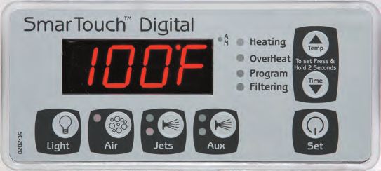
Page 5 Page 22W IFI C ONNEC TIV ITY PR OCEDURE SPA-SIDE CONTROL PANEL 2020
Switch OFF power to the spa. FUNCTIONS
Disconnect spaside control panel / keypad. If primary pump is dual Speed. Press once to
Open WIFI box and reconnect keypad to the WIFI board. activate the low jets. Press again for high jets.
A third depression turns the jets OFF, if the
Connect WIFI board to the spa controller then turn power back ON. heater is off.
Select “Settings” on your smart phone. Choose Wireless Networks / WIFI. Press, for third or fourth pump. If auxillary pump
is dual speed the AUX button functions
Scan Available networks. as above.
Select AGI_BOARD XXX.
Press, for air bubbles or second pump
Your phone should connect to the Board. single speed.
GO to your phone Browser and enter //192.168.1.3.
Touch “Display Scan Results”. Light switch ON/OFF
Select your home network (Router).
Enter the router PASSWORD or (WEP Key) if password is not recognized.
*Optional
Enter your e-mail.
• TEMPERATURE
Re-enter your e-mail. • TIME OF DAY
Touch “ACCEPT”.
Touch “Join”.
Page should exit or Time out.
Check your e-mail on your phone. Depending on the phone service this may take
1-2 minutes. You can also check for the same email on your home computer.
Enter a USER name (6 characters, NO spaces).
Click “Register”.
Bookmark this page and add it to your phone home page.
**You can forward the link or the registration email up to nine more spa users.
TO INVERT THE TEMPERATURE DISPLAY:
Use different spa name every time. PRESS THE SET & UP ARROW KEYS TOGETHER AT THE SAME TIME.
Page 21 Page 6SPA-SIDE CONTROL PANEL 1000 FCC REGULATORY APPROVAL
U.S.A.
Contains FCC ID: W7OMRF24WG0MAMB
This device complies with Part 15 of the FCC Rules. Operation is subject to the
following two conditions: (1) this device may not cause harmful interference,
and (2) this device must accept any interference received, including interfer-
ence that may cause undesired operation.
This equipment has been tested and found to comply with the limits for a Class
B digital device, pursuant to part 15 of the FCC Rules. These limits are designed
to provide reasonable protection against harmful interference in a residential
installation. This equipment generates, uses and can radiate radio frequency
energy, and if not installed and used in accordance with the instructions may
cause harmful interference to radio communications. However, there is no guar-
antee that interference will not occur in a particular installation. If this equip-
ment does cause harmful interference to radio or television reception, which
can be determined by turning the equipment off and on the user is encouraged
to try to correct the interference by one or more of the following measures:
• Reorient or relocate the receiving antenna.
FUNCTIONS • Increase the separation between the equipment and receiver.
• Connect the equipment into an outlet on a circuit different from that to which
the receiver is connected.
Press once to activate the low jets. Press again • Consult the dealer or an experienced radio/TV technician for help.
for high jets. A third depression turns the jets To satisfy FCC RF Exposure requirements for mobile and base station transmis-
OFF, if the heater is off. sion devices, a separation distance of 20 cm or more should be maintained be-
tween the antenna of this device and persons during operation. To ensure
compliance, operation at closer than this distance is not recommended.
Press, for air bubbles or second single The antenna(s) used for this transmitter must not be co-located or operating in
speed pump if applicable. Button will be conjunction with any other antenna or transmitter.
marked “AUX”. CANADA
Contains transmitter module IC: 7693A-24WG0MAMB
This device complies with Industry Canada license-exempt RSS standard(s).
Light switch ON/OFF. Operation is subject to the following two conditions: (1) this device may not
cause interference, and (2) this device must accept any interference, including
interference that may cause undesired operation of the device.
Le présent appareil est conforme aux CNR d’Industrie Canada applicables aux
TO INVERT THE TEMPERATURE DISPLAY: appareils radio exempts de licence. L’exploitation est autorisée aux deux con-
PRESS THE SET & UP ARROW KEYS TOGETHER AT THE SAME TIME. ditions sui vantes: (1) l’appareil ne doit pas produire de brouillage, et
(2) l’utilisateur de l’appareil doit accepter tout brouillage radioelctrique subi,
même si le brouillage est susceptible d’en compromettre le fonctionnement.
Page 7 Page 20BRANCH CIRCUIT BREAKER REQUIREMENTS USER OPTIONS
240 Volts 4 Wire System 30/50 Amp 2 Pole Breaker
USE COPPER CONDUCTOR ONLY. #6 AWG WIRE
120 Volts 3 Wire System 20 Amp 1 Pole Breaker
CAUTION: A new breaker must be used for a new spa installation. Do not use
an existing or used breaker.
GFCI: All spa installations must be protected by a GFCI. If your spa control box
does not include an integrated GFCI then you must use a GFCI breaker per Na-
tional Electrical Code requirements.
120/240 Volt Conversion. All spas are shipped configured for 240 volt (4
wire systems). Please check the nameplate on the control enclosure to identify
the type of system in your spa. If the nameplate indicates a 120/240 Volt type
system, then it is possible to convert the spa to 120 volt operation.
30/50 Amp Conversion. Some homes may have limited power service. It is pos-
sible to operate a 240 volt spa system using a 30 amp breaker. Connect 240 volt
power to the system as previously described, then set it to operate in the low
power mode.
To Save Changes And Exit Go To Code SEnd
To Exit Without Saving Changes Go To Code CAnC
120 or LOW POWER CONVERSION
-Press the UP and DOWN arrows simultaneously.
-Press UP arrow and go to Code U7 press SET. U7 will change to ‘1’
-Press UP arrow and go to Code U8 press SET. U8 will change to ‘1’
-Press UP arrow and go to Code P3 press SET. P3 will change to ‘1’
-Press UP arrow and go to Go to code SEND and press SET (Ignore and do not
change the rest of the codes as the can alter the spa settings).
If P3 is “0” = High power
SELF DIAGNOSTIC CODES
If P3 is “1” = Low power
Error Messages
120V CONVERSION ONLY
Install jumper wire across “Neutral Terminal” and “Line 2 Terminal” at the main
Terminal Block.
Note: Only experienced service personnel should perform conversions.
Improper modifications may cause damage to the control system
and/or the attached heater and pump motors.
Page 19 Page 8S Y S TEM OPTIONS ELECTRICAL INSTALLATION INSTRUCTIONS
To Save Changes And Exit Go To Code SEnd
To Exit Without Saving Changes Go To Code CAnC
S ELF D IA GNOS TIC CODES
Error Messages
Page 9 Page 18ELECTRICAL CONNECTION INSTRUCTIONS. START-UP PROCEDURE
Once the spa is delivered and the electrical installation accomplished, the next
NOTICE: All spa electrical wiring must be performed by a qual- step is to fill it and heat the water.
ified licensed electrician and must meet all NEC (National Elec- IMPORTANT
trical Code) and state and local codes and requirements. It is recommended to perform the following procedure when you
drain and refill the spa, to protect the heater element.
DANGER – RISK OF ELECTRIC SHOCK
• Power must be turned OFF at the circuit breaker and at the G.F.C.I before you start.
1. The lines carrying power to the spa must be dedicated to the • Open the access door and inspect all fittings to be tight and slide-valves fully extended.
spa and should not be shared with any other appliance(s). • Fill the spa, using your garden-hose, to the proper water level (half way mark on
the skimmer door).
2. All electrical wiring lines must originate from the electrical • To apply power, push the RESET (ON) button at the G.F.C.I. & reset Circuit Breaker
panel and terminate, hard wired, into the electrical wiring to the ON position.
compartment. The use of extension cords or plug type termi- • Push the Jets button at the Spa Side Control Panel activating the high speed
nation is expressly prohibited and voids the warranty. pump. Keep pump running for at least three minutes to purge the air out of the
plumbing.
3. Do not use aluminum wiring. Use only copper wiring. • Once air bubbles stop coming out of the jets and the pump is primed select the
desired temperature.
4. Wire gauge must be in accordance with NEC requirements for IMPORTANT: TURN DOWN THE HEAT BEFORE YOU DRAIN AND REFILL
the distance from current source to spa and the current rating YOUR SPA TO PROTECT THE HEATER.
as stated on the ID label that is attached to the control enclo-
sure. WATER PRESSURE
5. All wiring must be shielded by a grounded metal conduit. The FOR YOU TO KNOW…….!
conduit must terminate at the electrical access compartment PSOL or PSOH error codes = NO WATER PRESSURE
either from the bottom of the spa or through a hole in the side A pressure-switch protects the heater element when the water level drops below
paneling of the spa. the recommended level. The switch is activated by water pressure in the heater
housing, meaning the pump is running and there is water in the spa.
6. For a 120 volt system the line wire (black) is connected to the In a new installation, or when the spa is drained then refilled, a small volume of
terminal block lug labeled LINE1. The neutral wire (white) is air is trapped in the plumbing and in the heater-housing, lowering the pressure,
connected to the center lug labeled NEUT, and the ground wire disabling the pressure-switch, consequently shutting down the heater.
(green) is connected to the ground lug labeled G or GROUND.
Or, the opposite is also possible, where the trapped air exposes part of the
7. For a 240 volt 4 wire system, connect Line1, Neutral and heater element but not enough to disable the pressure-switch resulting in a
Ground wires as in #6 above. The fourth wire is the Line2 wire burnt element. To avoid damage to the heater, refer to the start-up procedure.
(red) and it is connected to the lug labeled LINE2.
FILTER CARTRIDGES
8. For a 240 volt 3 wire system, if applicable, connect black line
wire to LINE1 terminal, connect red line wire to LINE2 terminal The filter cartridge(s) must be cleaned periodically. It should be totally sub-
and the green wire to the ground lug. There is no neutral. merged. If the top of the cartridge is above water level, air is sucked into the
pump's intake causing pump surges, lower pressure and damage to the heater.
Page 17 Page 10Msg Min Def Max Detail
IMPORTANT SAFETY INSTRUCTIONS
CALB 198 208 218 This is not a time element. It is one of
the distinctive features of the Smartouch
Control System. The number is internal
and in indicative of what the processor
sees as temperature. It is used to calibrate
the temperature reading. Increase this
value by 1 to decrease the displayed
temperature by 1⁄2 a degree. Decrease this
number by 1 to increase displayed
temperature by 1⁄2 a degree. For example
the controller is displaying a temperature 2
degrees lower than real temperature
increase the number by 4 to get a correct
reading. The total range of this parameter
is 10 degrees Fahrenheit. Before doing a
calibration Please read warning note at
end of this page.
SEND This menu message has no numerical
value. Pressing SET while it is displayed
records and saves all changes made to all
parameters.
CANC This menu message also has no value.
Pressing SET while it is displayed
discards all changes made to all
parameters and restores last saved or
previous values.
WARNING
The recommended maximum temperature of a spa is
100˚F. The absolute maximum beyond which no person
should ever be exposed to is 104˚F.
Page 11 Page 16Msg Min Def Max Detail
PROGRAMMING
CLDN 30 60 180 Cool Down cycle in seconds. Whenever SmartTouch Digital comes with factory settings. Programming the
the heater is turned off the pump keeps SmartTouch controller is optional. The following options are nec-
running the extra seconds to even the essary only if you have certain requirements or you need to in-
temperature of the heater element and crease the filtration and heating cycles.
the surrounding water to prevent scale
build up and premature heater failure. Parameter Programming is a means by which the spa owner
/ user can change the various timing elements and calibrate tem-
ECL 60 180 240 Economy Cycle Length. Time in minutes perature. The process is simple and intuitive. Only 3 keys are
to specify the intervals between spa
temperature sampling when the spa is used: UP, DOWN, and SET. To program one or more parameters
not in use. During this period the spa is follow the outlined this procedure:
in economy mode. Temperature is
sampled at the end of the period. Press 1. Press SET and DOWN keys together. The first message
any key to cancel this mode. in the menu, FP1 will be displayed.
NOTE: In severe cold weather
conditions set ECL to 60 minutes. 2. Use the UP & DOWN keys to scroll thru the messages
in the menu.
CHCL 0 60 180 Channel Clear. Time in seconds to clear
the air channel and the secondary 3. Press the SET key to display the current value
pump(s) plumbing if the spa has not associated with the current message.
been used for a period of 24 hours. This 4. Use UP or DOWN keys to increase or decrease the value.
prevents water stagnation in the
plumbing. 5. Press SET to lock in the new value and return to menu.
UTO 10 20 60 User Time Out. The time in minutes from 6. If another item needs programming go to number 2 above.
starting any device, after which all
devices will be turned off, and the spa 7. To Save changes scroll to message SEND and press SET.
put in “not in use mode”. If you should
leave the spa with a pump or light 8. To discard changes and restore previous values scroll
running, it will be turned off after the to message CANC and press SET.
specified time.
The menu of the parameters is circular. Scrolling is from first to
PUF 30 60 180 Post Use Filtration. Time in minutes to last or from last to first.
perform Post Use Filtration this is the
optimal time to filter the spa. When you
have finished using the spa, that is when When in programming mode please note that this mode will be
it needs filtration the most. Press the cancelled if there is no key activity for a period of 60 consecutive
SET key to turn off all functions and start seconds. Programming mode is aborted and all changes will be
filtering.. This cycle is performed only restored to previous values.
once and after pressing the SET key. It is
in addition to the standard filtration On the following page is an example of how to program a filtra-
cycles. Pressing any other device key tion period. When in programming mode you may program as
will cancel this function.
many parameters as needed.
Page 15 Page 12SETTING FILTRATION PERIODS & SILENT MODE PARAMETER MENU LIST
* FP1, FP2, FP3, FP4 & SIL Press momentarily the “SET” & “DOWN ARROW” keys at the
same time to access the following options.
BEFORE YOU START THIS PROCEDURE PLEASE MAKE SURE YOU
SET THE CORRECT TIME-OF-DAY. Msg Min Def Max Detail
Note the a.m. LED light FP1 12:00 Start time of filtration period 1
FP2 12:00 Start time of filtration period 2
-Press SET & DOWN arrow keys together at the same time. FP3 12:00 Start time of filtration period 3
FP4 12:00 Start time of filtration period 4
-Code “FP1” is displayed.
Note : If filtration periods overlap,
-Press the SET key. the most recent period (last) is in
effect.
- Enter the desired start time to begin the First Filtration Period
FP1. Enter the hour then press “SET”. Enter the minutes then SIL 12:00 Start time of the silence period.
press “SET” This is a period which nothing will
run. It overrides all filtrations, the
-Press UP arrow and go to code “FP1d”. economy cycle, and temperature
sampling. Except if temperature
-Press “SET”. Enter the number of hours or the duration of the drops below 40 degrees. A spa may
First Filtration Period in minutes. Maximum is 4 hours, then be installed near a bedroom and
press “SET”. need not come on at specific times.
-Repeat above procedure for FP2, FP3, and FP4 if necessary. FP1d 0 0 240 Duration in minutes FP1 timer will run.
FP2d 0 0 240 Duration in minutes FP2 timer will run.
-After you have programmed the Filtration Periods press UP arrow FP3d 0 0 240 Duration in minutes FP3 timer will run.
(ignore the rest of the codes) and go to code “SEND”. FP4d 0 0 240 Duration in minutes FP4 timer will run.
-Press SET to exit and save the new values. SILd 0 0 12 Duration in hours the Silence Timer
runs. Only a user may override the
‘UP ARROW’ KEY IS MARKED ‘TEMP’ silence timer.
‘DOWN ARROW’ KEY IS MARKED ‘TIME’
Note : Keep the value of any time to 0 to keep
NOTE: it from running. Filtration timers must be programmed
IF POWER TO THE SPA IS TURNED OFF OR INTERRUPTED PRO- first one first. If the FP1d (first) timer has a duration of
GRAMMING FOR THE “FILTRATION PERIODS” IS NOT AFFECTED 0, Auto Filtration will be in effect and all 4 programmed
TIME OF DAY MUST BE RE-ENTERED. timers will be disabled.
* Optional
Page 13 Page 14SETTING FILTRATION PERIODS & SILENT MODE PARAMETER MENU LIST
* FP1, FP2, FP3, FP4 & SIL Press momentarily the “SET” & “DOWN ARROW” keys at the
same time to access the following options.
BEFORE YOU START THIS PROCEDURE PLEASE MAKE SURE YOU
SET THE CORRECT TIME-OF-DAY. Msg Min Def Max Detail
Note the a.m. LED light FP1 12:00 Start time of filtration period 1
FP2 12:00 Start time of filtration period 2
-Press SET & DOWN arrow keys together at the same time. FP3 12:00 Start time of filtration period 3
FP4 12:00 Start time of filtration period 4
-Code “FP1” is displayed.
Note : If filtration periods overlap,
-Press the SET key. the most recent period (last) is in
effect.
- Enter the desired start time to begin the First Filtration Period
FP1. Enter the hour then press “SET”. Enter the minutes then SIL 12:00 Start time of the silence period.
press “SET” This is a period which nothing will
run. It overrides all filtrations, the
-Press UP arrow and go to code “FP1d”. economy cycle, and temperature
sampling. Except if temperature
-Press “SET”. Enter the number of hours or the duration of the drops below 40 degrees. A spa may
First Filtration Period in minutes. Maximum is 4 hours, then be installed near a bedroom and
press “SET”. need not come on at specific times.
-Repeat above procedure for FP2, FP3, and FP4 if necessary. FP1d 0 0 240 Duration in minutes FP1 timer will run.
FP2d 0 0 240 Duration in minutes FP2 timer will run.
-After you have programmed the Filtration Periods press UP arrow FP3d 0 0 240 Duration in minutes FP3 timer will run.
(ignore the rest of the codes) and go to code “SEND”. FP4d 0 0 240 Duration in minutes FP4 timer will run.
-Press SET to exit and save the new values. SILd 0 0 12 Duration in hours the Silence Timer
runs. Only a user may override the
‘UP ARROW’ KEY IS MARKED ‘TEMP’ silence timer.
‘DOWN ARROW’ KEY IS MARKED ‘TIME’
Note : Keep the value of any time to 0 to keep
NOTE: it from running. Filtration timers must be programmed
IF POWER TO THE SPA IS TURNED OFF OR INTERRUPTED PRO- first one first. If the FP1d (first) timer has a duration of
GRAMMING FOR THE “FILTRATION PERIODS” IS NOT AFFECTED 0, Auto Filtration will be in effect and all 4 programmed
TIME OF DAY MUST BE RE-ENTERED. timers will be disabled.
* Optional
Page 13 Page 14Msg Min Def Max Detail
PROGRAMMING
CLDN 30 60 180 Cool Down cycle in seconds. Whenever SmartTouch Digital comes with factory settings. Programming the
the heater is turned off the pump keeps SmartTouch controller is optional. The following options are nec-
running the extra seconds to even the essary only if you have certain requirements or you need to in-
temperature of the heater element and crease the filtration and heating cycles.
the surrounding water to prevent scale
build up and premature heater failure. Parameter Programming is a means by which the spa owner
/ user can change the various timing elements and calibrate tem-
ECL 60 180 240 Economy Cycle Length. Time in minutes perature. The process is simple and intuitive. Only 3 keys are
to specify the intervals between spa
temperature sampling when the spa is used: UP, DOWN, and SET. To program one or more parameters
not in use. During this period the spa is follow the outlined this procedure:
in economy mode. Temperature is
sampled at the end of the period. Press 1. Press SET and DOWN keys together. The first message
any key to cancel this mode. in the menu, FP1 will be displayed.
NOTE: In severe cold weather
conditions set ECL to 60 minutes. 2. Use the UP & DOWN keys to scroll thru the messages
in the menu.
CHCL 0 60 180 Channel Clear. Time in seconds to clear
the air channel and the secondary 3. Press the SET key to display the current value
pump(s) plumbing if the spa has not associated with the current message.
been used for a period of 24 hours. This 4. Use UP or DOWN keys to increase or decrease the value.
prevents water stagnation in the
plumbing. 5. Press SET to lock in the new value and return to menu.
UTO 10 20 60 User Time Out. The time in minutes from 6. If another item needs programming go to number 2 above.
starting any device, after which all
devices will be turned off, and the spa 7. To Save changes scroll to message SEND and press SET.
put in “not in use mode”. If you should
leave the spa with a pump or light 8. To discard changes and restore previous values scroll
running, it will be turned off after the to message CANC and press SET.
specified time.
The menu of the parameters is circular. Scrolling is from first to
PUF 30 60 180 Post Use Filtration. Time in minutes to last or from last to first.
perform Post Use Filtration this is the
optimal time to filter the spa. When you
have finished using the spa, that is when When in programming mode please note that this mode will be
it needs filtration the most. Press the cancelled if there is no key activity for a period of 60 consecutive
SET key to turn off all functions and start seconds. Programming mode is aborted and all changes will be
filtering.. This cycle is performed only restored to previous values.
once and after pressing the SET key. It is
in addition to the standard filtration On the following page is an example of how to program a filtra-
cycles. Pressing any other device key tion period. When in programming mode you may program as
will cancel this function.
many parameters as needed.
Page 15 Page 12Msg Min Def Max Detail
IMPORTANT SAFETY INSTRUCTIONS
CALB 198 208 218 This is not a time element. It is one of
the distinctive features of the Smartouch
Control System. The number is internal
and in indicative of what the processor
sees as temperature. It is used to calibrate
the temperature reading. Increase this
value by 1 to decrease the displayed
temperature by 1⁄2 a degree. Decrease this
number by 1 to increase displayed
temperature by 1⁄2 a degree. For example
the controller is displaying a temperature 2
degrees lower than real temperature
increase the number by 4 to get a correct
reading. The total range of this parameter
is 10 degrees Fahrenheit. Before doing a
calibration Please read warning note at
end of this page.
SEND This menu message has no numerical
value. Pressing SET while it is displayed
records and saves all changes made to all
parameters.
CANC This menu message also has no value.
Pressing SET while it is displayed
discards all changes made to all
parameters and restores last saved or
previous values.
WARNING
The recommended maximum temperature of a spa is
100˚F. The absolute maximum beyond which no person
should ever be exposed to is 104˚F.
Page 11 Page 16ELECTRICAL CONNECTION INSTRUCTIONS. START-UP PROCEDURE
Once the spa is delivered and the electrical installation accomplished, the next
NOTICE: All spa electrical wiring must be performed by a qual- step is to fill it and heat the water.
ified licensed electrician and must meet all NEC (National Elec- IMPORTANT
trical Code) and state and local codes and requirements. It is recommended to perform the following procedure when you
drain and refill the spa, to protect the heater element.
DANGER – RISK OF ELECTRIC SHOCK
• Power must be turned OFF at the circuit breaker and at the G.F.C.I before you start.
1. The lines carrying power to the spa must be dedicated to the • Open the access door and inspect all fittings to be tight and slide-valves fully extended.
spa and should not be shared with any other appliance(s). • Fill the spa, using your garden-hose, to the proper water level (half way mark on
the skimmer door).
2. All electrical wiring lines must originate from the electrical • To apply power, push the RESET (ON) button at the G.F.C.I. & reset Circuit Breaker
panel and terminate, hard wired, into the electrical wiring to the ON position.
compartment. The use of extension cords or plug type termi- • Push the Jets button at the Spa Side Control Panel activating the high speed
nation is expressly prohibited and voids the warranty. pump. Keep pump running for at least three minutes to purge the air out of the
plumbing.
3. Do not use aluminum wiring. Use only copper wiring. • Once air bubbles stop coming out of the jets and the pump is primed select the
desired temperature.
4. Wire gauge must be in accordance with NEC requirements for IMPORTANT: TURN DOWN THE HEAT BEFORE YOU DRAIN AND REFILL
the distance from current source to spa and the current rating YOUR SPA TO PROTECT THE HEATER.
as stated on the ID label that is attached to the control enclo-
sure. WATER PRESSURE
5. All wiring must be shielded by a grounded metal conduit. The FOR YOU TO KNOW…….!
conduit must terminate at the electrical access compartment PSOL or PSOH error codes = NO WATER PRESSURE
either from the bottom of the spa or through a hole in the side A pressure-switch protects the heater element when the water level drops below
paneling of the spa. the recommended level. The switch is activated by water pressure in the heater
housing, meaning the pump is running and there is water in the spa.
6. For a 120 volt system the line wire (black) is connected to the In a new installation, or when the spa is drained then refilled, a small volume of
terminal block lug labeled LINE1. The neutral wire (white) is air is trapped in the plumbing and in the heater-housing, lowering the pressure,
connected to the center lug labeled NEUT, and the ground wire disabling the pressure-switch, consequently shutting down the heater.
(green) is connected to the ground lug labeled G or GROUND.
Or, the opposite is also possible, where the trapped air exposes part of the
7. For a 240 volt 4 wire system, connect Line1, Neutral and heater element but not enough to disable the pressure-switch resulting in a
Ground wires as in #6 above. The fourth wire is the Line2 wire burnt element. To avoid damage to the heater, refer to the start-up procedure.
(red) and it is connected to the lug labeled LINE2.
FILTER CARTRIDGES
8. For a 240 volt 3 wire system, if applicable, connect black line
wire to LINE1 terminal, connect red line wire to LINE2 terminal The filter cartridge(s) must be cleaned periodically. It should be totally sub-
and the green wire to the ground lug. There is no neutral. merged. If the top of the cartridge is above water level, air is sucked into the
pump's intake causing pump surges, lower pressure and damage to the heater.
Page 17 Page 10S Y S TEM OPTIONS ELECTRICAL INSTALLATION INSTRUCTIONS
To Save Changes And Exit Go To Code SEnd
To Exit Without Saving Changes Go To Code CAnC
S ELF D IA GNOS TIC CODES
Error Messages
Page 9 Page 18BRANCH CIRCUIT BREAKER REQUIREMENTS USER OPTIONS
240 Volts 4 Wire System 30/50 Amp 2 Pole Breaker
USE COPPER CONDUCTOR ONLY. #6 AWG WIRE
120 Volts 3 Wire System 20 Amp 1 Pole Breaker
CAUTION: A new breaker must be used for a new spa installation. Do not use
an existing or used breaker.
GFCI: All spa installations must be protected by a GFCI. If your spa control box
does not include an integrated GFCI then you must use a GFCI breaker per Na-
tional Electrical Code requirements.
120/240 Volt Conversion. All spas are shipped configured for 240 volt (4
wire systems). Please check the nameplate on the control enclosure to identify
the type of system in your spa. If the nameplate indicates a 120/240 Volt type
system, then it is possible to convert the spa to 120 volt operation.
30/50 Amp Conversion. Some homes may have limited power service. It is pos-
sible to operate a 240 volt spa system using a 30 amp breaker. Connect 240 volt
power to the system as previously described, then set it to operate in the low
power mode.
To Save Changes And Exit Go To Code SEnd
To Exit Without Saving Changes Go To Code CAnC
120 or LOW POWER CONVERSION
-Press the UP and DOWN arrows simultaneously.
-Press UP arrow and go to Code U7 press SET. U7 will change to ‘1’
-Press UP arrow and go to Code U8 press SET. U8 will change to ‘1’
-Press UP arrow and go to Code P3 press SET. P3 will change to ‘1’
-Press UP arrow and go to Go to code SEND and press SET (Ignore and do not
change the rest of the codes as the can alter the spa settings).
If P3 is “0” = High power
SELF DIAGNOSTIC CODES
If P3 is “1” = Low power
Error Messages
120V CONVERSION ONLY
Install jumper wire across “Neutral Terminal” and “Line 2 Terminal” at the main
Terminal Block.
Note: Only experienced service personnel should perform conversions.
Improper modifications may cause damage to the control system
and/or the attached heater and pump motors.
Page 19 Page 8SPA-SIDE CONTROL PANEL 1000 FCC REGULATORY APPROVAL
U.S.A.
Contains FCC ID: W7OMRF24WG0MAMB
This device complies with Part 15 of the FCC Rules. Operation is subject to the
following two conditions: (1) this device may not cause harmful interference,
and (2) this device must accept any interference received, including interfer-
ence that may cause undesired operation.
This equipment has been tested and found to comply with the limits for a Class
B digital device, pursuant to part 15 of the FCC Rules. These limits are designed
to provide reasonable protection against harmful interference in a residential
installation. This equipment generates, uses and can radiate radio frequency
energy, and if not installed and used in accordance with the instructions may
cause harmful interference to radio communications. However, there is no guar-
antee that interference will not occur in a particular installation. If this equip-
ment does cause harmful interference to radio or television reception, which
can be determined by turning the equipment off and on the user is encouraged
to try to correct the interference by one or more of the following measures:
• Reorient or relocate the receiving antenna.
FUNCTIONS • Increase the separation between the equipment and receiver.
• Connect the equipment into an outlet on a circuit different from that to which
the receiver is connected.
Press once to activate the low jets. Press again • Consult the dealer or an experienced radio/TV technician for help.
for high jets. A third depression turns the jets To satisfy FCC RF Exposure requirements for mobile and base station transmis-
OFF, if the heater is off. sion devices, a separation distance of 20 cm or more should be maintained be-
tween the antenna of this device and persons during operation. To ensure
compliance, operation at closer than this distance is not recommended.
Press, for air bubbles or second single The antenna(s) used for this transmitter must not be co-located or operating in
speed pump if applicable. Button will be conjunction with any other antenna or transmitter.
marked “AUX”. CANADA
Contains transmitter module IC: 7693A-24WG0MAMB
This device complies with Industry Canada license-exempt RSS standard(s).
Light switch ON/OFF. Operation is subject to the following two conditions: (1) this device may not
cause interference, and (2) this device must accept any interference, including
interference that may cause undesired operation of the device.
Le présent appareil est conforme aux CNR d’Industrie Canada applicables aux
TO INVERT THE TEMPERATURE DISPLAY: appareils radio exempts de licence. L’exploitation est autorisée aux deux con-
PRESS THE SET & UP ARROW KEYS TOGETHER AT THE SAME TIME. ditions sui vantes: (1) l’appareil ne doit pas produire de brouillage, et
(2) l’utilisateur de l’appareil doit accepter tout brouillage radioelctrique subi,
même si le brouillage est susceptible d’en compromettre le fonctionnement.
Page 7 Page 20W IFI C ONNEC TIV ITY PR OCEDURE SPA-SIDE CONTROL PANEL 2020
Switch OFF power to the spa. FUNCTIONS
Disconnect spaside control panel / keypad. If primary pump is dual Speed. Press once to
Open WIFI box and reconnect keypad to the WIFI board. activate the low jets. Press again for high jets.
A third depression turns the jets OFF, if the
Connect WIFI board to the spa controller then turn power back ON. heater is off.
Select “Settings” on your smart phone. Choose Wireless Networks / WIFI. Press, for third or fourth pump. If auxillary pump
is dual speed the AUX button functions
Scan Available networks. as above.
Select AGI_BOARD XXX.
Press, for air bubbles or second pump
Your phone should connect to the Board. single speed.
GO to your phone Browser and enter //192.168.1.3.
Touch “Display Scan Results”. Light switch ON/OFF
Select your home network (Router).
Enter the router PASSWORD or (WEP Key) if password is not recognized.
*Optional
Enter your e-mail.
• TEMPERATURE
Re-enter your e-mail. • TIME OF DAY
Touch “ACCEPT”.
Touch “Join”.
Page should exit or Time out.
Check your e-mail on your phone. Depending on the phone service this may take
1-2 minutes. You can also check for the same email on your home computer.
Enter a USER name (6 characters, NO spaces).
Click “Register”.
Bookmark this page and add it to your phone home page.
**You can forward the link or the registration email up to nine more spa users.
TO INVERT THE TEMPERATURE DISPLAY:
Use different spa name every time. PRESS THE SET & UP ARROW KEYS TOGETHER AT THE SAME TIME.
Page 21 Page 6S ETTING TIM E-OF-DAY
Setting Time-Of-Day
Press and hold for 2 sec. the DOWN (Time) arrow key.
Controller will display 12:00 noon. Use OR to set the
correct time-of-day.
*After every selection “Hours , Minutes” press → SET key.
Cool-Down Timer
A 30-second timer keeps the low speed jets, ON, after the heater turns
OFF, to remove all residual heat from the heater element.
User Timer
A built-in, 20 minutes elapsed-time clock switches off any active function.
Economy mode. Water & Energy Management. WIRING DIAGRAM FOR SMTD 1000
The Economy mode manages water temperature, filtration and energy
consumption knowing “when” to heat to maintain water temperature.
The Economy mode starts when the heater is turned off and the spa is
not in use.
Upon entering the ECONOMY mode the message “ECON” is displayed.
During the Economy mode the spa controller is in stand-by, three hours
at a time, monitoring and sampling the water temperature.
At the end of every Economy period which is 3 hours the controller ac-
tivates the low jets only for 5 minutes to perform the following: COM2 J14
1-Filter and sanitize the water. Check your spa manual for the type of
sanitizer in your spa.
2- Stabilize the water temperature and heat if necessary, in that case the
low jets run more than 5 minutes for the duration of the heating cycle.
Important: Tie down your spa cover to minimize heat loss and to con-
serve energy.
Note: The message “ECON” is not an error code.
WIRING DIAGRAM FOR SMTD 2000
Page 5 Page 22IN A HURRY - READ THIS
SmarTouch Digital comes to you with a universal set of default
settings. If you choose to keep these settings, then you only
need to remember 2 things: how to set the spa temperature and
to press the SET key whenever you are done using the spa.
Setting Temperature Both buttons are used to select, increase
or decrease temperature or time setting.
The UP(TEMP) & DOWN(TIME) arrows.
Note: Both keys are active when pressed
individually and held down 2 seconds, to
eliminate accidental changes.
Press and hold for 2 sec. the UP (TEMP) arrow key.
Controller will display current spa temperature.
Use the UP or DOWN arrow keys to select
WIRING DIAGRAM FOR SC-1100 (JR.) desired temperature.
*To enter new temperature press → SET key.
The controller will:
- Lock-in the new temperature.
- Display current spa temperature.
IMPORTANT: Always turn down the heat before you drain the spa.
*Note:
Once you select the TEMP or TIME and the SET key is not pressed within
30 seconds the controller reverts to the previous setting and the change
will not take effect.
The SET Key
After using the spa, press the SET key to tell the micro controller you are
done using the spa. It will then take over the spa’s management, including
the different filtration cycles, heat maintenance, economy modes and
protection against freezing.
WIRING DIAGRAM FOR SC-3000
Page 23 Page 4INTRODUCTION
Thank you for buying a spa equipped with a SmarTouch Digital con-
trol system. Many years of experience went into the design of this
family of controls. You can be assured your spa control system is the
most advanced, it is highly reliable and will serve you for many years
to come.
The control system has been designed with you, the user in mind. It
is very easy to operate and requires a minimal effort on your part.
You may use it just as it comes to you and without any programming.
Yet you have the option of getting deeply involved in the inner work-
ings of the control if you so choose. You can custom tailor it to fit
your needs.
Please take the time to read at least the first section (next page) “IN
A HURRY – READ THIS” portion of the manual before starting to use
your spa for the first time. You can familiarize yourself with the rest
of the manual at your leisure.
The more efficient the system is the
less energy it uses.
The concept behind SmarTouch Digital is to maintain the desired
temperature setting and water filtration with the least amount of en-
ergy consumption.
Temperature and Overheat sensors are located at the Stainless Steel
heater manifold, the coldest and hottest spot where true tempera-
ture is measured and to detect Freeze and Overheat conditions.
Considering the large volume of cooler water in the plumbing, pump
and heater manifold, low speed primary pump is activated for five
minutes every three hours to stabilize spa temperature, prior to ac-
tivating the heater. Estimated 102F water temperature drop at 55F
ambient air temperature is about half a degree Fahrenheit in a well
insulated spa. Heater will not start at this point until next cycle. Tem-
perature must drop by 1F before heater is activated.
Page 3 Page 24TECH TALK......TROUBLESHOOTING GUIDE
For SmarTouch Digital TABLE OF CONTENTS
ERROR CODES
COLD Water temperature below 40 F. OH Water temperature above 108 F. INTRODUCTION . . . . . . . . . . . . . . . . . . . . . . . . . . . . . . . . 3
SESH Temperature sensor shorted. SEOP Temperature sensor open or disconnected
HLer Overheat condition or overheat sensor disconnected PSOL Pressure-switch open with low speed jets ON.
PSOH Pressure-switch open with high speed jets ON PSOC Pressure-switch open with circulating pump ON TEMPERATURE SETTING . . . . . . . . . . . . . . . . . . . . . . . . 4
Error code PSOL? PSOH? PSOC? SETTING TIME-OF-DAY. . . . . . . . . . . . . . . . . . . . . . . . . . 5
EXPLANATION:
No water pressure. Pressure Switch Open. COOL-DOWN TIMER . . . . . . . . . . . . . . . . . . . . . . . . . . . . 5
-Check if circulation /filtration pump is running.
-Check for the following symptoms:
USER TIMER . . . . . . . . . . . . . . . . . . . . . . . . . . . . . . . . . . . 5
PUMP running but no water flow
-Check for possible airlock. Pump is not primed. Check for a closed gate valve.
SPA-SIDE CONTROL PANEL 2020 . . . . . . . . . . . . . . . . . 6
PUMP does not run.
-Is primary pump connected. SPA-SIDE CONTROL PANEL 1000 . . . . . . . . . . . . . . . . . 7
Only a trained or qualified technician can perform the following procedure
USER & SYSTEM OPTIONS
-Measure, using a voltmeter, INCOMING POWER. SELF-DIAGNOSTIC ERROR CODES . . . . . . . . . . . . . . . . 8-9
-240 VOLTS. Across L1 & L2 at Terminal Block ( 240V installations only)
-Check pump power rating.
Measured voltage at pump connector MUST match power rating at pump motor label. START-UP PROCEDURE. . . . . . . . . . . . . . . . . . . . . . . . . . 10
-Measure 240 or 120 Volts @ primary pump connector (pump 1) across WHITE and RED for low speed (PSOL) and WHITE
& BLACK for high speed jets.(PSOH)
WATER PRESSURE. . . . . . . . . . . . . . . . . . . . . . . . . . . . . . 10
NO POWER READING AT PUMP CONNECTOR:
Replace PCBoard. Possible burnt fuse or pump relay circuit defective, provided incoming power is verified at main Terminal FILTER CARTRIDGES . . . . . . . . . . . . . . . . . . . . . . . . . . . . 10
Block.
POWER O.K.: Replace pump. IMPORTANT SAFETY INSTRUCTIONS . . . . . . . . . . . . . 11
PUMP runs and there is flow:
- Heater manifold must be plumbed to pump discharge or output side to activate pressure switch. PROGRAMMING (OPTIONAL) . . . . . . . . . . . . . . . . . . . . 12-16
-Check Pressure Switch connections at Pressure Switch.
-Jumper across pressure switch terminals. If error code goes away check Pressure Switch calibration or P/S is defective.
ELECTRICAL INSTRUCTIONS . . . . . . . . . . . . . . . . . . . . 17-19
Spa will not heat.
FCC REGULATORY APPROVAL . . . . . . . . . . . . . . . . . . . . 20
Check for error codes ‘OH’ or “HLEr”. If YES then check for the following:
-Good water flow.
-Possible air pocket inside Heater Manifold or an Air Lock WIFI FEATURE (OPTIONAL) . . . . . . . . . . . . . . . . . . . . . . 21
1- Is Heater indicator light ON at spaside control panel?
Yes Go to next step.
WIRING DIAGRAM. . . . . . . . . . . . . . . . . . . . . . . . . . . . . . 22-23
2- Is Red indicator light located at equipment enclosure “ON”? EXPLODED VIEW . . . . . . . . . . . . . . . . . . . . . . . . . . . . . . . 24
YES -Burnt element. Replace heater element.
TROUBLESHOOTING . . . . . . . . . . . . . . . . . . . . . . . . . . . . 25-26
Page 25Micro-processor technology is becoming a familiar name in the spa in- NO Check for the following:
1- Voltage at the Heater Contactor Coil Relay. Across the White and Yellow wires. 120V or 240V depending on
dustry. Here, at Applied Computer Controls, we produced our first intelli- power rating on contactor relay.
gent microprocessor based spa control system, in 1981-82. The SC-100 If power is present and contactor does not engage, replace contactor.
and SC-200; the forerunners of intelligent electronic spa controls. If there is no power replace PCBoard
2- Check power at load / output (right) side of contactor . If there is power go to next step. If not go back to step one.
3- Check power at Heater ELEMENT. If no power then High Limit relay on PCBoard is NOT -- closing. Remove plastic
Today, SmarTouch Digital includes more than 30 years experience. dust cover off and inspect relay contacts. Replace PCBoard.
SmarTouch Digital, is a fourth generation microprocessor-based control
system. A reliable energy efficient spa controller, so advanced but easy OVERHEAT ERROR CODES ( OH or HLEr) but spa water temperature is not.
to operate, is conveniently located at your fingertips. A high intensity, Allow enough time for the sensors to cool down. Then clear the error code by pressing the SET button.
oversized characters, LED display or our multi colored LCD display, keeps
you informed of the spa temperature, time-of-day and elapsed time and 1-Turn temperature down to lowest setting & press the SET key
a list of error codes, to inform and identify a malfunction. 2- Press SET a second time and allow the low speed Jets to run for 2-3 minutes
Safety and reliability are built-in to meet or exceed the most stringent, 3-Is temperature reading dropping? Does it match the thermometer reading in the spa ?
4-If YES . there is flow restriction. Clean / inspect or remove filter cartridge. Or secondary bypass intake to the pump is
up to date requirements set by (UL) Underwriters Laboratories. blocked or not installed.
SmarTouch Digital is the culmination of proven designs and extensive 5-Raise the temperature setting to 4 degrees above water temperature. Average heat gain is about 30 minutes. If there is
rapid heat gain go back to step #4.
testing… from Applied Computer Controls.
QRC- 215A
SAVE THIS MANUAL
Make it available for other spa users.
You should also have a spa user’s manual which ex-
plains how to care for your spa. Please read and follow
all instructions in your spa user’s manual. Maintaining
the proper levels of pH and the sanitizer will extend the
life of your spa equipment. Improper chemical levels
in the spa are sure to cause premature heater failure
as well as failure of other components in the system.
Failures caused by chemical imbalance are not cov-
ered by warranty.
Page 26SMARTOUCH DIGITAL
2.5” X 5.5"
USER
MANUAL
3.25” X 7.25"
APPLIED
COMPUTER
SmarTouch Digital CONTROLS
701 W. Foothill Blvd., Azusa, CA 91702
© 1999 Applied Computer Controls. (626) 969-9655 Fax (626) 334-4809
SmarTouch & SmarTouch Digital are trademarks of Applied Computer Controls. www.acc-spas.com
This manual may not be copied or reproduced without permission, in part or in total.
Rev. 05/2017-ACCYou can also read