SHC 3.4MCD SAGE HEATER With PK or BL Control Box - Maintenance Manual - Global Ground Support
←
→
Page content transcription
If your browser does not render page correctly, please read the page content below
SHC 3.4MCD
SAGE HEATER
With PK or BL Control Box

Maintenance Manual
         6-12-2012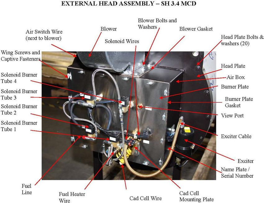
SHC3.4MCD Heater Maintenance.doc Page 2
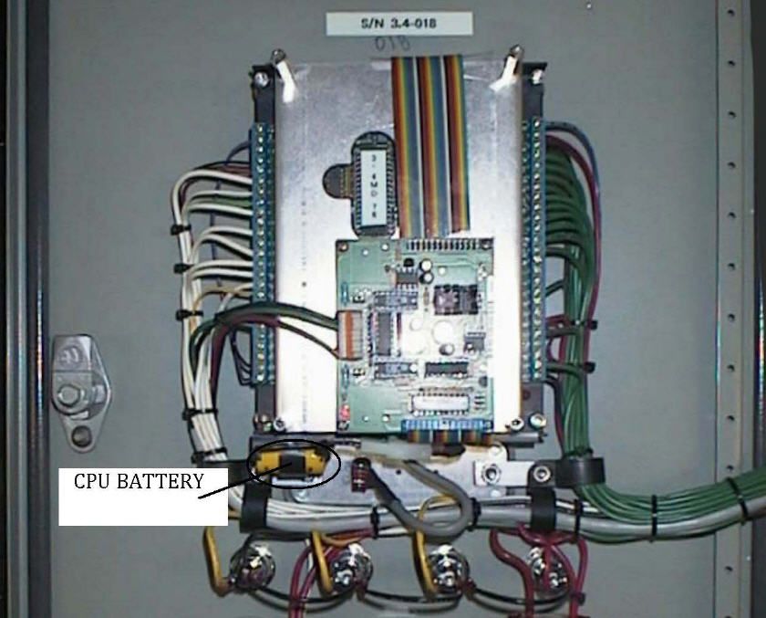
TABLE OF CONTENTS

Maintenance
    1. Introduction ………………………………………………………                               4
    2. Heater Component Description
               Main Heater Components       ………………………………                6
               Burner & Head Assembly Components    ………………              7
    3. Maintenance Schedule          ………………………………………                    8
    4. Record Information ………………………………………………                           11
    5. Visual Inspection      ………………………………………………                       13
    6. Burner Assembly Inspection
               Remove Burner Assembly ………………………………                     14
               Nozzles        ………………………………………………                       16
               Electrodes     ………………………………………………                       17
               Retention ring adjustments ………………………………                 18
    7. Insulation & Coils Inspection
               Front Insulation Inspection ………………………………                19
               Rear Target Inspection       ………………………………               23
               Coil Inspection       ………………………………………                   24
               Reinstall Burner Assembly ………………………………                  25
    8. Component Check
               Blower Speed ………………………………………………                         26
               Fuel pressure ………………………………………………                        28
               Air switch     ………………………………………………                       29
               Flow Sender ………………………………………………                          30
    9. Battery Replacement Procedure
               PK Control Box       ………………………………………...                 31
               BL Control Box       …………………………………………                   32
    10. Run Heater and observe correct operation ………………………             35

Appendix
    A1.    Heater Statistics Form                                      38
    A2.    Fault list                                                  39
    A3.    Setup Data Sheet                                            40
    A4.    Example Insulation Breakdown                                41
    A5.    Inspection Sheet                                            43
    A6.    Collecting the Truck and Heater Info                        44
    A7.    Insulation Packing                     (service Bulletin)   46

SHC3.4MCD Heater Maintenance.doc                                       Page 3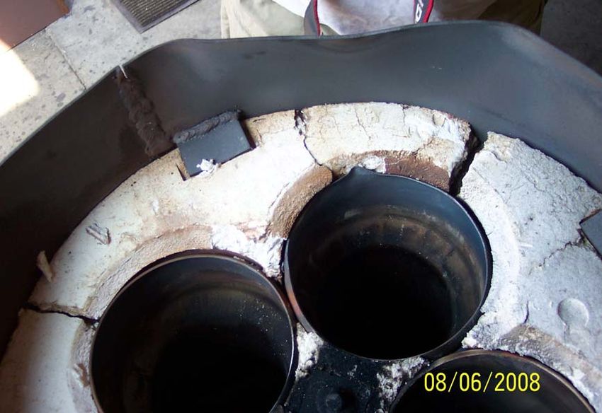
1.0 Introduction

                    SAGE 3.4 Million BTU Glycol Heating System
The SAGE 3.4 Million BTU Glycol Heating System (the system) is a mobile tank-less heater.
The glycol is heated as it flows through the system, and does not retain any glycol internally
except for what is in the heat exchanger coil. The system heats glycol on an as needed base,
shutting the heater safely down when not needed.

The SAGE Heater is a reliable and proven system. SAGE Heaters have been successful in
military and commercial ground support applications for over 30 years. Under normal usage and
annual maintenance, the SAGE Heater will give you many years of superior performance. This
is achieved by using a unique stainless steel alloy heat exchanger core and high quality
manufacturing standards.

The combustion chamber operates under industrial forced draft design principles, with the
exhaust slightly above atmospheric pressure. Heat from the flame is transferred to coils carrying
glycol fluid thru an air / fluid exchange process. The heater operates using diesel fuel for safety.
SAGE Heaters are highly efficient. Utilizing up to 13 stages of heat modulation, the system can
easily meet variable demand requirements by providing superior temperature control. This
results in constant output temperature regardless of input temperature. This is a critical
performance benefit in the de-icing process.

In de-icer truck applications the system is designed for instant heating capabilities. The
advantage of instant heating is that it does not require preheating of the glycol, therefore,
aircrafts can be de-iced in cold climate conditions, quickly and efficiently.

The glycol flows through the system (heat exchanger coils) by means of an external fluid
pumping system. The fluid pumping systems primary purpose is to provide the appropriate fluid
pressure at proper flow rates to successfully de-ice aircraft.

Due to the pump pushing the glycol through the heater exchanger coils, the heater inlet fluid
pressure is greater than the outlet pressure in the heating system (up to the nozzle). The Global
truck design pushes the fluid as pressure drops across each section of the fluid plumbing, which
includes the heater, transport hoses, all fittings and the nozzle.

SHC3.4MCD Heater Maintenance.doc                                                     Page 4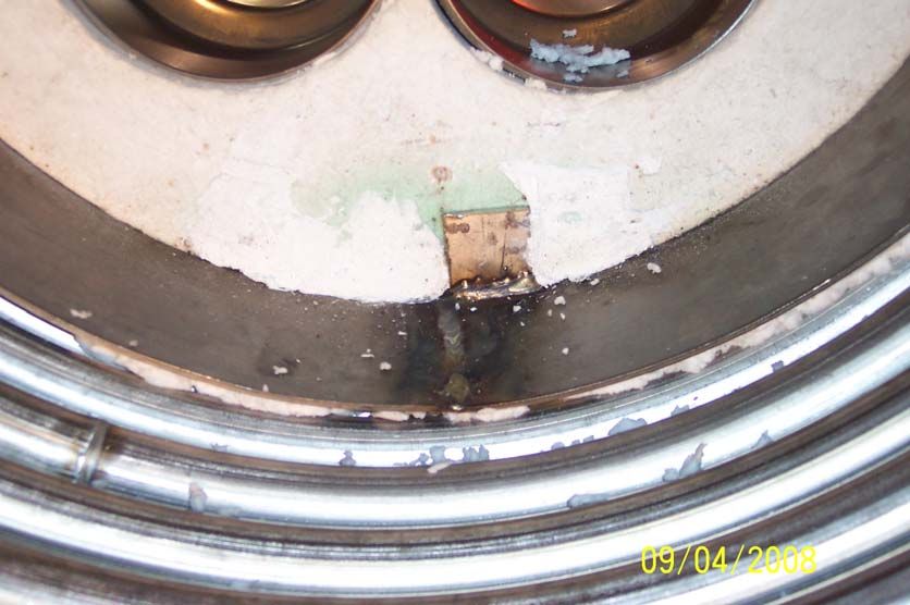
The system is controlled by a DCS (Digital Control System / Heater Control Box). There are
presently two versions of the Heater Control Box. Heaters from SN 9000 to 9949 are designated
the PK series. Heaters from SN 90950 and up are designated the BL Series. The system is
designed around a safety first approach with many operational safety interlock devices. Fluid
flow rates and temperature rates are constantly monitored and used to calculate the required heat
input. When heat is not required the system safely shuts down. When heat is required the
system safely ignites based on the glycol fluid temperature and flow rate.

The SAGE 3.4 Million BTU Glycol Heating System is a mobile on-demand heater. It operates
on an intermittent cycle with 6 levels of safety control. The design intent for this heater was to
provide an on-demand heater for de-icing aircrafts.

    1. If the RTD (Remote Temperature Device) outlet temperature sensor detects 210 °F, the
       heater control box shuts the heater down in an orderly process. The BL series control
       box has a user selectable set point of 200 °F or 210 °F.

    2. Second outlet temperature sensor (preset at 220 °F), which is an input to the controller as
       a safety signal for proper controller shutdown.

    3. Third outlet temperature sensor (preset at 230 °F), which cuts power to the heater.

    4. Stack temperature switch, which is used as a safety shutoff, and cuts power to the heater.

    5. Mechanical Over pressure relief valve at 400 psi on the outlet side.

    6. Air Pressure switch to prove proper combustion air is available

Another important benefit of the DCS is the extensive diagnostic capabilities. This includes
event logging of fault codes for fast and efficient troubleshooting, component status to verify that
each piece of equipment operates correctly, and real time monitoring to see the operational
parameters while the heater is running.

In addition the BL series control box can records these diagnostic parameters to the SD-card for
review or printout on a Windows based computer.

For proper operation and service life it is required that end
of season maintenance be performed annually as per SAGE
heater maintenance schedule.

SHC3.4MCD Heater Maintenance.doc                                                     Page 5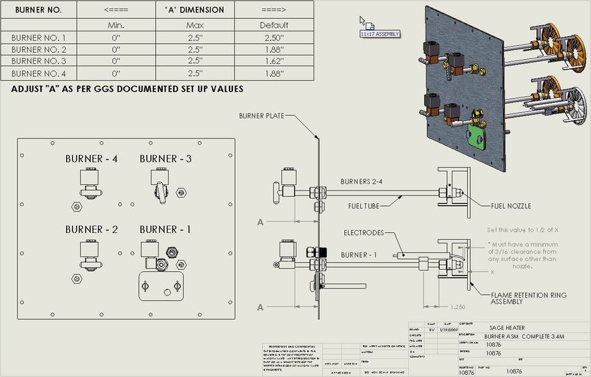
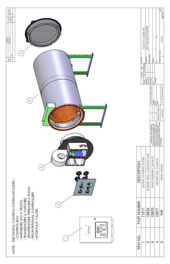
2.1 Main Heater Components

Figure 1

SHC3.4MCD Heater Maintenance.doc   Page 6
2.2 Burner & Head Assembly Components

Figure 2

           Reference Global Parts Manual for associated part numbers

SHC3.4MCD Heater Maintenance.doc                                       Page 7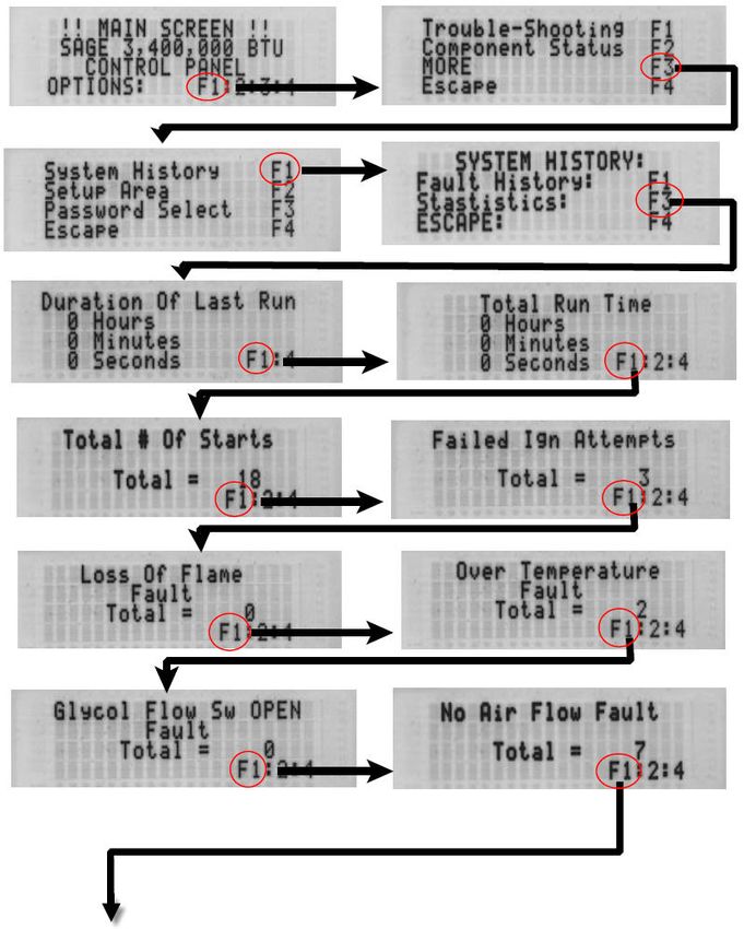
3.0        Maintenance Schedule
                                                                   PERIOD IN HOURS
                        MAINTENANCE
                                                              8   50 100 200    OTHER
         Record statistics at the end of every de-icing
         season.
             • See form A1 at end of this manual. See
 4.1             GGS technical manual procedure – System                       Annually
                 History Statistics (page 30)
             • Measure and record stack temperature each
                 year.

         Visually inspect outside of heater
 5.1        • Look for discolorations and abnormalities.      X                Annually
                See Sect 3.0 Figs. 3 & 4.

         Check heater for leaks
            • Inspect the heater for Hydraulic leaks
 5.2        • Inspect the heater for fuel leaks                   X            Annually
            • Inspect the heater for glycol leaks
            • Inspect the heater inside the truck area.
         Inspect and Clean exhaust screen.
             • Remove the heater exhaust screen and
 5.3            remove any debris and clean with a soft           X            Annually
                wire brush. See Fig. 4.
         Check exhaust duct
            • Inspect exhaust duct for cracks and loose
 5.4           fasteners                                          X            Annually
            • Check for exhaust leaks. See Fig. 1 & 2
         Check blower assembly
            • Inspect blower wheel and housing for
               cracks, deformations, and loose fasteners.
               Be sure inlet cage is securely attached. See
 5.5           Fig. 2                                             X            Annually
            • Check for air leaks at the mounting gasket
               for the Blower and the Burner plate. See
               Fig. 2
         Replace fuel nozzle.
            • Remove burner assembly from burner head
 6.2                                                                  X        Annually
                (see section 6.1)
            • Remove and replace with new nozzles.
         Check ignition electrode gap.
            • See Burner Assembly Adjustment Data on
 6.3            page 6                                                X        Annually
            • Replace electrode if worn beyond
                dimensions. Replace at 200 hours.

  SHC3.4MCD Heater Maintenance.doc                                            Page 8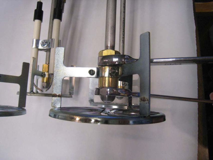
PERIOD IN HOURS
                      MAINTENANCE
                                                          8   50   100   200   OTHER
       Clean carbon buildup from burner assembly
          • Remove the burner assembly from the
              heater Head. Use a soft small wire brush
6.4           to clean any carbon buildup from all the             X           Annually
              parts of the burner. Be careful not to
              damage or misalign any component.
       Check flame retention ring settings.
          • See Burner Assembly Adjustment Data on
6.5           page 6.                                              X           Annually
          • Check that retention rings are securely
              attached and not damaged.

       Check front insulation.
7.1       • See page 10. If the gap is larger than ¼”,             X           Annually
             perform packing procedure.

       Check rear target insulation
       See page 10
7.2                                                                X           Annually

       Inspect for carbon buildup on inner coils
7.3        • Remove with soft wire brush and vacuum                X           Annually
              out.
       Check Blower operation and calibration of Air
       pressure transducer
8.1                                                                X           Annually
           • Use component status
           • Check hydraulic controller
       Check fuel pressure
           • Refer to GGS Technical manual for check
8.2           and adjustment procedure                             X           Annually

       Check fuel controller per GGS Technical manual –
8.3    fuel pressure driver head.                                  X           Annually

       Check air switch operation
8.4    as per Global Ground Support Technical manual               X           Annually

SHC3.4MCD Heater Maintenance.doc                                               Page 9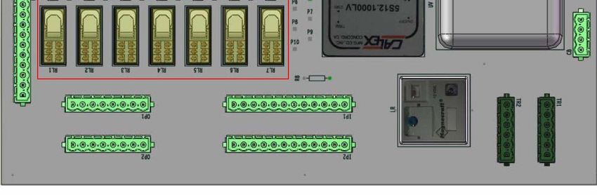
PERIOD IN HOURS
                       MAINTENANCE
                                                             8   50 100 200    OTHER
        Check Flow sender operation as per
        GGS technical manual – flow sender setup
8.5                                                                  X        Annually

        Replace computer backup battery
           • For PK Series go to page 31
9.1                                                                           Annually
           • For BL Series go to page 32

        Replace fuel filter element
           • Fuel filter is located under the heater near
              the outlet manifold, which connects to the
9.2           burner head fuel inlet line.                           X        Annually
           • Disconnect fuel filter and replace with new
              Filter element
        Check the auxiliary engine.
10.1       • Verify that the engine RPM at high throttle         X            Annually
               is per manufactures specifications.

        Check fuel valve solenoid operation as follows:
           • Make sure the fluid tanks are filled with a
               few hundred gallons of cold fluid
           • Turn on the heater. After the heater fires
10.2           look thru the sight glasses and verify that       X            Annually
               all the solenoids (4) have fully turned on
               after each stage fires successively until
               stage 13 is achieved

10.3

 SHC3.4MCD Heater Maintenance.doc                                            Page 10
4.0 Recording Heater information System History (Statistics) -Power up the control box. Follow the sequence of screen shots and record info on Heater Statistics Form in appendix A1. SHC3.4MCD Heater Maintenance.doc Page 11
SHC3.4MCD Heater Maintenance.doc Page 12
5.0           Heater Inspection Areas
Look at the exterior of the Heater and pay special attention to the rear area as noted in figure 8.
Examine all around the back of the Heater where the rear plate bolts to the Heater Body. Also
inspect the front of the Heater in the same location where the front plate bolts to the Heater Body.
Look for discoloration or other abnormalities.

                                      Check 360° around
                                      the Exhaust Duct
                                      for leaks

 Check 360°
 around the Heater
 for abnormalities

                                                                                   Check for signs of
                                                                                   leakage

      Check for signs of
      leakage

   Figure 3 - Back view of Heater

      Check the
      Exhaust
      screen for
      signs of
      debris

      Check the
      Blower
      Assembly &
      Motor for
      signs of
      damage                                                          Check 360°
                                                                      around the Heater
                                                                      for abnormalities

   Figure 4 - Front View of Heater

   SHC3.4MCD Heater Maintenance.doc                                                       Page 13
6.1 Removing the Burner Assembly.
Pull both Burner Assemblies from the Burner Head by:
-Disconnect all the electrical connectors. This includes the
-Cad cell connector
-Fuel Solenoid connectors
-Fuel Heater connector
-Remove the fuel line.
-Remove the ignition wire from the ignition coil.
-Remove the winged thumb screws that hold the burner assembly to the air box.
Slowly pull the burner assembly (see Figure 8) out and place in a safe area. Be
careful to protect the nozzles and the retentions rings from damage and dirt.
Place the burner assembly in a protected area.
Front of
Burner Air Box
Assy.
Cork Front Plate
Gasket
Figure 7
Inspect the cork gasket. Replace if necessary.
Use these directions in reverse to put the burner assembly back. Be careful to align all 4 burners
into the air box when installing.
SHC3.4MCD Heater Maintenance.doc Page 14Back of
Burner
Assy.
Figure 8
Figure 9 shows the inside of the air box. Use a towel or rag to clean each of the burner tubes
inside the air box from any residual diesel fuel. Also clean out any debris that you see in the air
box.
Area 3 Area 4
Area 2
Area 1
Figure 9
SHC3.4MCD Heater Maintenance.doc Page 156.2 Replacing the fuel nozzles.
IMPORTANT: For proper heater operation, nozzles must be
replaced every year or 100 hours.
Clean burner assembly including the fuel nozzle areas. To remove the old nozzles, use two
wrenches (5/8” and 3/4”) and turn counterclockwise (right hand thread) until nozzles are removed.
Replace with new proper nozzles. See picture below.
SHC3.4MCD Heater Maintenance.doc Page 166.3 Electrode Inspections and Adjustment Inspect electrode and verify the following settings as per the drawing below. If the dimensions cannot set, then the electrodes are worn and will need replacement. Figure 6 SHC3.4MCD Heater Maintenance.doc Page 17
6.4        Burner Tube Adjustments
Set the default “A” dimension on the 4 burner’s as stated in the chart in Fig. 4. These dimensions
will allow most heaters to run properly as long as the Air pressure and the Fuel Pressures are
correctly adjusted. The only time you will deviate from these settings are if the fuel is changed, or
it is at a different altitude where adjusting the Blower speeds (Air pressure) cannot get the heater to
perform as expected.

The heater can be adjusted for varying altitudes and fuels thru the Air pressure adjustment (Blower
speed), If this (air pressure adjustment) cannot get the desired results then the next step would be to
adjust the depth of the Burner tubes, In (toward the burner plate) allowing more air and out (away
from the burner plate) allowing less air, All this is in a balance, because the Computer only see the
air pressure reading.

Two Types of Adjustment:             Course which is the “A” Dimension (Mechanical)
                                     Fine which adjusts the actual Air pressure numbers (Software)

Figure 5

  SHC3.4MCD Heater Maintenance.doc                                                      Page 18
7.1 Burner Head Front Insulation Inspection
Using the series of pictures below, inspect the front Burner Head. See next page for procedure.
Note any abnormalities. There is usually some minor marking on the insulation. A typical view is
shown in figure 10. There are two main areas of inspection, the Insulation and the Metal Shield
(Saturn Ring).
Insulation inspection focuses on the white 1-1/2” insulation board inside the Metal shield (Saturn
Ring). No pieces of insulation should be cracked or missing in the center area and outer region.
See appendix A4 for examples of wear and damage.
Inspect the Metal Shield (Saturn Ring). All metal should be intact. No excess distortion should be
seen. If gap between Metal Shield (Saturn Ring) and inner coils is in excess of 1/8” see appendix
A7 for insulation packing procedure.
This is a view of a typical good Burner Head Insulation. This view is looking at a removed Burner
Head on the other side of the air box. You should see this with a mirror and flashlight as depicted
in the following pictures starting with figure 10.
Burner Head Metal Shield
Insulation Burner (Saturn Ring)
(CENTER AREA) Tubes
Inspect this area
Typical 4 places
Burner Head
Insulation missing Insulation
in this area is not (OUTER REGION)
important. Area of inspection
should be 360 deg.
Figure 10
Inspect the rear insulation by looking all the way to the rear of the heater combustion chamber.
Again, there should be no pieces missing or damaged. Slight discoloration is usual as is some
surface cracks of a minor nature.
SHC3.4MCD Heater Maintenance.doc Page 19With Mirror and Flashlight, inspect insulation by inserting mirror thru Burner Tubes and looking at the outer section of the insulation. Look at all the insulation, but pay close attention to the lower region as depicted in figure 9. Figure 11 Figure 12 SHC3.4MCD Heater Maintenance.doc Page 20
Figure 13

 Figure 14
Look at all areas of the back of the Burner Head by moving through the Burner Tubes as
necessary. Note the location of any abnormalities. Use the areas in the picture as designations.
Look for missing sections or deep cracked insulation. See page 13 for examples.

 SHC3.4MCD Heater Maintenance.doc                                                    Page 21
This is a typical picture of a front insulation. See Appendix A4 for examples of damaged
insulation.

If damage is found, then:

         1.       Fill out the Inspection report in appendix A5
         2.       Take photographs of the damage
         3.       Submit inspection report and photographs to your Service provider.

SHC3.4MCD Heater Maintenance.doc                                                   Page 22
7.2 Rear Target Inspection
With the Burner assembly removed use a flashlight to look thru the burner tubes and visually
inspects the rear target. This is a typical picture of the rear target insulation. See Appendix A4 for
examples of damaged insulation.
If damage is found, then:
1. Fill out the Inspection report in appendix A5
2. Take photographs of the damage
3. Submit inspection report and photographs to your Service provider.
SHC3.4MCD Heater Maintenance.doc Page 237.3 Coil Inspection
Inspect the coils for excessive carbon buildup. Clean as required. Only use a soft brush to loosen
carbon and vacuum out.
Note. Be careful when cleaning as to not damaging the front and rear insulation materials.
If damage is found, then:
1. Fill out the Inspection report in appendix A5
2. Take photographs of the damage
3. Submit inspection report and photographs to your Service provider.
SHC3.4MCD Heater Maintenance.doc Page 247.4 Reinstall Burner Assembly
Use section 6.1 in reverse to re-install the burner assembly.
Before installing Burner assembly check the following:
1. Mating surfaces are clean
2. Gasket is on good shape
3. All fasteners and hardware are in place.
Carefully slide in Burner assembly. DO NOT FORCE
SHC3.4MCD Heater Maintenance.doc Page 258.1 Blower Operational Check
Setup (start air speed)
Stage 14 is the starting blower stage. It must be adjusted via air pressure reading to give a shaft
speed of 1600 +/- 50. The shaft speed will need to be measured by a tachometer
Select an air pressure (shown by A) to achieve a blower shaft speed of 1600 rpm. When this is
achieved, then set the pressure (shown by B)
SHC3.4MCD Heater Maintenance.doc Page 26Blower Signal Test. The signal is from 0 to 4095, Blower shaft speed is from 400 to 5000 RPM. Use photo tachometer to verify the low and high blower speed. SHC3.4MCD Heater Maintenance.doc Page 27
8.2 Fuel System Operational Check

 Toggle the fuel pressure signal from low to high (signal 0 – 5000)

 Low is approximately 75 psi
 High is approximately 300 psi

 If fuel pressure does not go thru full range then recalibrate per Global fuel setup procedure.

 SHC3.4MCD Heater Maintenance.doc                                                    Page 28
8.3 Air Switch Component Check
 Switch should be open below 1000 rpm and closed above 1000 rpm

 SHC3.4MCD Heater Maintenance.doc                                 Page 29
8.4 Flow Sender Component Check

 Toggle to any screen, such as below, that displays fluid flow (F). This should be approximately
 50-60 gallons / minute at approximately 200 psi

 SHC3.4MCD Heater Maintenance.doc                                                 Page 30
9.0    Change Battery

         Removal of the battery from the PK digital control system will result in
                                          Loss of Data

 In order to avoid the loss of user-entered values such as: flow sender calibration, air pressure
 settings, fault history & statistics use the following procedure
 As a precaution, all user-entered settings should be recorded in the event that the data is lost.
 Supply power to the control box and be sure the computer is powered. This may be verified by
 observing the display located on the front of the control box. If any message is displayed, the
 computer is powered.
 While maintaining this power, unplug the old battery and replace it with the new battery. The
 system voltage will maintain the memory while the battery is being exchanged.

                                            CAUTION
 Care should be taken when working on the system while power is applied.

 SHC3.4MCD Heater Maintenance.doc                                                     Page 31
BL Backup Battery Replacement & System Information Procedure:
STEP 1: Download System Information to the SD-card from Heater Control System.
1) Power down the heater control system.
2) Insert the SD-card into the card bay, push in all the way till the bay holds the cards.
3) Power up the system again.
4) Go to "Setup Area"
5) Go to the following screen option (Screen #1). Press F2 on the screen:
Screen #1
********************
!! Setup Area !!
Dn=F1 !Scroll! Up=F4
Data Operations F2
Flow Switch S.P. F3
********************
6) The application will display the following screen option (Screen #2). Please press F2 on the
system keypad to go to Create Logs screen option:
Screen #2
********************
Data Operations
F2 Data To/From SD
F3 Log Operations
ESCAPE: F4
********************
7) At this screen the user may download the information to the sd-card. Pressing F2 will
download the system information to the sd-card from the heater control system (Screen #3).
Screen #3
********************
System Information
Press F2 to Download
Press F3 to Upload
ESCAPE: F4
********************
8) As the information is being saved on the sd-card the system will display the following
message (screen #4). Once the operation is completed the system will revert to the Main
Screen.
Screen #4
********************
Performing file
operations, please
wait till the Main
screen displays
********************
SHC3.4MCD Heater Maintenance.doc Page 32STEP 2: Replace Backup Battery on Main board located inside the Heater Control
Enclosure. Refer to the BL Parts list Document for location and PN.
9) Remove the power, by pressing E-STOP button on the system.
10) Remove the metal protective cover off the Main board.
11) Now locate the backup battery on the Main board, and un-hinge the battery from the battery
holder.
12) Place a new battery on top of the batter holder and push the battery in the battery holder.
13) Place the metal protective cover back on the Main board.
STEP 3: Upload System Information from the SD-card to the Heater Control System.
14) Power up the heater control system.
15) Go to "Setup Area"
16) Go to the following screen option (Screen #5). Press F2 on the screen:
Screen #5
*********************
!! Setup Area !!
Dn=F1 !Scroll! Up=F4
Data Operations F2
Flow Switch S.P. F3
*********************
17) The application will display the following screen option (Screen #6). Press F2 on the system
keypad to go to Create Logs screen option:
Screen #6
*********************
Data Operations
F2 Data To/From SD
F3 Log Operations
ESCAPE: F4
*********************
18) At this screen the user may upload the information to the system. Pressing F3 will upload the
system information from the SD-card to the heater control system (Screen #7). Once the
operation is completed the system will revert to the Main Screen.
Screen #7
********************
System Information
Press F2 to Download
Press F3 to Upload
ESCAPE: F4
********************
SHC3.4MCD Heater Maintenance.doc Page 33List of Errors:
1) If the following error screen appears:
" Data Logging "
" File Operation "
" Failed "
Check that a properly formatted SD-card is in the bay.
Reboot or Re-Power Up the Heater Control System. Perform the operation again.
SHC3.4MCD Heater Maintenance.doc Page 34Run Heater and observe correct operation Description of Heater startup Upon closure of the Power Switch, the CPU and Display are powered up. Upon closure of the Heater Switch, the CPU goes thru a switch check. At the end of the switch check, the CPU activates the Blower, the Heater Enabled Light, and the Fuel Heater. At this time a pre-purge countdown begins. Two thirds thru the Pre-purge the Ignition and Fuel Pump are activated. At the end of the Pre-purge the Fuel Solenoid #1 is energized (Stage-14). Upon sighting a flame inside the heater, the CPU continues thru a ramp up cycle, this includes energizing the Flame On Light, and ramping up the air, then fuel, to the next run up stage (Stage-1), then (Sage -5), then (Stage-8), then (Stage-11), then (Stage-12), then (Stage-13) (See Heater Spooling Up Operation below for more detail). At this point the CPU controls the heat output, to a predetermined temperature, thru fuel pressure and the number of fuel solenoids that are energized. In addition all inputs are monitored with safety being the first concern and temperature control being the second. Upon reaching the predetermined outlet temperature the CPU stages down the heater until Stage 1. After this, the inlet temperature of 180 °F or the user selected temperature will be reached turning off the heater and all outputs except the Blower and Heater Enabled Light. A post-purge cycle then begins. At the end of the post-purge cycle, the CPU turns off the Blower control and Heater Enabled light. Heater Spooling Up Operation When the heater spools up, it lights off at stage 14 then to stage 1 increasing the fuel pressure to 200psi and air pressure with nozzle 1 open. After stage 1 if needed, the heater will spool up to stage 5 leaving the fuel pressure the same (200psi) and leaving nozzle 1 open, increasing the air pressure and opening nozzle 2. If needed the heater will spool up to stage 8 leaving the fuel pressure the same (200psi) nozzles 1 & 2 open increasing the air pressure and opening nozzle 3. If needed, the heater will spool up to stage 11 leaving the fuel pressure the same (200psi), nozzles 1,2, & 3 open , increasing the air pressure and opening nozzle 4. If needed, the heater will spool up to stage 12 increasing the fuel pressure to 250psi, nozzles 1, 2, 3, & 4 open and increasing the air pressure. If needed, the heater will spool up to stage 13 increasing the fuel pressure to 300psi, nozzles 1, 2, 3 & 4 open and increasing the air pressure. If the maximum stage is not needed, the heater will only spool up to the stages needed to give outlet temperature of 180 + / -5. Refer to the heater stage values in chart in appendix A3. To manually check the Maximum blower speed, Turn the override knob fully clockwise, the blower should reach Max speed typically 5,000 RPM. Adjustment is required if either the Fuel or Blower control heads are replaced Adjustment is required after replacing either the fuel or blower electrical control heads. SHC3.4MCD Heater Maintenance.doc Page 35
Detailed heater operation by view of relay bank. PK Series Only

Open the control box and locate the relay bank as seen below.

                  Relay 09

                  Relay 01

                  Relay 02

                  Relay 03

                  Relay 04

                  Relay 05

                  Relay R2

                  Relay 07

                  Relay 06

                  Relay 010

                  Relay 08

    With the fluid temperature at ambient temperature, Turn on the heater and observe the
    operation as indicated under Heater turn-on sequence. View all the site glasses and observe
    that all burner tubes ignite when they are supposed to.

SHC3.4MCD Heater Maintenance.doc                                                 Page 36
Heater start sequence for the SAGE 3.4M Heater (PK Series).
1. Heater enable light (Relay 08) comes on at the beginning of the cycle and stays on until
the heater is fully shut off
2. Next the Fuel Heater (Relay 010) is energized and will stay on approximately 3 minutes
after the flame is detected.
3. Next the Exciter (Relay 02) is energized and will stay on until a flame is detected.
4. Next the Fuel pump (Relay 03) is energized and will stay on during the heating operation.
5. Next the Fuel 1 Solenoid (Relay 04) is energized. They stay on dependent on the stage
that the computer set due to heat requirements.
6. Next the Flame on Light (Relay 09) is energized and stays on until the flame is
extinguished.
7. Next the Fuel 2 Solenoid (Relay 05) is energized. They stay on dependent on the stage
that the computer set due to heat requirements.
8. Next the Fuel 3 Solenoid (Relay R2) is energized. They stay on dependent on the stage
that the computer set due to heat requirements.
9. Next the Fuel 4 Solenoid (Relay 07) is energized. They stay on dependent on the stage
that the computer set due to heat requirements.
10. Next At Temp Light (Relay 06) is energized when the heater has reach the requested
temperature.
11. The Fault light (Relay 01) will not turn on under normal conditions. If a fault occurs than
this light will turn on.
SHC3.4MCD Heater Maintenance.doc Page 37Detailed heater operation by view of relay bank. BL Series Only The picture below shows the Printed Circuit Board with the relay bank outlined by the red box. When the associated LED is on the relay is energized. SHC3.4MCD Heater Maintenance.doc Page 38
Heater start sequence for the SAGE 3.4M Heater (BL Series).
1. Heater enable light (RL1) comes on at the beginning of the cycle and stays on until the
heater is fully shut off
2. Next the Fuel Heater (RL2) is energized and will stay on approximately 3 minutes after
the flame is detected.
3. Next the Exciter (RL3) is energized and will stay on until a flame is detected.
4. Next the Fuel pump (RL4) is energized and will stay on during the heating operation.
5. Next the Fuel 1 Solenoid is energized. They stay on dependent on the stage that the
computer set due to heat requirements.
6. Next the Flame on Light (RL5) is energized and stays on until the flame is extinguished.
7. Next the Fuel 2 Solenoid is energized. They stay on dependent on the stage that the
computer set due to heat requirements.
8. Next the Fuel 3 Solenoid is energized. They stay on dependent on the stage that the
computer set due to heat requirements.
9. Next the Fuel 4 Solenoid is energized. They stay on dependent on the stage that the
computer set due to heat requirements.
10. Next At Temp Light (RL6) is energized when the heater has reach the requested
temperature.
11. The Fault light (RL7) will not turn on under normal conditions. If a fault occurs than this
light will turn on.
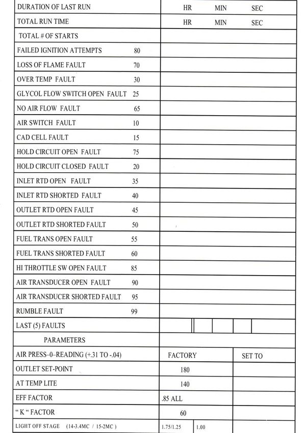
SHC3.4MCD Heater Maintenance.doc Page 39A1. Heater Statistics Form (PK Series) (as per section 4.1) SHC3.4MCD Heater Maintenance.doc Page 40
A2.       Fault List (PK Series)

10      Indication that air switch is closed when it should be open.
        (EVEN IF THE HEATER HAS NOT BEEN TURNED ON YET)
15      Indication that cad cell circuit is closed when it should be open.
        (FLAME SIGHTED BEFORE HEATER RUNNING OR AFTER
        HEATER TURNED OFF)
20      Indication that hold contact circuit is closed when it should be open.
25      Indication that glycol flow is less than 20 G.P.M. for 5 seconds or more.
        (AFTER HEATER HAS BEEN TURNED ON)
30      Indication that outlet temperature has exceeded set point of mechanical
        over temperature switch lower setting. (Upper setting and stack switch are
        wired in series, and will cut the power to the heater control relay coils.)
        Lower limit should be set at 225degress F, Upper limit should be set at
        235 degrees F, and Stack switch is factory set at 1400 degrees F.
35      Indication that Inlet RTD circuit is open or indicated temperature is higher
        then__400 °F__.
40      Indication that Inlet RTD circuit is closed /shorted or indicated temperature
        is lower then __100 °F __.
45      Indication that Outlet RTD circuit is open or indicated temperature is higher
        then__400 °F __.
50      Indication that Outlet RTD circuit is closed /shorted or indicated
        temperature is lower then __100 °F __.
55      Indication that Fuel pressure transducer circuit is open or indicated pressure
        has exceeded __500__ psi.
60      Indication that Fuel pressure transducer circuit is closed /shorted or
        indicated pressure has exceeded lower limit (6 psi).
65      Indication that air switch circuit is open when it should be closed.
70      Indication that cad cell circuit is open when should be closed (loss of flame
        after heater has been running)
75      Indication that hold contact circuit is open when it should be closed .
        (Under volt relay open or CB-5 open also trips this fault code)
80      Indication that heater failed to ignite during a normal attempt to start.
85      Indication that there is no input to the hi-throttle circuit of the computer.
        (Currently this circuit is also thru the fluid level circuit of the deicer.)
90      Indication that the Air pressure transducer has a open control circuit.
95      Indication that the Air pressure transducer has a shorted/closed control
        circuit.

SHC3.4MCD Heater Maintenance.doc                                          Page 41
A2. Fault List (BL Series)
10 Indication that air switch is closed when it should be open.
(EVEN IF THE HEATER HAS NOT BEEN TURNED ON YET)
15 Indication that cad cell circuit is closed when it should be open.
(FLAME SIGHTED BEFORE HEATER RUNNING OR AFTER
HEATER TURNED OFF)
20 Indication that hold contact circuit is closed when it should be open.
25 Indication that glycol flow is less than 20 G.P.M. for 5 seconds or more.
(AFTER HEATER HAS BEEN TURNED ON)
30 Indication that outlet temperature has exceeded set point of mechanical over
temperature switch lower setting. (Upper setting and stack switch are
wired in series, and will cut the power to the heater control relay coils.)
Lower limit should be set at 225degress F, Upper limit should be set at
235 degrees F, and Stack switch is factory set at 1400 degrees F.
35 Indication that Inlet RTD circuit is open or indicated temperature is lower
then__-100 °F__.
40 Indication that Inlet RTD circuit is closed /shorted or indicated temperature
is higher then __400 °F __.
45 Indication that Outlet RTD circuit is open or indicated temperature is lower
then__-100 °F __.
50 Indication that Outlet RTD circuit is closed /shorted or indicated
temperature is higher then __400 °F __.
55 Indication that Fuel pressure transducer circuit is open or indicated pressure
is lower than __-6__ psi.
60 Indication that Fuel pressure transducer circuit is closed /shorted or
indicated pressure has exceeded high limit (500 psi).
65 Indication that air switch circuit is open when it should be closed.
70 Indication that cad cell circuit is open when should be closed (loss of flame
after heater has been running)
75 Indication that hold contact circuit is open when it should be closed .
(Under volt relay open or CB-5 open also trips this fault code)
80 Indication that heater failed to ignite during a normal attempt to start.
85 Indication that there is no input to the hi-throttle circuit of the computer.
(Currently this circuit is also thru the fluid level circuit of the deicer.)
90 Indication that the Air pressure transducer has a open control circuit.
95 Indication that the Air pressure transducer has a shorted/closed control
circuit.
SHC3.4MCD Heater Maintenance.doc Page 42A3. Set-up Data Sheet
Air
Solenoids Fuel Fuel Press Blower
Stage Active Press Flow (wc) RPM
AIR SW TRIP 0 0 1000-1200 AIR SW
14 (light off) #1 150 6 1.25 " 1550
1 #1 200 7.1 3.50 " 2700to3100
2 #1 250 7.91 4.50 " 2900to3400
3 #1 300 8.66 5.50 " 3300to4000
4 #1 & 2 150 12 6.75 " 3400to4100
5 #1 & 2 200 14.1 7.00 " 3600to4200
6 #1 & 2 250 15.81 7.10 " 3700to4300
7 #1 & 2 300 17.32 7.50 " 3900to4400
8 #1 & 2 & 3 200 21.2 8.10 " 4000to4500
9 #1 & 2 & 3 250 23.72 8.25 " 4100to4600
10 #1 & 2 & 3 300 25.98 8.50 " 4300to4700
11 #1 & 2 & 3 & 4 200 28.2 9.00 " 4600to4800
12 #1 & 2 & 3 & 4 250 31.62 10.00 " 4700to4900
13 #1 & 2 & 3 & 4 300 34.64 10.50 " 4900to5000
15 (post purge) 0 0 9.00 "
16 (post purge) 0 0 5.00 "
Starts stage 14,then adjusts air and then fuel to stage1, then to stage 5, then to stage 8 Then to
stage 11, then to stage 12 then to stage 13, after that , the heater targets to the
Outlet set point adjusting the stages. Air leads the fuel going up, fuel leads the air going down.
SHC3.4MCD Heater Maintenance.doc Page 43A4. Insulation Breakdown Examples Insulation is cracked thru The above damage can be repaired with insulation putty The above picture is damaged beyond repair. SHC3.4MCD Heater Maintenance.doc Page 44
Continued

Example of warped metal shield (Saturn ring). Follow packing procedure in appendix A7

If a heater is identified to have Saturn Ring distortion is in excess of 1” there should be further
inspection and images made with a digital camera to determine if the Saturn Ring Insulation
component is broken. If the Saturn Ring Insulation appears to be broken beyond mild cracking
the Wet Blanket Insulation Kit should not be installed.

SHC3.4MCD Heater Maintenance.doc                                                   Page 45
A5. Inspection Sheet
                                       Inspection Sheet
DATE of Inspection                 _______/_____/______

Airport                            ________________________________

Customer                           _________________________________

Contact Person ______________________ Phone _____-______-______X______

Truck and Heater Data
The following to be found on the Global ID Plate (Located on Boom Pedestal in rear heater compartment of truck)

Deicer Manufactured Date____/____/_____ Deicer Serial Number_____________________

The following to be found in the truck cab

Deicer Truck Aux Engine Hours (from the hour meter)                           ______________

The Serial number is found using figure 3

Heater Serial Number               ____________________

The following to be found in the Heater control box in the right/rea of the heater
compartment. See figure 5. If no hour meter exists, pull hours from the computer screen.

Heater Hours (from the hour meter) _____________________

                                           Inspection Information
Heater general appearance, especially the rear and front of the Heater_____________________

_____________________________________________________________________________

Burner Head insulation (Outer Region) inspection results _______________________________

_____________________________________________________________________________

Metal Shield Ring inspection results_______________________________________________

_____________________________________________________________________________

Gap Measurement _____________________________________________________________

    Please take digital pictures of suspected damaged areas.
Inspected by _________________

SHC3.4MCD Heater Maintenance.doc                                                               Page 46
A6. Collecting the Truck and Heater Info
Location of the Truck Serial Number is in the rear of the truck on the Boom
Pedestal.
Truck
Serial
Number
Heater
Figure 1
Next get the Truck Auxiliary Engine Hours inside the truck cabin. The hour meter
is on the control panel to the right of the drivers seat. Record the Heater Serial
Number. The location of the Serial number is shown below.
Serial
Number
Figure 2
SHC3.4MCD Heater Maintenance.doc Page 47Location of the Heater Hour meter is in the Heater Control Box (Select PK Series
only) in the rear of the truck. Record the reading.
Heater
Hour Meter
Figure 3
On the BL Series use the Display screen and keypad to retrieve the hour meter
information in the statistics page.
SHC3.4MCD Heater Maintenance.doc Page 48A7. Insulation Packing
The following Service Notification is published to address the sealing condition between
the high and low pressure zones of the Sage Heater – SCH 3.4 MDC Heater. A post
production upgrade has been developed to improve the seal of the heater head
assembly with the inner fluid coil. It has been determined that this can improve the
longevity and efficiency of the heater. Under certain conditions it will also prevent a
premature break down of the existing head assembly insulation components.
Kit contents and instructions are as follows;
CONTENTS:
1. 1 Section of Wet blanket
TOOLS REQUIRED:
Digital Camera, 9/16 in wrench, 7/16 in wrench, wire cutter (flush),
Small adjustable wrench, duck bill pliers, sharp utility knife, wire ties and soft brush
PROCEDURE:
1. REMOVE BURNERS
1.1 Remove wire ties on solenoid wiring; remove exciter cable at exciter (careful with
inner cable)
1.2 Disconnect fuel solenoid wires, disconnect fuel heater wires, and disconnect cad
cell wiring.
1.3 Disconnect fuel line at solenoid #2, remove 16 wing screws, loosen burner plates
from air box
1.4 Remove burner plate fasteners and Remove burner heads.
SHC3.4MCD Heater Maintenance.doc Page 492. INSPECTION
1.1 Identify any excess space between the Saturn Ring and the Inner Fluid Coil.
Inspect 360 degrees around. This can be done with a 1/8” welding rod or with a
shim of a known thickness (1/8”).
1.1.1 Gaps in excess of 1/8” should be addressed with the Insulation Kit. IF
this condition exists proceed with the following procedure.
1.2.1 If a substantially deformed Saturn Ring and or Broken Burner Head
Insulation is identified during this procedure, e-mail digital photos to
and contact Maloya Laser.
3. WET BLANKET INSTALLATION
3.1 If possible, remove any insulation debris from the area between the Saturn Ring
and Inner Fluid Coil and in front of this area. This is to minimize old pieces of
insulation from interfering with the insertion of the Wet Blanket.
3.2 Pinch a leading edge of the Insulation to a point to aid in insertion.
SHC3.4MCD Heater Maintenance.doc Page 503.3 Position Wet Blanket in front of Saturn Ring (A) and slide and compress as much
as possible into the opening by hand or with a blunt tool, This will take approx.
10-20 Minutes (B). Trim off any excess with utility knife (C) Repack any loose
material and remove left over cut pieces (D).
(A) (B)
(C) (D)
SHC3.4MCD Heater Maintenance.doc Page 51(E) View of completed Wet Blanket Installation
3.4 Air Dry for 24 hours prior to operation. If operating the heater with in a few days
of this procedure, cycle on and off several times to fully dry out material.
SHC3.4MCD Heater Maintenance.doc Page 52You can also read