Truly-Optimized PWR Lattice for Innovative Soluble-Boron-Free Small Modular Reactor
←
→
Page content transcription
If your browser does not render page correctly, please read the page content below
Truly-Optimized PWR Lattice for Innovative Soluble-
Boron-Free Small Modular Reactor
Xuan Ha Nguyen
Korea Advanced Institute of Science and Technology
Seongdong Jang
Korea Advanced Institute of Science and Technology
Yonghee Kim ( yongheekim@kaist.ac.kr )
Korea Advanced Institute of Science and Technology
Research Article
Keywords: ATOM, Centrally-Shielded Burnable Absorber (CSBA), Soluble-Boron-Free (SBF), Disk-type
Burnable Absorber (DiBA), TOP (Truly Optimized PWR) lattice, Small Modular Reactor (SMR)
Posted Date: March 1st, 2021
DOI: https://doi.org/10.21203/rs.3.rs-264089/v1
License: This work is licensed under a Creative Commons Attribution 4.0 International License.
Read Full License
Page 1/29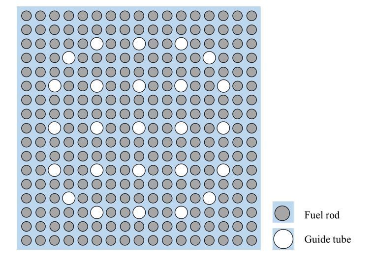
Abstract
A novel re-optimization of fuel assembly (FA) and new innovative burnable absorber (BA) concepts are
investigated in this paper to pursue a high-performance soluble-boron-free (SBF) small modular reactor
(SMR), named autonomous transportable on-demand reactor module (ATOM). A truly optimized PWR
(TOP) lattice concept has been introduced to maximize the neutron economy while enhancing the
inherent safety of an SBF pressurized water reactor. For an SBF SMR design, the 3-D centrally-shielded BA
(CSBA) design is utilized and another innovative 3-D BA called disk-type BA (DiBA) is proposed in this
study. Both CSBA and DiBA designs are investigated in terms of material, spatial self-shielding effects,
and thermo-mechanical properties. A low-leakage two-batch fuel management is optimized for both
conventional and TOP-based SBF ATOM cores. A combination of CSBA and DiBA is introduced to achieve
a very small reactivity swing (
coefficient. Consequently, the temperature defect between hot-full-power (HFP) and cold-zero-power (CZP)
conditions becomes smaller, requiring smaller CR worth.
For a successful SBF operation, it is crucially important to minimize the excess reactivity with BAs so that
the criticality can be well controlled by using weak control rods. This paper is concerned with an SMR,
named Autonomous Transportable on-demand Reactor Module (ATOM), which is currently under
development at Korea Advanced Institute of Science and Technology (KAIST) in Korea. For the ATOM
core, a newly optimized FA design, so-called TOP (Truly-Optimized PWR) lattice, has been developed to
improve both neutron economy and safety of the core. In addition, a new combination of innovative BAs
is proposed to assure sufficiently small excess reactivity, e.g., < 1,000 pcm, for the ATOM. Details of the
TOP design and ATOM core optimizations are discussed in the paper.
In this work, the Monte Carlo Serpent 2 [7] with the nuclear library ENDF/B-VII.1 is mainly used for the
neutronics calculations. Meanwhile, a multi-physics core calculation is also performed by a two-step
Serpent-COREDAX [8] system.
2. Innovations For Soluble-boron-free Small Modular Reactor.
2.1. The Truly-Optimized PWR Lattice
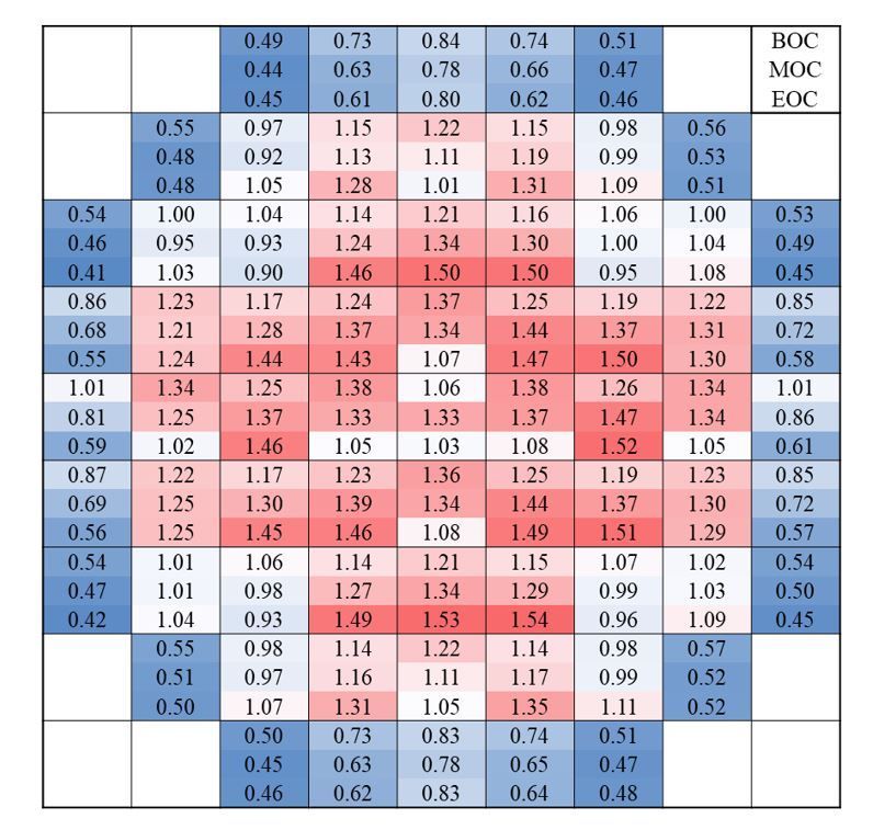
Figure 1 depicts the typical 17×17 PWR FA and its detailed dimensions and specifications are given in
Table I [9]. The average coolant and fuel temperatures are taken from typical PWR designs. It should be
noted that the HTU ratio is about 4.1. It is mentioned that other commercial FA designs such as Korean
APR1400 [10] have a similar HTU ratio.
Based on the typical FA design, there are two ways to enhance the HTU ratio to improve the neutron
economy. The first one is to reduce the fuel rod diameter or the number of fuel rod per FA while preserving
the FA and active core size. However, fuel inventory per FA can be reduced significantly in this case,
consequently the cycle length may be reduced unacceptable, which outweighs the improved neutron
economy due to enhanced moderation [6]. In addition, a new fuel pellet needs to be developed in the case
of the reduced fuel diameter. On the other hand, the second way is to enlarge the pin pitch while
preserving the fuel rod dimension. Thus, the FA and active core sizes become slightly bigger in the radial
direction. In this paper, the modification on the pin pitch is concerned to assess the TOP design, as
thermal and mechanical performances of the standard fuel rod are rather well validated under the
standard PWR conditions. Moreover, for the existing PWRs, the first approach is possible as the core size
is fixed. Meanwhile, for the new reactor design like ATOM, both of the two options are possible. However,
the second way is adopted to minimize the fuel rod design changes.
In order to select a TOP design for an SBF SMR, several objectives must be taken into account:
Maximization of the neutron economy
Sufficiently & appropriately negative MTC and fuel temperature coefficient (FTC)
Page 3/29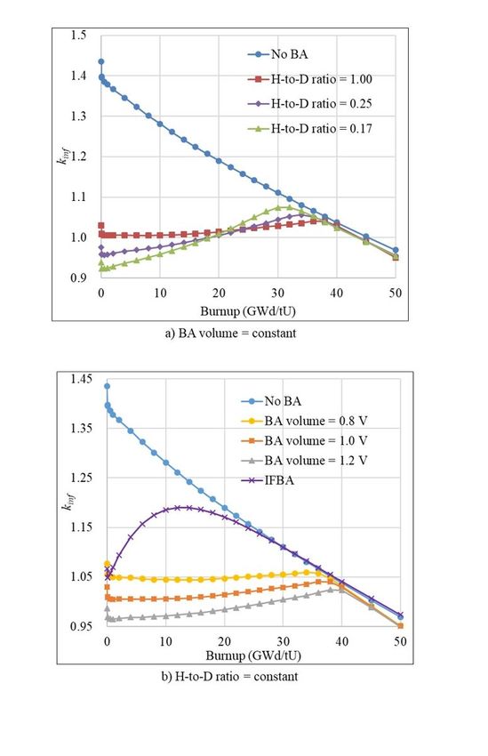
Minimization of the temperature defect for improved CR worth margin
     Maintenance of the clad-to-coolant heat transfer characteristics
     Acceptable size of FA

To find an optimal pitch for the typical FA design, a parametric study has been performed for a 2-
dimensional infinite array of the FA using the Serpent code. The pin pitch is adjusted to obtain various
HTU ratios and Fig. 2 shows the infinite multiplication factor (kinf) with respect to the HTU ratio at zero
burnup for two fuel enrichments and boron concentrations. In the Serpent calculations, 300 active and
100 inactive cycles are used with 100,000 histories per cycle, resulting in about 5.0 pcm uncertainty of the
kinf values.

One can clearly notice in Fig. 2 that the typical FA design is quite under-moderated due to the soluble-
boron and the neutron economy is far from the optimal condition for the two commercial enrichment
regardless of the boron. For the 5.0 w/o case, the optimal HTU ratio is about 9.0. Consequently, the kinf
value can be increased quite substantially by increasing the HTU value in an SBF core. In the commercial
PWRs, the fuel lattice is quite under-moderated mainly due to potentially positive MTC at hot-zero-power
(HZP)-BOC condition requiring a high boron concentration [10]. In the TOP approach, the HTU value
should be determined such that the MTC should be sufficiently and appropriately negative over the whole
cycle with an acceptable FA size, and the fuel utilization should be enhanced. It is important to recall that
the HTU ratio should not be too close to the optimal condition in Fig. 2 since the MTC will be quite small
or close to zero.

To quantify benefit of the TOP design in terms of fuel burnup, non-poisonous FA with 4.95 w/o U was
depleted using Serpent and the burnup-dependent kinfvalues are plotted in Fig. 3 for a few HTU values.
One standard deviation of the kinf values in Fig. 3 is about 10 pcm. In the FA depletion, specific power
density of the ATOM core is used, i.e., 26 W/gU [5]. One can notice that the BOC kinf clearly increases
when HTU increases from 4.1 to 7.0. However, after a certain burnup, the behavior of kinfis inversed, which
is due to smaller buildup of Pu-239 and higher fission product poisoning in a softer spectrum.

In order to investigate the cycle length and discharge burnup for a two-batch fuel management (FM), a
linear reactivity model [11] is used and the results are given in Table II, in which it is assumed that neutron
leakage is 7,000 pcm. One can see that the cycle length and discharge burnup increase noticeably with a
slight increase in the HTU ratio from the reference one. It should be noted that the fuel burnup is rather
maximized with the HTU ratio of ~5.7, about 3% higher than the reference case, and then it even
decreases with further increasing HTU ratio beyond 5.7. One also observed that the FA size increases by
about 10% for HTU=5.7, which will lead to a ~10% bigger core size. Therefore, the HTU can be increased
up to ~5.7 for the TOP design if the 10% larger FA is acceptable in the core design.

Figure 4 shows a neutron spectrum comparison for several HTU ratios at two burnup points. It can be
seen that the spectrum becomes softened with bigger HTU ratio. In particular, the spectrum is much
softer with HTU=7.0 and this enhances fission product poisoning leading to a lower fuel burnup. In
                                                   Page 4/29
addition, it is important to note that 100% mixed-oxide (MOX) core is likely to be feasible as the
significantly softer spectrum of the TOP design, an enhanced-moderation design, can resolve problems
caused by the spectrum hardening due to Pu isotopes [12] [13] [14].

In Fig. 5, power peaking factor (PPF) in the FAs for various HTU values is plotted as a function of burnup.
One can notice that PPF decreases with burnup for all cases and the maximum value is about 1.08 at 0
GWd/tU. It is also observed that a larger HTU ratio results in a similar or slightly smaller PPK than that of
the reference one regardless of burnup. It is because the impact of water-filled guide tube on PPF is less
significant as the neutron spectrum becomes softer with a higher HTU ratio. The associated uncertainty
of the PPF is about 0.5% in this analysis.

The most important parameters for the inherent safety of the core are temperature coefficients, FTC and
MTC, which must be always negative at any condition. Nevertheless, too much negative temperature
coefficients are not always preferable, such as a strongly negative MTC at EOC condition (e. g., -63
pcm/K) results in a large control worth requirement [5]. In addition, a less negative FTC reduces the
deviation of inlet coolant during an autonomous operation [15]. It is recommended that the MTC should
be around -30.0 pcm/K and the FTC should be about -2.0 pcm/K for a successful passive frequency
operation [15]. The FTC and MTC values for various HTU ratios at HFP condition are listed in Table III.
One can notice that temperature coefficients become less negative with increased HTU ratio due to the
softener neutron spectrum, while they are more negative with burnup due to Pu-239 and fission poisoning
buildups. The optimal HTU ratio for autonomous operation is around 5.7 as the FTC is about -2 pcm/K
and the MTC is around -30 pcm/K. The associated uncertainties of FTC and MTC are 0.14 pcm/K and 0.8
pcm/K, respectively. It is assumed that temperature coefficients are linear functions of temperature in this
evaluation.

The reactivity difference between HFP and CZP conditions is defined as temperature defect, which is
compensated by CR insertion to obtain CZP condition. Temperature defects from HZP to HFP for various
HTU ratios and fuel burnups are tabulated in Table IV. As expected, it decreases significantly with
increased HTU ratio since temperature coefficients are smaller with a higher HTU ratio as shown in Table
III. It is advantageous that a smaller shutdown rod worth is required for a larger HTU ratio. In addition, CR
radius can be enlarged with a higher HTU ratio to enhance the CR worth further. The associated
uncertainty of the temperature defect is about 12 pcm.

Overall, an optimal HTU ratio to meet aforementioned TOP goals is about 5.7. The use of TOP lattice
maximizes the cycle length, reduces the temperature defect for an enhanced cold shutdown margin, and
provides sufficient temperature coefficients for an autonomous operation, while assuring the inherent
safety of the core. The pin pitch corresponding to 5.7 HTU ratio is 1.40 cm, which is then adopted in the
two-batch ATOM core. One should note that the equivalent diameter of the TOP-based ATOM core is 224
cm, which is about 10% higher than that with the standard ATOM design [5].

In the selected HTU ratio for the TOP design, the coolant flow area is increased by ~30% and it should
affect thermal-hydraulics designs of the fuel assembly and its impacts are dependent on design choice
                                                  Page 5/29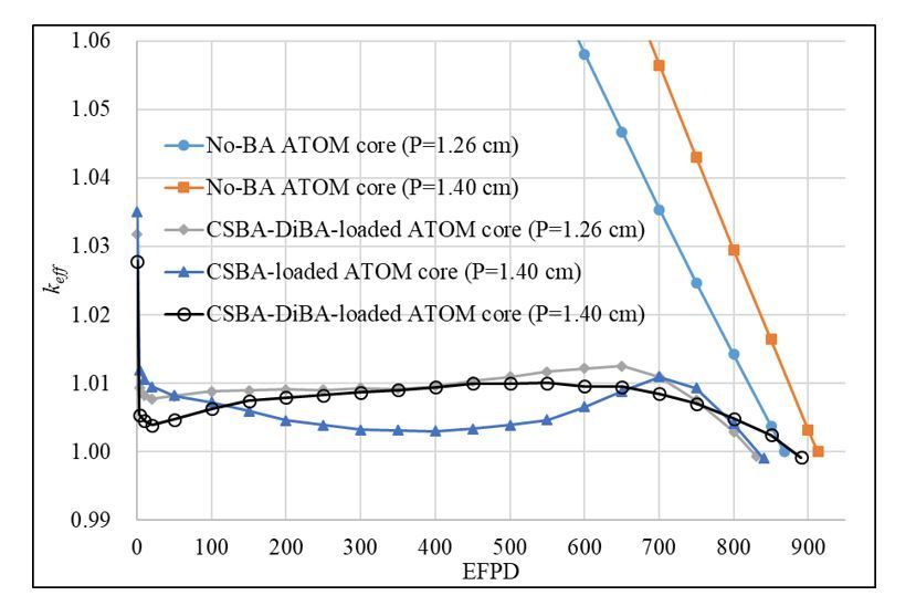
among several options. Since this work is largely concerned with the neutronic attributes of the TOP
concept, it is assumed that the average coolant speed remains unchanged and the coolant inlet
temperature is appropriately increased for a given coolant temperature rise. In this case, the FA thermal-
hydraulics will be quite similar to the conventional one, while the balance of the plant design should be
accordingly modified. Meanwhile, the coolant speed can be reduced significantly in the TOP design if the
same coolant temperature rise is adopted, and the core pressure drop should decrease a lot. However, in
this approach, the thermal-hydraulics will be quite different due to a slower coolant flow, e.g., the critical
heat flux can be lowered if other design measures are not introduced. Therefore, the thermal-hydraulic
design for the TOP lattice needs to be optimized for the given plant system.

2.2. Innovative Burnable Absorbers for the TOP ATOM Core
To obtain a very small excess reactivity in the SBF ATOM core without compromising the core
performances, a new innovative 3-D BA design, centrally-shielded burnable absorber (CSBA), is utilized
[5]. In the CSBA design, gadolinia (Gd2O3) is loaded into the central region of the fuel pellet in the
spherical form, which provides the strongest self-shielding effect of the BA, resulting in slow gadolinium
depletion. .

A recent 3-D multi-physics study [16] demonstrated that the effective stress at the interface between
CSBA balls and fuel is very acceptable, while the maximum temperature of the CSBA-loaded fuel pellet is
comparable to that of the conventional one. In addition, the effect of asymmetric power distribution due
to neighboring effect on the fuel temperature is relatively small, about 15K in terms of peak temperature
and subsequent thermal expansion and stress are hardly changed. Moreover, the material and
experimental studies for the CSBA-loaded fuel are currently under-investigation and several preliminary
outcomes are available at references [17] [18].

Gadolinia is an effective and well-proven BA material in the nuclear technology. However, it is
disadvantageous in that the residual gadolinium isotopes, e. g., Gd-158 and Gd-160, result in noticeable
reactivity penalty. In addition, a simple 1-ball CSBA design is more favorable than 2-ball and 3-ball
designs in terms of fabrication and quality control. Therefore, for a more flexible reactivity control, B4C is
additionally used as the second BA material to reduce the residual gadolinium for enhanced neutron
economy. In this work, B4C is used in the form of disk-type burnable absorber (DiBA), which was recently
proposed [19]. A combination of the two BA designs is shown in Fig. 6. The B4C disk is cladded with Zr-4
with axial cladding thickness of 0.04 mm, while the outer diameter of radial cladding is the same as pellet
diameter. The number of DiBA is identical to the number of fuel pellets per fuel rod, so-called 1P1D (1
pellet 1 DiBA) option.

Advantage of DiBA is that the self-shielding effect can be flexibly adjusted by controlling both the height-
to-diameter (H-to-D) ratio and the volume of the BA disk as shown in Fig. 7, in which neutronic
calculations of 17x17 lattice are performed with the Serpent 2 code. The number of active and inactive

                                                   Page 6/29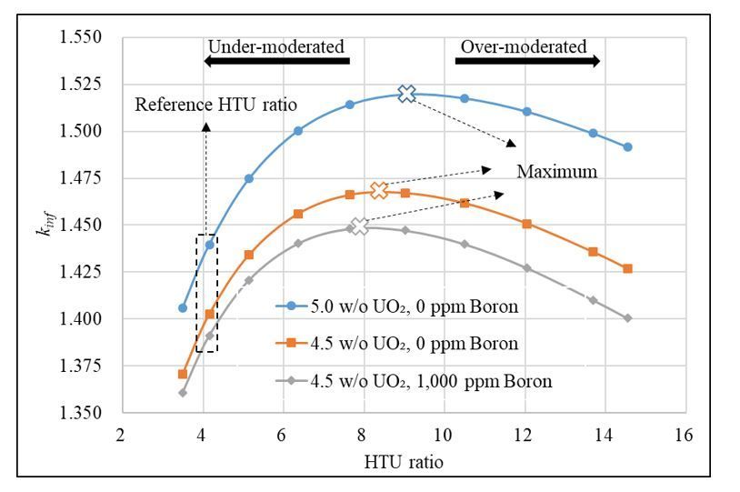
cycles are 200 and 100, respectively, with 100,000 histories. One should note that the amount of B4C
should be limited so that the internal rod pressure due to fission gas and helium gas from B-10 depletion
should not exceed the upper limit. In this study, the B4C volume is adjusted so that B-10 loading should be
0.09 mg B-10 per mm pellet, which is typical of the conventional IFBA design [20]. A 90% enriched B-10 is
utilized to minimize the DiBA volume.
Figure 7b compares the kinf value for B4C DiBA designs and ZrB2 112-IFBA design [9]. The kinf values of
the DiBA case with 0.016 cm3 B4C (BA volume =0.8 V) and the IFBA case at the fresh condition are
adjusted to be the same for a consistent neutronic comparison. It can be seen clearly that the kinf of IFBA
design increases significantly after Xenon equilibrium. It is because boron in the IFBA design quickly
burns out as the ZrB2 coating layer exposes largely to the neutron flux. The kinf of the IFBA design
decreases linearly and follows the no-BA case once boron depletes completely at 20 GWd/tU. On the
other hand, boron in the DiBA case depletes rather slow as the kinf stays around 1.05 until 30 GWd/tU. It is
due to the H-to-D ratio close to 1.0, which minimizes the exposure of the BA to neutron flux. However, the
reactivity penalty of the DiBA design is higher than that of the IFBA as a large amount of BA is necessary
to hold down the excess reactivity throughout the cycle.
3. The Sbf Two-batch Atom Core
3.1. The ATOM Core Design
Major design parameters and cross-sectional views of the ATOM core are presented in Table V and Fig. 8,
respectively. Thermal power of the core is set to 450 MWth and the active core consists of 69 TOP-based
FAs with 2 m active height. The active core is surrounded by a stainless steel reflector and the axial
reflector composition is adopted from the typical PWR design. The enrichment of UO2 fuel is 4.95 w/o
with 95.5% theoretical density. At the top and bottom of the active core, 5 cm blanket with 2.0 w/o
enrichment and 5 cm BA cutback with enrichment of 4.95 w/o are placed, as shown in Fig. 8. To achieve
a reactivity swing smaller than 1,000 pcm, both 1-ball CSBA design and 1P1D DiBA designs are adopted
[5], as shown in Fig. 6. Note that each FA has a single CSBA and DiBA design for simplicity. An accident-
tolerant-fuel (ATF) cladding, Cr15Al-coated Zir-4, is also utilized for improved safety of the reactor [11], in
which the Cr15Al coating thickness is 30 micron.
A two-batch fuel management (FM) is adopted to maximize both cycle length and fuel burnup in this
work and the fuel loading pattern is shown in Fig. 9. For enhanced neutron economy, the core utilizes an
in-then-out fuel shuffling scheme as shown in Fig. 9 and Table VI. Most of fresh FAs are loaded in the
inner regions while burned FAs are located mostly in the peripheral regions to minimize the neutron
leakage. Several burned FAs are placed in the inner core for a flat radial power profile. The central FA is
separately treated with an enrichment of 3.0 w/o and the number of standard feed FAs is 34 with 4.95
w/o UO2. Due to the number of the fresh FAs, the core is rotationally symmetric. Except for the center FA,
the fresh FAs are radially divided into three zones: Zone I, zone II, and zone III. There are 16 fresh FAs in
Page 7/29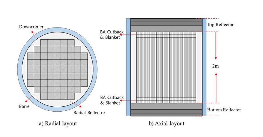
the inner region, zone I, where the power is the highest in general. These FAs are then shuffled into
outermost positions introducing the lowest leakage as they are highly burned after their first cycle. On the
other hand, 4 fresh FAs in the outermost zone, zone III, are shuffled into the center positions surrounding
the center FA to reduce the power peaking here. Meanwhile, the other four FAs in zone III are reloaded in
the outer positions, F1 and E5. Most of fresh FAs in zone II follow in-then-out shuffling scheme, in which
they are shuffled to the neighboring outer positions, for example from F4 to F5, whereas fresh FAs in K1
position are reloaded in to E4.

Figure 9 also shows the CR pattern of the core and the CR design parameters are presented in Table VII. It
is noteworthy that a pseudo checker-bard pattern is adopted in the current ATOM core. The CR pattern
comprises 32 shutdown CRs, 8 regulating CRs, and 5 mechanical shim (MS) CRs, respectively. In the TOP
FA design, the CR is designed to be a little bigger than that in the standard one [9] for improved CR worth.
A B4C with 90 w/o B-10 is used as the material for the shutdown rod, while the regulating rod is based on
natural B4C. The MS is supposed to be rather weak and its absorber material is an Hf-doped SS-304. The
use of SS-304-based MS is to minimize power distortion during criticality attainment with the MS.

Table VIII shows the BA loading pattern for the ATOM core. To flat radial power distribution, the biggest
CSBA ball is loaded into the inner zone, zone I, while smaller balls are placed in the outer regions. The
CSBA design in the center FA is the same with that in zone III. On the other hand, only single design of the
B4C DiBA is used for the simplicity of the core design. Thickness of the B4C disk is 40 micron, while the
B4C disk radius is 0.22 cm. The total BA height, including B4C and Zr-4 clad, is 120 micron, resulting in an
axial active core height of about 202 cm, about 2% higher than its original value [5].

3.2. Numerical Results and Discussion
To investigate the neutronic performance of the ATOM core, the Monte Carlo Serpent 2 code has been
used with the library ENDF/B-VII.1 [7]. The number of active and inactive cycles are 300 and 100,
respectively, with 300,000 histories per cycle. The associated uncertainty of the multiplication factor (keff)
is about 10 pcm. In the Serpent calculation, the effective temperature of the fuel is fixed at 840K [21] and
a linearly varying axial coolant temperature is considered with an average temperature of 575K.
Temperatures at CZP and HZP are 294K and 558K, respectively.

The neutronic performances of several equilibrium cycles are shown in Fig. 10 and Table IX. It can be
observed that the excess reactivity can be very successfully minimized by using the CSBA and DiBA
technologies, and the cycle length of the TOP cores is significantly enhanced compared to that of the
standard FA design with the pin pitch of 1.26 cm. One can see that the cycle length is extended by ~73
effective full power days (EFPDs) in the CSBA-DiBA-loaded core. On the other hand, it is also noteworthy
that the CSBA-DiBA core provides about 60 EFPDs longer cycle length than the CSBA-only one, which is
clearly due to quite smaller reactivity penalty due to residual gadolinium in the CSBA and DiBA hybrid
case. As a result, Table IX confirms that the fuel discharge burnup is similarly increased with the TOP-

                                                   Page 8/29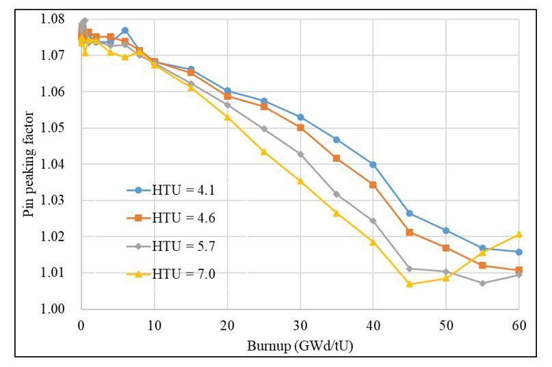
based. In all candidate equilibrium cores, the reactivity swing is only around 1,000 pcm and this is very
favorable for the SBF operation since the criticality can be easily controlled by using weak CRs such as
MS in Table VI without causing local power peaking issue.

For the CSBA-DiBA TOP-based core, assembly-wise radial and core-wise axial power profiles are depicted
in Figs. 11 and 12, respectively. It is observed that the radial peaking factor is rather small, ~1.5 at the
EOC condition, even though the fuel shuffling is based on a low leakage scheme. The axial power profile
is clearly bottom-skewed at the BOC due to the SBF condition and it becomes slightly top-skewed at EOC,
and the axial peaking factor is less than 1.3 at any condition. The associated uncertainties for radial and
axial powers are 0.5% and 0.2%, respectively. Appropriate axial zoning of the BAs can be easily adopted
to alleviate the skewed power distributions.

Table X shows temperature coefficients of the CSBA-DiBA TOP-based ATOM core for various conditions.
In the temperature coefficient evaluation, the maximum associated uncertainty of FTC and MTC is 0.08
pcm/K and 0.30 pcm/K, respectively. Both MTC and fuel temperature coefficient (FTC) are clearly
negative at any conditions, assuring the inherent safety of the ATOM core. One should note that the HFP
MTC is always strongly negative and its variation is only about -3 pcm/K between BOC and EOC* due to
the TOP design, while it is about -14 pcm/K with the standard pitch design [5]. It is important to note that
there is no concern about ‘too much negative’ MTC in the ATOM core due to the TOP concept, which will
improve its operational safety and flexibility. Such appropriately negative MTC values are favorable for
the autonomous operation of the reactor as it minimizes the coolant temperature variation [15].

The (N-1) shutdown margin was evaluated assuming a CR is stuck out at the CZP condition and Table XI
shows the result. The statistical uncertainty of the rod worth in Table XI is less than 10 pcm. The
shutdown evaluation is evaluated at both CZP-BOC and CZP-EOC* conditions without any Xe in the core.
Note that excess reactivity is noticeable at EOC* while core characteristics are very similar to those of
EOC. It is very clear that the proposed pseudo CR pattern provides enough N-1 shutdown margin to assure
sub-criticality at the CZP condition.

In the ATOM core, both MS and RR are to be used for reactivity control during normal operations and the
HFP excess reactivity is supposed to be compensated by the MS only at the Xe-equilibrium condition.
Table XII lists the reactivity worth of the MS and regulating CR at both HZP and HFP conditions without
Xe. The maximum associated uncertainties in the rod worth are about 7.0 pcm. The MS rod worth is
about 1,000 pcm, which is sufficient to compensate for the burnup reactivity swing during the cycle. It is
also noted that all excess reactivity at HZP without Xe can be controlled by using both MS and regulating
rods.

It is recalled that MS rods should be rather fully inserted during the normal full power operation and they
are to be gradually withdrawn near EOC for criticality control. The MS withdrawal near EOC should lead to
a higher local power nearby guide tubes. To evaluate impact of the MS movement on the local power in a
conservative way, a single MS-rodded FA was depleted to a high burnup of 30 GWD/tU and the MS rods
were pulled out at 30 GWD/tU. Figure 13 shows the power distributions due to the MS maneuvering. In
                                                  Page 9/29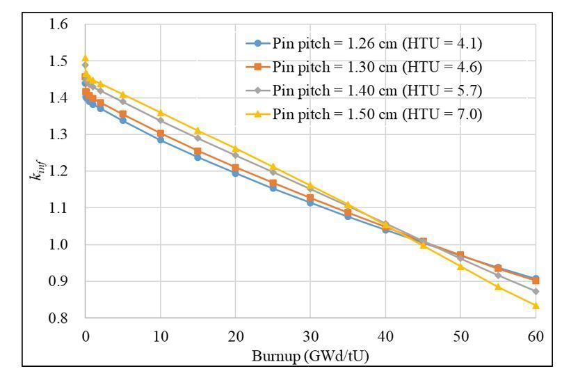
Fig. 13, uncertainty of the pin powers is about 0.3%. One can see that the pin power distribution is rather
flat with a peaking factor of 1.13 at the FA corner even when all MS rods are fully inserted. It is also noted
that the peak power is only about 1.07 near a guide tube when all MS rods are suddenly pulled out at 30
GWD/tU. Therefore, it is clear that the use of MSs is fully acceptable for the excess reactivity control in
the SBF ATOM core.

4. Conclusions And Future Works
The current work demonstrates that use of the TOP lattice clearly improves both cycle length and
discharge burnup of the SBF SMR. Moreover, the TOP FA design also results in the more desirable MTC
and FTC for inherent safety, power maneuvering, and autonomous operation of the SBF core, while the
cold shutdown is guaranteed with a pseudo checker-board control pattern. On the other hand, the
innovative CSBA and/or DiBA technologies enable a high-performance SBF design of the ATOM core in
which the burnup reactivity swing is less than 1,000 pcm. As a result, the criticality control of the SBF core
is achievable with a weak MS bank only and the consequent local power perturbation is quite marginal.
Furthermore, it is shown that the use of B4C DiBA in the CSBA-DiBA hybrid case can significantly reduce
the reactivity penalty due to residual gadolinium isotopes in the CSBA, enabling a quite longer cycle
length. Overall, a high-performance SBF ATOM core has been successfully developed by utilizing the TOP
lattice and the CSBA-DiBA hybrid designs. It is expected that the newly proposed TOP-based SBF core
concept would be a new design paradigm for future high-performance PWRs.

The axial power distribution of the SBF ATOM core is rather bottom-skewed at the BOC condition due to
the strongly negative MTC. An axial BA zoning will be implemented to achieve more favorable axial
power shapes. In addition, further optimization on the CR pattern will be done to introduce a fully checker-
board CR arrangement.

Declarations
Acknowledgement
This work was supported by the National Research Foundation of Korea (NRF) Grant funded by the
Korean Government (MSIP) (NRF-2016R1A5A1013919).

Nomenclature
ATOM : Autonomous Transportable On-demand Reactor Module

BA : Burnable Absorber

BOC : Beginning of Cycle

                                                  Page 10/29
CASMRR : Center for Autonomous Small Modular Reactor Research
CSBA : Centrally-Shielded Burnable Absorber
CR : Control Rod
CZP : Cold Zero Power
DiBA : Disk-type Burnable Absorber
EOC : End of Cycle
FTC : Fuel Temperature Coefficient
HFP : Hot Full Power
H-to-D : Height-to-Diameter
HTU : Hydrogen-to-Uranium
HZP : Hot Zero Power
KAIST : Korea Advanced Institute of Science and Technology
MOC : Middle of Cycle
MS : Mechanical Shim Rod
MTC : Moderator Temperature Coefficient
PWR : Pressurized Water Reactor
SB : Soluble Boron
SBF : Soluble-Boron-Free
SSE : Self-Shielding Effect
SMR : Small Modular Reactor
TH : Thermal Hydraulics
References
Page 11/29[1] G. Alex, S. Meir and R. Alvin, "Substitution of the Soluble Boron Reactivity Control System of a
Pressurized Water Reactor by Gadolinium Burnable Poisons," Nuclear Technology, vol. 75, pp.
127-133, 1986.
[2] M. S. Yahya and Y. Kim, "An innovative core design for a soluble‐boron‐free small pressurized
water reactor," International Journal of Energy Research, pp. 1-9, 2017.
[3] J. Kim, H. Cho, M. Do and K. Seong, "Use of Solid Pyrex Rod for Conceptual Soluble Boron Free
SMR," in Transaction of the American Nuclear Society, Las Vegas, 2016.
[4] "GIF and Generation-IV," in ANS Winter Meeting, San Diego, USA, 2012.
[5] X. H. Nguyen, C. H. Kim and Y. Kim, "An advanced core design for a soluble-boron-free small
modular reactor ATOM with centrally-shielded burnable absorber," Nuclear Engineering and
Technology, vol. 51, pp. 369-376, 2019.
[6] P. Thomet, "Feasibility Studies of a Soluble Boron-Free 900-MW(electric) PWR, Core Physics–I:
Motivations, Assembly Design, and Core Control," Nuclear Technology, pp. 259-266, 2017.
[7] J. Leppänen, M. Pusa, T. Viitanen, V. Valtavirta and T. Kaltiaisenaho, "The Serpent Monte Carlo
code: status, development and applications in 2013," Annals of Nuclear Engergy, vol. 82, pp.
142-150, 2015.
[8] B. Cho, S. Yuk, N. Z. Cho and Y. Kim, "User's manual for the rectangular three‐dimensional
diffusion nodal code COREDAX‐2 version 1.8," KAIST, Daejeon, Korea, 2016.
[9] K. S. Kim, T. J. S. G. Hong and J. W. Song, "Benchmark Matrix for Verification and Validation of
the KARMA code," KAERI, Daejeon, 2010.
[10] KEPCO and KHNP, "APR1400 Design control document tier 2: chapter 4," U. S. NRC, Maryland,
2014.
[11] X. H. Nguyen, S. D. Jang and Y. Kim, "Impacts of an ATF Cladding on Neutronic Performances
of the ATOM SMR Core," in The 6th International Conference on Nuclear and Renewable Energy
Resources (NURER2018), Jeju, Korea, 2018.
[12] C. K. Jo, N. Z. Cho and Y. Kim, "Graphite-filled mixed-oxide fuel design for fully loaded PWR
cores," Annals of Nuclear Energy, vol. 27, pp. 819-829, 2008.
[13] P. Barbrault, "A plutonium-fueled high-moderated pressurized water reactor for the next century,"
Nuclear Sience and Engineering, vol. 122, p. 240, 1996.
[14] Y. B. Kim, "Feasibility study of a moderation-enhanced reactor core loaded 100% with MOX
fuel," PhD Thesis, KAIST, Daejeon, 1996.
[15] A. A. E. Abdelhameed, J. Lee and Y. Kim, "Physics conditions of passive autonomous frequency
control operation in conventional large-size PWRs," Progress in Nuclear Energy, vol. 118, 2020.
[16] H. Kim and Y. Kim, "Unstructured Mesh–Based Neutronics and Thermomechanics Coupled
Steady-State Analysis on Advanced Three-Dimensional Fuel Elements with Monte Carlo Code
iMC," Nuclear Sience and Engineering, pp. 1-14, 2021.
[17] Q. M. Mistarihi, W. Park, K. Nam, M. S. Yahya, Y. Kim and H. J. Ryu, "Fabrication of oxide pellets
containing lumped Gd2O3 using Y2O3‐stabilized ZrO2 for burnable absorber fuel applications,"
International Journal of Energy Research, vol. 42, pp. 2141-2151, 2018.
[18] Q. Mistarihi, F. B. Sweidan and H. J. Ryu, "Thermo-physical properties of bulk Gd2O3 for fuel
performance analysis of a lumped burnable absorber fuel design," in Transaction of the Korean
Page 12/29Nuclear Society, Gyeongju, Korea, Oct. 25-27, 2017.
[19] X. H. Nguyen, S. Jang and Y. Kim, "A Spectral Optimization Study of Fuel Assembly for Soluble-
Boron-Free SMR," in Korea Nuclear Society, ICC, Jeju, 2020.
[20] O. R. N. Laboratory, "Study of the Effect of Integral Burnable Absorbers for PWR Burnup Credit,"
U.S. Nuclear Regulatory Commission, Washington, 2002.
[21] A. Rahman, X. H. Nguyen and Y. Kim, "A Study on Effective Temperature of CSBA-loaded UO2
Fuel Pellet," in Transactions of the Korean Nuclear Society Autumn Meeting, Oct. 25-27,
Gyeongju, Korea, 2017.
[22] M. S. Yahya and Y. Kim, A New Approach for a High-Performance Soluble-Boron-Free PWR core,
PhD Thesis, Daejeon: KAIST, 2016.
[23] "COMSOL Multiphyiscs (R) v. 5.4. www.comsol.com.," COMSOL AB, Stockholm, Sweden, 2018.
[24] J. K. Fink, "Thermophysical properties of uranium dioxide," Journal of Nuclear Material, vol.
279, pp. 1-18, 2000.
[25] F. B. Sweidan and H. J. Ryu, "Composite Material Properties Simulation for the Fuel
Performance evaluation of Gadolinia-cored UO2 Fuel," in Water Reactor Fuel Performance
Meeting, Jeju, Korea, 2017.
[26] IAEA-TECDOC-1496, "Thermophysical properties database of materials for light water reactors
and heavy water reactors," IAEA, final report, 1999-2005.
Tables
Table I: Reference 17×17 FA design specification
Parameter Value
Fuel lattice 17x17
No. of fuel rods / guide tubes 264 / 25
Fuel material / pellet radius UO2 / 0.40958 cm
Cladding inner / outer radii 0.41873/ 0.47600 cm
Reference pin pitch 1.2623 cm
Reference FA pitch 21.6038 cm
Reference HTU ratio 4.1
Coolant / fuel temperatures 575 K / 900 K
Page 13/29Table II: Cycle length and discharge burnup for various HTU ratios
HTU ratio Pin pitch (cm) Discharge burnup (GWd/tU) Cycle length (days) FA pitch
(cm)
4.1 1.26 46.4 913 21.60382
4.6 1.30 47.5 936 22.24472
5.7 1.40 47.7 940 23.94472
7.0 1.50 46.3 911 25.64472
Table III: Temperature coefficients (pcm/K) for various HTUs at HFP
HTU MTC @ 0 GWd/tU MTC @ 60 GWd/tU
Wo/ BA W/ BA Wo/ BA W/ BA
4.1 -23.5 -33.4 -58.33 -61.7
4.6 -22.2 -31.0 -50.16 -54.9
5.7 -15.4 -23.9 -33.47 -36.9
7.0 -8.60 -16.9 -16.8 -18.6
HTU FTC @ 0 GWd/tU FTC @ 60 GWd/tU
Wo/ BA W/ BA Wo/ BA W/ BA
4.1 -1.91 -2.97 -3.75 -3.87
4.6 -1.74 -2.79 -3.50 -3.64
5.7 -1.52 -2.38 -2.95 -3.12
7.0 -1.30 -2.04 -2.52 -2.66
Table IV: Temperature defect with respect to HTU ratio and burnup
Page 14/29Case @ 0 GWd/tU @ 60 GWd/tU
HTU = 4.1 4,941 pcm 7,943 pcm
HTU = 4.6 4,490 pcm 7,045 pcm
HTU = 5.7 3,359 pcm 4,484 pcm
HTU = 7.0 2,302 pcm 1,833 pcm
Table V: Major design specifications of the TOP-based ATOM core
Parameter Value
Thermal power 450 MWth
FA type, number of FA 17×17, 69
Fuel material, enrichment UO2, 4.95 w/o
Pellet radius 0.40958 cm
Pin pitch (cm) 1.40 cm
Radial reflectors SS-304
BA designs 1-ball CSBA, 1P1D DiBA
Gd2O3 density in CSBA 99% TD *
B-10 enrichment in DiBA 90 w/o
No. of feed/burned FAs 35/34
*TD: theoretical density
Table VI: Fuel shuffling scheme of the two-batch TOP ATOM core
Page 15/29Zone I Zone II Zone III
Fresh Burned Fresh Burned Fresh Burned
C2 A3 B2 A2 B3 H1
D2 B4 D4 D5 C4 E2
D3 C5 F4 F5 G4 E5
E3 C3 H2 K2 H3 F1
F2 H4 K1 E4
F3 G5
G1 G3
G2 K3
Table VII: CR design for the two-batch TOP ATOM core
Parameters Value
CR radius (cm) 0.51674
CR gap radius (cm) 0.52055
CR clad radius (cm) 0.56754
Inner tube radius (cm) 0.63979
Outer tube radius (cm) 0.70000
Shutdown rod material 90 w/o B-10 B4C
Regulating rod material Natural B4C
MS material SS-304 with 13.5 w/o Hf
Table VIII: The BA design for the TOP ATOM core
Page 16/29Zone CSBA radius DiBA radius DiBA height Fuel enrichment
I 1.45 mm 2.2 mm 40 micron 4.95 w/o
II 1.25 mm 4.95 w/o
III 1.18 mm 4.95 w/o
Center FA 1.18 mm 3.00 w/o
Table IX: Neutronic performance of the ATOM cores
Case Reactivity swing Cycle length Discharge burnup
(pcm) (EFPD) (GWd/tU)
No-BA (Standard) - 868 44.1
No-BA (TOP) - 913 46.5
CSBA-DiBA (Standard) 1,239 817 42.8*
CSBA-only (TOP) 1,040 830 44.3*
CSBA-DiBA (TOP) 988 890 45.6*
*without central FA
Table X: Temperature coefficients of the TOP ATOM core
Condition MTC (pcm/K) FTC (pcm/K)
HFP-BOC -38.60 -2.20
HZP-BOC -33.49 -2.54
HFP-EOC* -41.03 -2.34
HZP-EOC* -35.05 -2.64
EOC*: @ 700 EFPD near EOC
Table XI: Shutdown margin of the TOP-based ATOM core
Page 17/29Scenario BOC, No Xe EOC*, No Xe
(CZP) keff Rod worth (pcm) keff Rod worth (pcm)
ARO (all-rod-out) 1.08376 - 1.09203 -
ARI (all-rod-in) 0.95109 12,871 0.92609 16,408
N-1 (E1)** 0.96458 11,401 0.94449 14,304
N-1 (F2)** 0.97922 9,850 0.97717 10,763
N-1 (E3)** 0.97255 10,551 0.97905 10,567
N-1 (F4)** 0.96797 11,038 0.96889 11,638
N-1 (G3)** 0.95110 12,870 0.92872 16,103
EOC*: @ 700 EFPD near EOC, **Stuck rod position
Table XII: Mechanical shim and regulating rod worth for the ATOM core
No Xenon BOC EOC*
keff Rod worth keff Rod worth
(pcm) (pcm)
ARO (HZP) 1.03640 - 1.04324 -
All-MS- and RR**-In (HZP) 0.98839 4,686 0.99849 4,597
ARO (HFP) 1.02787 - 1.03380 -
All-MS-In (HFP) 1.01757 985 1.02289 1,031
EOC*: @ 700 EFPD near EOC, **Regulating Rod
Figures
Page 18/29Figure 1
17×17 commercial PWR lattice
Page 19/29Figure 2
The infinite multiplication factor with respect to HTU value
Page 20/29Figure 3
The burnup-dependent kinf behavior with respect to various HTU values
Page 21/29Figure 4
Neutron spectrum with respect to HTU ratio and burnup
Page 22/29Figure 5
Burnup-dependent PPK with respect to HTU value
Figure 6
Page 23/29DiBA and CSBA-loaded fuel pellet
Figure 7
Infinite multiplication factor of the DiBA-loaded FA with respect to BA volume and H-to-D ratio
Page 24/29Figure 8
The radial and axial ATOM core layouts
Figure 9
Radial zone-wise fuel loading and CR pattern
Page 25/29Figure 10
The excess reactivity of several equilibrium cores
Page 26/29Figure 11
Radial assembly-wise power distribution of the TOP ATOM core
Page 27/29Figure 12
Core-wise axial power distribution of the TOP ATOM core
Page 28/29Figure 13
Power distribution of the one-eighth BA-loaded FA with and without MS
Supplementary Files
This is a list of supplementary files associated with this preprint. Click to download.
Supplementaryinformation.docx
Page 29/29You can also read