9 December, 2018 - Infineon Technologies
←
→
Page content transcription
If your browser does not render page correctly, please read the page content below
1 9 December, 2018

Updates to last version from 31.07.2018
Following slides were updated:
slide 2, 4, 30 - 31, 33, 34 - 37, 39 - 40, 43
2 9 December, 2018
Agenda
Motivation: Environmental and health endangerment by lead
Situation: Lead & the use in Electronics
Status on legislation
DA5 Structure and Project:
Cooperations and partners
Requirements, Applications and Approaches for possible solutions
Results
Timeline and Conclusion
3 9 December, 2018
Sustainability Efforts I

Bosch:
For the Bosch Group, sustainability means securing the company’s long-term success while at the same time protecting the
natural resources on which present and future generations depend. The strategic imperative “Invented for life” thus
expresses the aim to make mobility even safer, cleaner, and more economical, and to develop eco-friendly products in
general. Ecology is thus a driver of innovation: in 2018, more than half of research and development expenditure at Bosch
went into products that help improve energy efficiency, environmental protection, and resource conservation.

Infineon:
We understand sustainability as the symbiosis between economy, ecology and social engagement.
At Infineon, we responsibly manage the handling of hazardous materials to safeguard human
health and environmental protection. As part of Infineon Group Policy for Environmental
Protection, Energy Management, Safety and Health, we are moving towards supply
chain responsibility, focusing on the purchase of new environmentally friendly materials
in the manufacture of its products. Products manufactured by Infineon in the
fields of automotive electronics, industrial drives, servers, lighting, photovoltaics,
wind energy, mobile phone chargers and induction cookers alone,
enable CO2 emission savings amounting to approximately 56 million tons
of CO2 equivalents during their use-phase. For the ninth time in a row,
Infineon has been listed in the “Dow Jones Sustainability™ Europe Index” and for
the forth time in the “Dow Jones Sustainability™ World Index”.

  4                                                                                                   9 December, 2018
Sustainability Efforts II
NXP:
At NXP we make every effort to ensure that our products and working practices are responsible and sustainable. Our
ambition is to go beyond compliance and to establish a global benchmark for sustainability in our industry. We foster ethical
principles and respect for the environment, people, and in the communities in which we work. Sustainability is a part of the
way we conduct our business, the way we manage our company, and the way we interact with society at large.

Nexperia:
We are committed to provide a safe working environment, promote good health, minimize the environmental impact of our
activities and protect the environment with our way of working and the products we develop. We foster innovations and
creative solutions that add value for our customers, communities and our planet. We define Sustainability as part of our
"Efficiency wins" strategy through the inclusion of environmental, health & safety, social and governance issues in our
business strategy. Sustainability is part of everyday work of all employees worldwide, from the
Executive Management Team to each single employee, from product development until disposal.

STM:
As part of ST Sustainable Technology Program, embedded in its 5th EHS Decalogue
2014-2020, ST is committed to design products continuously decreasing energy
consumption and enabling more energy efficient applications that create value for
all stakeholders, with a focus on healthcare, safety/security, society and
environment, strive towards a «product greening strategy» through Ecopack®
program deployment and 100% recyclable packing materials free of hazardous
substances, as well as continuously applying the eco-design process for new
products.

  5                                                                                                      9 December, 2018
Examples for Environmental Protection

                                                                  CRI
                        Powertrain            Innovative electro-tools   Photovoltaic
                                               with Li-Ion technology

    Saving energy in
     basestations

                                                                         Energy efficient
                       Wind energy (gears)        Solar thermal            appliances
                          ESP

    Power plant                                                               More efficient SSL
                           Household/Office            Smart grid                  lighting

6                                                                                 9 December, 2018
Lead: Environmental and Health Endangerment
Environmental dangers
Health dangers:
Poisonous substance
Neurotoxin
Accumulates in soft tissues & bones
Damage to nervous system
Causes brain disorder
Causes blood disorder in mammals
7 9 December, 2018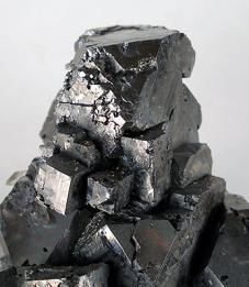
Agenda
Motivation: Environmental and health endangerment of lead
Situation: Lead & the use in Electronics
Status on legislation
DA5 Structure and Project:
Cooperations and partners
Requirements, Applications and Approaches for possible solutions
Results
Timeline and Conclusion
8 9 December, 2018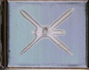
Use of Lead in Electronics
                                           Exemption                                        Expiry / Review
                                                                                                  Date

    Lead in soldering on PCB, the components and their finishes                                   E/2015

    Lead in solder for other application, not on PCB or glass                                     E2010

    Lead in finishes of Al-Capacitors                                                             E/2012
                                                                     example IC packages

    Lead in soldering on glass for mass-flow sensors            2                                 E/2014

    Lead in high temperature melting solders                                                  Review 2019

    Lead in compliant pin connector systems                                                   Review 2019

                                                                                                                           FlipChip
                                                                                                                           Lotbump
    Lead in solder between die and carrier in flip chip packages                              Review 2019                  Interposer
                                                                                                                           Lotball
                                                                                                                           Leiterplatte

    Lead in solder of IC assemblies with >1cm² die and >1A/mm²                                Review 2014

                                                                                               not recom-
    Carry over parts without expiry date
                                                                                                mended.

9                                                                   Expiry Dates referring to vehicle type approval   9 December, 2018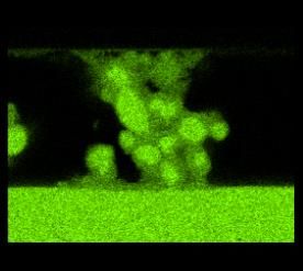
Use of Lead in Electronics
Use of Lead containing Solders in PCB
PbSn63 or PbSn62Ag2
are & have been used for soldering components onto a
printed circuit board (PCB)
Leadfree alternative solders known & implemented
E.g. SnAg3.8Cu0.7 (SAC)
Use of high Lead containing Solders as chipsolders in packages
PbSn5 or PbSn2Ag2.5
are used for die attach applications
No re-melting during PCB reflow process
Excellent wettability
Reliable due to ductility
Commercially competitive
Today no alternative drop-in solution available
10 9 December, 2018Materials for Die Attach: Solder Alloys
Melting
Melting temperature
temperature of solder alloys
400
400
Tem perature load
350
350 ( d ur ing sub seq uent assemb ly p r o cesses
& p cb - so ld er ing )
in °C
°C
300
300
Temperature in
Temperature
250
250
200
200
150
150
100
100
n
Ag
Ag
Ag
b
b
b
n
Sn
n
gg
Ag
g
n
n
2S
0S
9I
5S
8S
Pb b5S
0S
A
A
3A
9Z
48
b2
.5
.5
.5
.5
IInn3
b1
i4
g1
u2
Sn
Sn
Sn
3
n2
n2
n1
In
P
B
P
P
Sn
A
A
36
5S
2S
1S
25
Sn
Pb
Pb
Sn
Alloy
Tmelt/°C Tmin/°C Tmax/°C
11 9 December, 2018Materials for Die Attach: Solder Alloys
Melting
Melting temperature
temperature of
of solder
solder alloys
400
400
Tem perature load
350
350 ( d ur ing sub seq uent assemb ly p r o cesses
& p cb - so ld er ing )
Temperature in °C
300
300
250
250
200
200
150
150
100
100
nn
bb
2S Ag
Ag
Ag
b
b
n
SSnn
In
gg
g
g
Zn
5S Sn
2SS
A
00SS
55SS
8S
5S
A
3A A
19
ii442
488
n9
0
b2
.5
.5
.5
.5
IInn3
IInn4
g11
u2
SSnn
Sn
Pb
Pb
n2
3
n2
n1
Ag
S
BB
P
Sn
55A
A
36
1S
n2
Sn
Pb
Pb
Pb
Sn
Alloy
Tmelt/°C
Tmelt/°C Tmin/°C Tmax/°C
12 9 December, 2018Materials for Die Attach: Solder Alloys
Melting temperature
Melting temperature of
of solder
solder alloys
400
400
Tem perature load & lead-free
Tem perature load
350
350 ( d ur ing sub seq uent assemb ly p r o cesses
& p cb - so ld er ing )
°C
in °C
300
300
Temperature in
Temperature
250
250
200
200
150
150
100
100
nn
2S Ag
Ag
Ag
b
b
b
n
SSnn
Sb
In
gg
g
g
Zn
n
2SS
A
55SS
8S
Pb b5S
A
A
00S
3A
Pb 20S
19
ii442
488
n9
b2
.5
.5
.5
.5
IInn3
IInn4
g11
SSnn
Sn
Pb
n2
3
n2
n1
S
P
Ag
u
BB
P
Sn
55A
A
36
5S
1S
n22
Sn
Pb
SSn
Alloy
Brittleness of remaining alloys limits
Tmelt/°C
Tmelt/°C Tmin/°Creliability
Tmax/°Cto only smallest
die sizes with severe constraints on chip thickness,
package geometry and surface materials.
13 9 December, 2018Agenda
Motivation: Environmental and health endangerment of lead
Situation: Lead & the use in Electronics
Status on legislation
DA5 Structure and Project:
Cooperations and partners
Requirements, Applications and Approaches for possible solutions
Results
Timeline and Conclusion
14 9 December, 2018Legislation
European End-of-Life Vehicle (ELV) Directive (2000/53/EG)
mandates conversion to environmentally friendly materials
Annex II (2010/115/EU, exemptions 8e-j/10d) ELV 7th Adaptation
Exemption may be cancelled if an alternative is available and proven
For 8e (lead in HMT solder) new exemption extension went into force May 2016 and is valid until 7/2019
The Stakeholder Consultation of ELV Annex II 9 th revision started end of May‘18 and EU COMM decision
expected in 2019
European RoHS Directive (2011/65/EU)
restricts the use of hazardous substances in electrical and electronic equipment
RoHS exemptions allow temporary use of restricted substances.
See Annex III in 2011/65/EU (RoHS-2) for exemptions.
RoHSII recast went into force 1st of July 2011
Industry associations consortium(34 associations) sent an extension dossier regarding exemption 7a to the
EU COMM on 16th of January ’15
The revision process is finished; regarding 7a the EU COMM and the EU Parliament decided to extend the
exemption to July 2021 using the same wording
Exemption 7a (lead in high temperature melting solders) valid until mid 2021 will automatically extend until
EU COMM decides on running exemption extension process starting Jan. 2020 latest
15 9 December, 2018Agenda
Motivation: Environmental and health endangerment of lead
Situation: Lead & its use in Electronics
Status on legislation
DA5 Structure and Project:
Cooperations and partners
Requirements, Applications and Approaches for possible solutions
Results
Timeline and Conclusion
16 9 December, 2018DA5 Project at a Glance
04/2009: Decision to form DA5 consortium:
STMicroelectronics, NXP Semiconductors, Infineon Technologies,
Robert Bosch, and Freescale Semiconductors.
DA5 = Die-Attach 5
ELV Annex2, exemption 8e and RoHS 7a cover the use of lead in high
melting temperatures type solders in various applications.
DA5 focus on the use of high melting solder in semiconductor
applications, especially for die attach in power packages.
12/2015: NXP and Freescale merge into NXP
07/2017: nexperia joined the DA5 consortium
07/2017: Members of DA5 consortium
17 9 December, 2018DA5 Approach
Press Release (Q2/2010)
Bosch (Division Automotive Electronics), Freescale Semiconductor, Infineon Technologies, NXP Semiconductors and STMicroelectronics
today announced that they have formed a consortium to jointly investigate and standardize the acceptance of alternatives for high-lead solder
for attaching dies to semiconductor packages during manufacturing. The five company consortium is known as the DA5 (Die-Attach 5).
Implementation and availability
For environmental reasons, the semiconductor industry is making every effort to eliminate high-lead solder, where feasible. However, there is
no single identified lead-free solution for all applications and there is no expectation of a substitute for a high-lead solder die attach before
2014. Any solution will require substitute material development and evaluation, internal semiconductor process and product qualification, and
semiconductor production conversion to guarantee product reliability.
By jointly developing and qualifying an alternative, the DA5 consortium aims to reduce the qualification time needed by its customers and
provide lead-free and environmentally friendly solutions as quickly as possible.
The consortium approach
A previous joint effort known as the E4 (IFX, STM, NXP, Freescale) successfully implemented more environmentally friendly materials for
semiconductor packages. Lead-free high melting temperature die attach was not in the scope of the E4 effort since this solder material was
exempted from the 2006 EU RoHS Directive.
The announced DA5 consortium aims to reinitiate the earlier E4 cooperation and use the proven formula for success to lead the industry into
the next phase of the lead-free semiconductor evolution. In this way the DA5 companies are also actively supporting the demands of the
European Union towards reduced lead in electronics.
Lead in semiconductor products
Semiconductor products use high-lead containing solder for a die attach material in power devices, in diodes and transistors, for clip bonding
of discrete devices and for surface mount and insertion components. Many of these devices have an essential safety purpose in automotive
applications. The unique properties, such as the high melting point and thermal conductivity of these high-lead alloys, are necessary for the
level of reliability required for these products.
Currently, there is no proven alternative for these high-lead die attach solders. Therefore, the DA5 consortium companies are soliciting input
from die attach material suppliers to jointly evaluate and develop possible alternatives. This approach is expected to speed up implementation
and customer acceptance of the environmentally friendly materials.
18 9 December, 2018DA5 Project Objectives
Joint development by semiconductor suppliers to address and mutually
define the direction of Pb-free solder d/a-technology
DA5 is working together with suppliers to find feasible alternative
solutions for lead-free die-attach
Evaluate available and potential alternatives
Prioritize drop-in solutions
General requirements to Die Attach materials are collected in the
“DA5 Die-Attach Material Requirements” document which is
available upon request at DA5.
Lead-free solutions have to fulfill those in the same way as leaded
solutions do already
Target:
Identification of sustainable, enduring, standardized, reliable and
dependable solutions for our customers
19 9 December, 2018DA5 Setup for Pb-free Power Die Attach
DA5
Major material suppliers from Europe, US and Asia were assessed
16 Preferred material suppliers were identified
Continuous contact is established.
6 Selected material suppliers out of 16 were chosen
To work out specific solutions within the DA5 project workpackages
20 9 December, 2018Targeted Applications
Power Modules
Smart Power ASICs
Power MOS-FETs & IGBTs in SMD packages
Power MOS-FETs & IGBTs in Through-Hole packages (THT)
Different applications have different
specifications and may require Pictures not to scale
different lead-free solutions
21 9 December, 2018Examples of reliability requirements *
AEC-Q100/-Q101 Grade 0
Typical Tjunction 175°C; max. up to 200°C
Thermal/electrical properties
Same or better than existing solutions with lead solder
Reflow 260°C (SMD)
Moisture sensitivity level MSL3 or better (SMD)
Wire bonding temp. up to 260°C
Physics of failure understood
The full specification document “DA5 Die-Attach Material Requirement Specification”
is available upon request at DA5 (contact last page).
*= Requirements may be slightly different for different applications
22 9 December, 2018Materials
4 different material “classes” are in discussion
DA 5
* Transient Liquid Phase Sintering
23 9 December, 2018Conductive Adhesives I
Principle
High electrical and thermal conductivity of adhesives is achieved by an increased silver filler content
with very dense packing of filler particles. Reduction of particle size to micro and nano scale stimulates
a sintering of the silver particles during the resin cure process.
The remaining resin content is a key factor determining the physical properties of the material. The
transition from an adhesive with very low resin content to a pure Ag-sinter material is fluent.
Hybrid adhesive/sinter materials combine the advantages of a silver filled adhesive (thermal-mechanical
stability, low sensitivity to surfaces) with the high conductivity of a Ag-sintered material.
Mat. A Mat. B Mat. C
Increasing sintering levels, conductivity, and elastic modulus
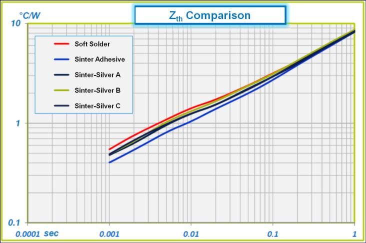
24 9 December, 2018Conductive Adhesives II
Advantages
Organic resin improves adhesion to different types of chip backside metals and leadframe platings.
Same or better mechanical, thermal, and electrical properties compared to solder, similar to sintered silver.
Commonly used die bond equipment can be used for dispensing, chip placement, and curing of the material
(Drop-In Solution).
Can pass automotive environment stress test conditions (AEC-Q100, AEC-Q101) depending on package type
and die size.
Comparison of transient thermal resistance of Scanning acoustic microscopy shows
highly silver filled adhesive vs. high-lead soft no delamination of die attach after
solder and sintered silver materials. 2000cycles TC -50°C / +150°C.
25 9 December, 2018Conductive Adhesives III
Limitations
Materials contain solvents to improve rheology for dispensing. This requires careful handling and control of the
manufacturing process. It also bears a risk of leadframe and die surface contamination.
Material cost is higher compared to standard adhesives and solder alloy.
Process window (bond line thickness, curing conditions) has to be determined for every die size.
Maximum die size (~50 mm²) strongly depends on package design and bill of materials. Backside metal is required.
Materials with sintered structure have high elastic modulus causing mechanical stresses and higher delamination risk.
Limitation seen for high power devices and moisture sensitivity level greater than MSL3/260°C.
Material usage only possible for die thickness >120 µm for the moment.
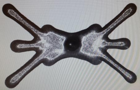
Dispense
Patterns
Visible solvent bleed out
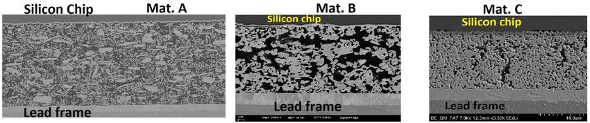
Scanning acoustic microscopy shows
delamination of large power transistor die
attach after 1000 th. cycles -50°C / +150°C
No solvent bleed out
Scanning acoustic microscopy of an as-
cured good part: apparent inhomogeneity
detected
26 9 December, 2018Ag Sintering I – Overview
Principle
Ag-sinter pastes: Ag particles (µm- and/or nm-scale) with organic coating, dispersants, & sintering
promoters
Dispense, pick & place die, pressureless sintering in N2 or air in box oven
Resulting die-attach layer is a porous network of pure, sintered Ag
Advantages
Better thermal and electrical performance than Pb-solder possible
Disadvantages
No self-alignment as with solder wetting
nm-scale Ag particles are at risk of being banned
New concept in molded packaging - no prior knowledge of feasibility, reliability or physics of failure
Production equipment changes might be needed (low-O2 ovens?)
Elevated risks
Limitations found in die area/thickness, lead frame & die finishes
Potential reliability issues: cracking (rigidity), delamination or bond lift (organic contamination,
thickness reduction due to continued sintering), interface degradation or electromigration of Ag
(O2 or humidity penetration, un-sintered Ag particles in die-attach layer)
27 9 December, 2018Ag Sintering II – Assembly
Dispensability and
staging time are
improving, long run
workability data not
available
Voiding is improving
Process control issue:
C-SAM scans are difficult
to interpret
Bond line density
differences should be
Die edge Die center
improved
Reduction of un-sintered
Ag particles is improving
28 9 December, 2018Ag Sintering III – 0-hr & Reliability Results
Oxidation and/or delamination of interfaces is common, even Die Delamination
at 0-hr, lowering adhesion and electrical & thermal performance.
Potential solutions (not yet proven):
Reduce oxygen content in atmosphere during curing
Change paste formulation to allow for lower sintering temperature or less
interaction with back-side metallization Ag-sinter material
Change back-side metallization
In cases with no delamination, high DSS (20 N/mm2) and good Ag-sinter material
thermal performance can be obtained with Ag finishes
In-package electrical performance still lags Pb-solder Ag-plating
No test configuration has passed yet all required reliability tests
after MSL1 preconditioning LF
Copper oxide
Results after MSL3 preconditioning are better, with reduced cracking and
delamination
Recent results show further improvements, but:
still some delamination after temperature cycling and pressure pot /
autoclave tests
failures during biased tests (THB, HAST) are common
Physics of failure understanding missing/ongoing: already
porosity and bond line thickness changes seen
Die penetration test shows non-hermetic die attach (at least for ~1mm from
the edges of the die)
29 9 December, 2018TLPS materials I
Advantages
Fulfills many of the drop-in replacement
requirements for a paste
Better cost position compared to Ag sintering
solutions
Good electrical performance on Ag-plated
leadframes
Disadvantages
Medium metal content in die attach
Medium space rate, filled with Epoxy
New concept in molded packaging - no prior
knowledge of feasibility or reliability
Potential incompatibility for dies above 50 mm2
due to high modulus and delamination risk
Elevated risks
High risk of Cu oxidation if oxygen concentration
exceeds 300 ppm during sintering under nitrogen
Potential reliability issues: Kirkendall voids form
during IMC growth at 175°C during HTSL
30 9 December, 2018TLPS materials II
The hybrid material showed a 1:1 metal-to-
resin ratio. The spaces between metal
structures are filled with epoxy resin material.
The reflow process is very critical and has to
be further optimized, the reflow profile seems
to be product-specific
Low maturity, more reliability data are
needed.
Results are package / leadframe material
dependent. A low metal / epoxy ratio is
needed to survive reliability, at the expense of
reduced thermal performance
Shear values at 260°C are low
Strong brittle intermetallic phase Metal material
growth with Cu
Epoxy material
Potential usage for SIP and clip packages
Thin die (thicknessAlternative Solders I
Properties to be considered
Robust manufacturing process
Repeatable solder application
Zn based alloy reference
Stable wetting angle
Surface compatibility (chip backside, lf
finish)
Reliability
Voiding / cracking / disruption after stress
Growth of brittle intermetallics
at high temperature
Disruption during temperature cycling
32 9 December, 2018Alternative Solders II
Zn-based Alloys
Material currently only available in wire form
Low wettability makes the use of special equipment necessary
(capability for mass production open)
Process temperature very high (above 410 °C) => high risk for incompatibility with chip
technologies
Growth of brittle intermetallics at high temperature limits reliability
New formulations demonstrate lower mechanical stress and reduced die cracking.
Improved reliability expected for dieKey Performance Indicators I
Comparison of competing Technologies
• DA5 now uses a new rating
system with revised criteria
(Pb based solder reference
set to 5 for all criteria) for
the technology comparison
• DA5 assessment refers to
best tested material in
class
• DA5 assessment only valid
for die thickness > 120 µm
34 9 December, 2018Key Performance Indicators II
Comparison of competing Technologies
• DA5 now uses a new rating
system with revised criteria
(Pb based solder reference
set to 5 for all criteria) for
the technology comparison
• DA5 assessment refers to
best tested material in
class
• DA5 assessment only valid
for die thickness > 120 µm
35 9 December, 2018Key Performance Indicators III
Comparison of competing Technologies
• DA5 now uses a new rating
system with revised criteria
(Pb based solder reference
set to 5 for all criteria) for
the technology comparison
• DA5 assessment refers to
best tested material in
class
• DA5 assessment only valid
for die thickness > 120 µm
36 9 December, 2018Key Performance Indicators IV
Comparison of competing Technologies
• DA5 now uses a new rating
system with revised criteria
(Pb based solder reference
set to 5 for all criteria) for
the technology comparison
• DA5 assessment refers to
best tested material in
class
• DA5 assessment only valid
for die thickness > 120 µm
37 9 December, 2018Agenda
Motivation: Environmental and health endangerment of lead
Situation: Lead & the use in Electronics
Status on legislation
DA5 Structure and Project:
Cooperations and partners
Requirements, Applications and Approaches for possible solutions
Results
Timeline and Conclusion
38 9 December, 2018DA5 Timeline (Overview/Milestones) I
12th F2F
Technology review & Supplier feedback Neubiberg
1st F2F 2ndF2F 3rd F2F 4th F2F 5th F2F 6th F2F 7th F2F 8th F2F 9th F2F 10th F2F 11th F2F 13th F2F
Sibiu Reutlingen Agrate Regensburg Munich Munich Nijmegen Reutlingen Agrate Regensburg Munich Nijmegen
General project activities Report FtF Munich
Reports
conf. "HiSold-Ro" Dr. Deubzer Dr. Deubzer
Dr. Deubzer
review of academia efforts
start of NDA signature Press Project plan project plan project plan project plan project plan project plan project plan
cooperation release review review review review review review review
Q1 Q2 Q3 Q4 Q1 Q2 Q3 Q4 Q1 Q2 Q3 Q4 Q1 Q2 Q3 Q4 Q1 Q2 Q3 Q4
2009 2010 2011 2012 2013
Technology review & Supplier feedback
14th F2F 15th F2F 16th F2F 17th F2F 18th F2F 19th F2F 20th F2F 21st F2F 22nd F2F 23rd F2F 24th F2F 25th F2F 26th F2F 27th F2F 28th F2F
Catania Reutlingen Regensburg Munich Munich NijmegenReutlingen CataniaRegensburg Munich Munich Nijmegen Hamburg Catania Regensburg
General project review activities
12.-15.11.18
last meeting
project plan project plan Supplier meetings with potential material freeze
review review
Q1 Q2 Q3 Q4 Q1 Q2 Q3 Q4 Q1 Q2 Q3 Q4 Q1 Q2 Q3 Q4 Q1 Q2 Q3 Q4
2014 2015 2016 2017 2018
39 9 December, 2018DA5 Timeline (Overview/Milestones) II
Technology review & Supplier feedback
29th F2F
Reutlingen
General project activities
18.-21.03.19
next meeting
Supplier meeting with potential material freeze
Q1 Q2 Q3 Q4 Q1 Q2 Q3 Q4 Q1 Q2 Q3 Q4 Q1 Q2 Q3 Q4 Q1 Q2 Q3 Q4
2019 2020 2021 2022 2023
40 9 December, 2018Substitute
DA5 Material(s) for
- Automotive High-LeadProcess(ELV)
Release Solders
DA Material Semiconductor Electronic
Package Vehicle
Technology Technology Component Control Unit
chain
Lead-free Lead-free
Die Attach Package Lead-free Lead-free Lead-free
Material Technology Component ECU Vehicle
Material freeze
Prototype Supply
typ. 2 years typ. 2 years typ. 2 years
type
DA5 release
DA Material scope Package
Development Development
additional time required
Assessment until product is commercially available
Physics of failure iterative
Workability, Reliability
Manufacturability
process
Supply
chain
Material Assembly Semiconductor Automotive Carmaker
Supplier Company Tier1 OEM
41 9 December, 2018Substitute
DA5 Material(s)
- Industrial for High-Lead
Release Solders
Process(RoHS)
DA Material Package Semiconductor Customer Application
Technology Technology Component
chain
Lead-free Lead-free
Die Attach Package Lead-free Lead-free
Material Technology Component Product
Material freeze
Prototype Supply
typ. 1 ½ years typ. 1 ½ years
type
DA5 release
DA Material scope Package
Development Development
additional time required
Assessment until product is commercially available
Physics of failure iterative
Workability, Reliability
Manufacturability
process
Supply
chain
Material Assembly Semiconductor
Supplier Company System Supplier
42 9 December, 2018Conclusion
Today’s lead-free material technologies for semiconductor applications (die attach) are not
ready to substitute Leaded High Melting Temperature Solders as drop-in solution.
Substantial development efforts have been running for more than 9,5 years.
While the DA5 consortium has not yet found a reliable lead-free package technology
for power semiconductor components, the research is promising for long-term
solutions.
Material evaluations continue in close cooperation with material suppliers, but
semiconductor component qualifications, material supplier conversions and equipment
conversions can only begin after a reliable lead-free package technology for replacement is
available.
Customer qualifications (TIER1 and OEM) and supply chain conversion / ramp can
only begin after package technology and semiconductor component qualification.
No single drop-in lead-free solution is in sight! Different applications will need different
solutions. It’s likely that some application fields will not be covered by lead-free solutions and
therefore need continued exemption.
Based on current status, DA5 cannot predict a date for customer sampling. As shown
in the previous two slides, the release process will take a substantial amount of time.
43 9 December, 2018Contact Information
Speaker of the DA5 consortium:
Bodo Eilken
Infineon Technologies AG
Email: bodo.eilken@infineon.com
DA5 customer presentation:
http://www.infineon.com/da5customerpresentation
The full specification document “DA5 Die-Attach Material
Requirement Specification” is available upon request at
DA5, see contact above.
44 9 December, 2018You can also read