Design and vehicle integration challenges for autonomous vehicle LIDARs
←
→
Page content transcription
If your browser does not render page correctly, please read the page content below

Siemens Digital Industries Software

  Design and vehicle
  integration challenges for
  autonomous vehicle LIDARs

Executive summary
With announcements from a large number of automakers to commercialize
autonomous cars by 2021, number and variety of sensors in vehicles are
poised to grow significantly posing new challenges for vehicle engineering
for automakers and suppliers. At the same time, designing for harsh automo-
tive environments with significantly higher reliability and safety require-
ments is a new challenge for many electronics companies who have an
opportunity to disrupt the automotive industry. Design, performance and
reliability of LIDARs, a key sensor critical to offer a robust 360° vision to
autonomous cars, are impacted by its thermal behavior. Simcenter’s elec-
tronics thermal characterization and simulation tools and their connectivity
with electronics design and layout software offer the functionality and accu-
racy of simulation that engineers can rely on to address such challenges.

John Wilson                            Puneet Sinha, PhD
Technical marketing engineer           Automotive

                                                   siemens.com/simcenter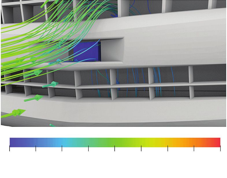
White paper | Design and vehicle integration challenges for autonomous vehicle LIDARs

Introduction

Reliable and cost-effective 360° vision creation, enabled     Design goals for LIDARs (solid-state or mechanical rotat-
by various vision and non-vision sensors, is at the heart     ing ones) are largely centered on size and cost reduc-
of development and commercialization of autonomous            tion without sacrificing (or increasing) range and reso-
vehicles. With the strong push for ADAS and autono-           lution. Increase in optical power benefits LIDAR range
mous vehicles, sensor market is projected to grow from        whereas integration of multiple light emitters and
$3 billion in 2015 to $35 billion by 2030 [1]. One of the     detectors on single monolithic chip sets and higher
key autonomous functionality-enabling sensor is LIDAR         signal processing improves resolution. These design
(Light Detection and Ranging) that was first used in the      factors combined with desired small form factors may
concept vehicles competing in DARPA (Defense                  cause significant heat buildup that may be detrimental
Advanced Research Project Agency) Grand Challenge for         to performance and durability of LIDARs. This may deter
autonomous vehicles [2]. LIDARs rely on time of flight        LIDAR size (and cost) reduction efforts. Additionally,
measurement for emitted light from laser diodes to be         LIDARs when integrated in vehicles must function reli-
detected by receivers after reflecting back from objects      ably in an automotive environment and in all-weather
in its path, and thus provide highly accurate informa-        conditions. Vehicle mounting location may further
tion not only about object distance but also offer 3D         present additional thermal challenges that sensor
information on object width and height.                       designers will need to account for while designing
                                                              sensors. The fact that different auto makers are looking
One of the early pioneers of LIDAR technology is
                                                              to integrate LIDARs in different parts of vehicle body,
Velodyne that introduced mechanical rotating LIDARs to
                                                              for instance side bumpers, front grill, headlights or
offer 360° vision. The mechanical rotating LIDARs are
                                                              taillights etc, further enhances design complexity for
the most distinguishing visible hardware on the vehicle
                                                              sensor vendors.
bodies for the autonomous test fleet on the road today.
Although such LIDARs provide 360° view with very high         This white paper is aimed at highlighting thermal-driven
resolution and long range (up to 200 m), high cost is a       design challenges for LIDARs as well as impact of vehi-
key deterrent for these LIDARs to be part of commer-          cle integration strategy on reliability in real-world oper-
cially-viable autonomous vehicles. Although in recent         ation. Underlying thermal issues resemble that in any
years, some companies, most notably Waymo [3], have           consumer electronics, however, for LIDARs and other
made significant advances to significantly reduce cost        autonomous vehicle sensors unique challenges arise
of these mechanical rotating LIDARs. Additionally, large      because of much harsher automotive environment and
size and potential reliability issues due to mechanical       the associated reliability and safety issues with these
parts, pose additional challenges for vehicle integration.    sensors. We’ll showcase how Simcenter’s EDA-centric
Due to these issues, industry is moving towards solid-        electronic cooling simulation software can be exploited
state LIDARs which promise to be in the $100-$250             by sensor vendors and Auto OEMs alike to account for
LIDAR price point at large scale volume. Solid-state          these challenges. For sake of consciousness, we’ll take a
LIDARs don’t have costly electric motors as used in           generic solid-state LIDAR example but the challenges
mechanical rotating LIDARs thus offer more cost-effec-        highlighted here apply equally to mechanical rotating
tiveness but suffer from limited field of view (FoV) and      LIDARs as well. Key takeaway message for readers is
lower range/resolution. Multiple solid-state LIDARS will      that thermally-conscious designs for LIDAR signal pro-
be needed to be integrated in autonomous vehicle. A           cessing electronics as well as for their enclosures, while
large number of companies developing solid-state              taking into account their vehicle integration locations,
LIDARs are pursuing innovative emitter/detector tech-         is critical to ensure desired size, cost, performance and
nologies to improve range and resolution as well as           life goals are met.
component and functionality consolidation to achieve
desired miniaturization.

Siemens Digital Industries Software                                                                                                  2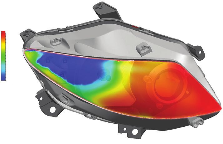
White paper | Design and vehicle integration challenges for autonomous vehicle LIDARs
Thermal-driven challenges for solid-state
LIDARs
Thermal design of electronic systems in automotive As the electrical and
applications, such as LIDAR, present common as well as mechanical design
a number of unique challenges. Any thermal design of evolves, the thermal
electronic systems involves ensuring that the critical IC design is refined in
components operate within the specified temperature parallel to provide
ranges allowing the system to provide sustainable and clear indication to
reliable performance. Thermal design of electronic what designs should
systems that are deployed in locations that allow for be prototyped and
human contact must also include the outer enclosure tested. During this
temperature as a design constraint to prevent harm phase, Simcenter’s
when touched. There are situations where the external thermal simulation
temperature is further limited by a perceived rather tools and its seams- Figure 2: Post-CAD model of LIDAR system
than the safe touch temperature. If an external surface less connectivity with with detailed components on PCB.
seems too warm this might lead the end user to con- electronics design
sider the system to be malfunctioning or even poorly tools (e.g. Simcenter’s Xpedition) and mechanical CAD
designed. Additionally, accurate LIDAR thermal analysis environment can be used for detailed thermal analysis
is critical because the measured distance vary with [5]. Figure 2 shows the thermal model of a prototype
operating temperature and require temperature com- candidate later in the electrical and mechanical design
pensation [4]. For LiDAR systems that use custom SoC phase.
(system on chip) ICs it is essential to predict operating
In addition to thermal design exploration and optimiza-
temperature and temperature gradients that contribute
tion for a LIDAR, it is important to evaluate design and
directly to reliability. The operating temperatures of
reliability implications for wide range of vehicle integra-
both the internal IC components and external surfaces
tion and use case scenarios. For instance, vehicle-
are influenced by the internal heat generation of IC
mounted LIDAR in hot sunny day where solar radiation
components, incident solar loading, surrounding tem-
can be a significant factor for heat buildup or potential
perature and air flow, and the thermal design.
contribution of forced convective cooling for vehicle-
Thermal design begins mounted LIDAR when vehicle is being driven. In addi-
well before any prototyp- tion, transient thermal behavior accounting for vehicle
ing and ideally when the driving scenarios can allow engineers to determine
system is first architected. impact of temperature transients and the time to reach
If thermal design is con- a critical temperature condition. These simulation-
sidered prior to, and in driven analysis, from early prototyping stages, empow-
parallel with electrical ers LIDAR designers to account for various performance
and mechanical, the and life limiting factors in their design and optimization
overall design process is analysis.
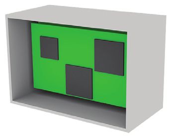
shortened and results in Figure 1: Pre-CAD model of LIDAR
system. In the next section some of the typical thermal design
a more robust product
options will be explored for a solid-state LIDAR system.
design. Thermal analysis
early in the design process can quickly eliminate some
options while indicating what designs show promise.
Figure 1 shows a conceptual thermal model used to
explore design variables such as component layout.
Siemens Digital Industries Software 3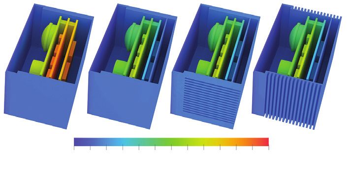
White paper | Design and vehicle integration challenges for autonomous vehicle LIDARs

Solid-state LIDAR design exploration

Consider the notional solid-state LIDAR system that          design can be terms as critical for a number of reasons
dissipates about 7W of heat which is distributed over        which include, high power dissipation, high power
three stacked printed circuit boards shown in figure 3.      density, or restrictive temperature limit. Critical ICs in a
The maximum power IC power dissipation is 1.5W for           LiDAR thermal design could be any SoC or temperature
the two components located on the rear printed circuit       sensitive sensor. Even at relatively low power dissipa-
board (top as shown in figure 3) and are referenced as       tions without the proper thermal design the device
the critical components. IC components in a thermal          performance can be limited with reduced reliability.

                                                                               3.0 W

                                                                               2.7 W

                                                                              1.08 W

Figure 3: LIDAR printed circuit boards.

Siemens Digital Industries Software                                                                                                 4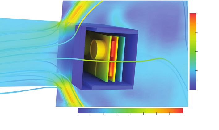
White paper | Design and vehicle integration challenges for autonomous vehicle LIDARs

LIDAR enclosure design considerations

The heat generated from the LIDAR components is                                 Whether the airflow is caused by buoyancy or external
convected and radiated from the external enclosure                              forces the fins are best designed for the specific system.
surfaces. When transferring heat through convection                             Simcenter’s design-centric thermal simulation allows
from a solid surface to a fluid, total surface area in                          parameters such as fin count, fin thickness, and fin
contact with the fluid plays a critical role. Design of this                    length to be optimized while either directly modeling or
additional surface area in the device is highly depen-                          including the effects of the overall system.
dent on the requirements for LIDAR integration in a
                                                                                Depending on the air speed across the fins, and the
vehicle. If the LIDAR is positioned such that it doesn’t
                                                                                surrounding radiating surfaces, thermal radiation from
benefit from the airflow caused by vehicle movement
                                                                                the external surfaces may be a significant mode of heat
then fins aligned vertically with gravity as shown in
                                                                                transfer. If a LIDAR is placed near components at high
figure 4a would typically be the recommended orienta-
                                                                                temperatures, it will absorb additional heat which will
tion. When the LIDAR system is exposed to forced air
                                                                                ultimately result in the LIDAR operating at elevated
from the environment the fins would be aligned with
                                                                                temperatures.
the predominant flow direction. In this example the air
movement is left to right resulting in the fin alignment                        Because the heat transfer from the LIDAR is influenced
shown in figure 4b.                                                             directly by how and where it is integrated in a vehicle, it
                                                                                is advisable to perform the enclosure thermal design
                                                                                while including the vehicle integration location and
                                                                                associated effects. When designing the fins the thermal
                                                                                performance is a primary concern but must be consid-
                                                                                ered along with the weight, cost, and manufacturability
                                                                                of the enclosure design.

(a)                                     (b)

Figure 4: Lidar enclosure design with (a) side fins aligned vertically with
gravity, (b) aligned with system airflow.

Siemens Digital Industries Software                                                                                                                    5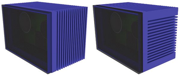
White paper | Design and vehicle integration challenges for autonomous vehicle LIDARs

LIDAR electronics thermal design

Appropriate thermal management of electronics board                            Solid-state LIDAR, described above, was simulated to
and critical ICs in the board is critical to ensure perfor-                    explore the relative benefits of the conduction and
mance and reliability. Small form factors, as desired for                      enclosure fin strategies. Simulations were done for a
automotive use, even for low power LIDARS can pose                             35°C natural convection environment. The enclosure
significant challenges for electronics thermal design.                         was assumed to have an emissivity of 0.9, for radiative
Heat generated from the internal LIDAR components is                           heat transfer. Table 1 summarizes thermal simulation
convected, conducted, and radiated to the enclosure                            results for solid-state LIDAR with the design options
internal surfaces. Heat transfer effectiveness for critical                    considered in this example. The critical IC temperature
IC components can be improved through increasing                               refers to the 1.5W component on the rear board with
heat transfer surface area or by adding new conduction                         the higher operating temperature. The results show
paths.                                                                         that including the conduction path reduced the critical
                                                                               IC temperature by 50 percent, from 104.8°C to 66.5°C.
Placing a heatsink or heat spreader on a device can
                                                                               This design change did result in an 18% enclosure tem-
lower the component temperature. Figure 5a shows a
                                                                               perature increase, from 57.4°C to 61.5°C. The addition
heat spreader mounted on the two 1.5W devices. Due
                                                                               of the conduction path reduced all of the temperatures
to the size constraints of a solid-state LIDAR, addition of
                                                                               with the LIDAR enclosure as shown in the figure 6 sur-
any significant heat transfer surface area via a heatsink
                                                                               face temperature plots. The results also indicate that
is problematic. It is a design alternative worth exploring
                                                                               the fins, in their current form, provide no significant
when only a small improvement in performance is
                                                                               benefit.
needed.
                                                                                Design                                    A                  B           C            D
(a)                                    (b)                                      External fins                            None           None         Horizontal   Vertical

                                                                                Direct conduction                         No                 Yes        Yes           Yes

                                                                                Critical IC temperature [°C]             104.8           66.5           66.6       66.5

                                                                                Enclosure temperature [°C]               57.4            61.5           61.7       61.5

Figure 5: Solid-state LIDAR electronics layout with (a) internal heat          Table 1: Solid-state LIDAR enclosure and critical IC temperature as a
spreaders, (b) conduction path from IC to enclosure for critical               function of design variables.
components.

When a significant reduction in temperature is needed
the addition of a direct conduction path to the outer
enclosure is a recommended design alternative.
Thermal conduction in solids such as Aluminum is much
more efficient that convection (and conduction)
through air. A conduction path from IC components to
the enclosure, as shown in figure 5b, will result in the                                   A                        B                            C                D
component temperatures operating at temperatures
much closer to the enclosure temperature. The temper-                                           50   55   60   65   70   75   80   85   90    95 100 105 110
ature reduction is influenced by a number of factors
                                                                                                                    Temperature [°C]
including the IC heat dissipation and the thermal resis-
tances between the IC and enclosure. While this design                         Figure 6: Surface temperature plots for LIDAR as a function of design
option has the benefit of reducing the IC temperature                          variables.
substantially, it can also lead to an elevated enclosure
temperature.

Siemens Digital Industries Software                                                                                                                                          6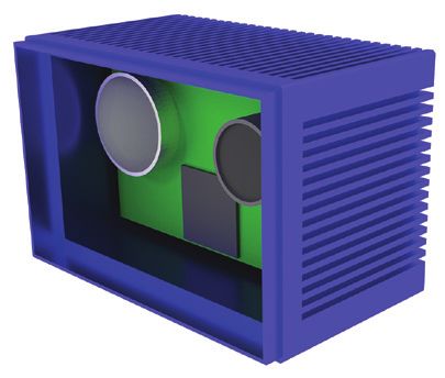
White paper | Design and vehicle integration challenges for autonomous vehicle LIDARs

LIDAR vehicle integration

While many thermal design parameters may be consid-                             Figure 8 shows a cross section of the LIDAR with a
ered with the LIDAR in stand-alone scenario as shown in                         speed contour and surface temperature plot. For clarity,
the previously described example, sensor designers                              vehicle body is not shown in this figure. Near the fin
must account for the effect of vehicle integration impli-                       area there is about three m/s of airflow which provides
cations from early design stages. Vehicle integration                           enough convective cooling as seen by the enclosure
introduces two important considerations for thermal                             surface temperatures slightly above the ambient tem-
design: 1) solar radiation load on LIDAR depending on                           perature of 35°C. The internal component temperatures
its mounting location, and 2) additional active cooling                         range from 45°C to 75°C. There was a reduction in
due to forced convection while vehicle is being driven.                         critical IC temperature from 67°C, in the natural con-
Answers to questions regarding the expected amount of                           vection study, to 45°C when simulating in the 10 m/s
airflow or the influence of neighboring systems can                             environment. When not considering the environment
only be answered by a thermal-airflow model that                                in the simulation there is a risk of either over design, or
includes the additional information. Let’s consider a                           under design. Either way there is a risk of uncertainty in
scenario where a solid-state LIDAR (design C from                               the thermal design that can be avoided if the thermal
figure 6) is mounted in the front grill of a vehicle, as                        design considers external influences.
shown in figure 7. Ambient temperature in this case is
35°C and for simplicity of analysis we are considering
vehicle is driven at a constant speed of 10 m/s. An inci-                                                                                           7.5e+01

dent solar load of 300 W/m2 with 50% absorption was                                                                                                 70

also included.                                                                                                                                      65

                                                                                                                                                    60

                                                                                                                                                          Temperature [°C]
                                                                                                                                                    55

                                                                                                                                                    50

                                                                                                                                                    45

                                                                                                                                                    40

                                                                                                                                                    3.5e+01

                                                                                                         0    1   2    3     4      5   6   7   8
                                                                                                                       Velocity [m/s]

                                                                                Figure 8: Front grill mounted Solid-State LIDAR model enlarged.

                                                                                The Impact of solar radiation for front-grill mounted
                                                                                LIDAR was minimal. However, for LIDARs that are
                                                                                mounted on the vehicle roof or other areas directly
  0       1        2        3         4          5     6       7          8
                                                                                exposed to sun, this can’t be neglected. A wide range of
                                                                                analyses for LIDAR thermal behavior as a function of its
                                Velocity [m/s]
                                                                                mounting location can be easily carried out using the
Figure 7: Front grill mounted Solid-State LIDAR [design C] model.
                                                                                framework described here.

Siemens Digital Industries Software                                                                                                                           7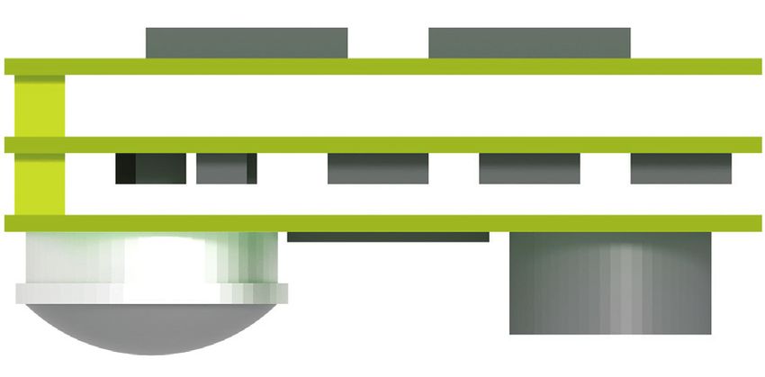
White paper | Design and vehicle integration challenges for autonomous vehicle LIDARs

Testing autonomous vehicle functionality in extreme           Another benefit of thermal simulation of vehicle inte-
hot (for instance, Death Valley, Arizona) and cold            grated LIDARs, as shown in this article, is that using the
(Minnesota winters) weather conditions is a critical part     temperature response, sensor engineers can develop
of vehicle verification and validation. To ensure LIDARs      appropriate temperature compensation algorithms for
(and other sensors and autonomous functionality-              LIDAR range and resolution estimates.
enabling electronics) can function in extremely hot and
cold weather conditions, thermal simulation of vehicle
integrated LIDARs will be extremely useful for both
sensor vendors and auto OEMs. Using the framework
showcased in this section, engineers can simulate ther-
mal behavior and its impact on vehicle functionality for
any number of real-world traffic scenarios and avoid
heavily relying on wind tunnel testing and/or full-vehi-
cle testing.

LIDAR integration in headlights and tail lights

In the last couple of years, solid-state LIDAR integration
in headlights and tail lights have been proposed [6].
LIDAR integration in head or tail lights offers not just
better vehicle aesthetics but also LIDAR protection from        5.00
                                                                4.67
                                                                4.33

dust, dirt, water However, a unique set of challenges
                                                                4.00
                                                                3.67
                                                                3.33

arise for LIDAR and headlight design. Integration chal-
                                                                3.00
                                                                2.67
                                                                2.33
                                                                2.00

lenges include heat from neighboring lamps, and con-            1.67
                                                                1.33
                                                                1.00

densation or icing on the headlight lens that will nega-
                                                                0.67
                                                                0.33
                                                                0

tively impact LIDAR performance. LIDAR developers and         Film thickness
                                                              [micrometer]
headlight designers alike can leverage Simcenter’s
CAD-embedded headlight simulation capabilities [7, 8]
to address these integration challenges. For instance,
figure 9 shows a transient simulation for water conden-
sation on exterior glass of an automotive LED headlight.
Transients and non-uniform distribution of water (and
                                                              Figure 9: CAD-embedded automotive headlight simulation for transient
similarly ice) film strongly depends on headlight design.     defogging analysis.
In contrast to today’s vehicle, transients of headlight
defogging and de-icing has strong implications for
autonomous vehicles with LIDAR integrated headlights.
We’ll discuss LIDAR integrated headlights design in a
future white paper.

Siemens Digital Industries Software                                                                                                  8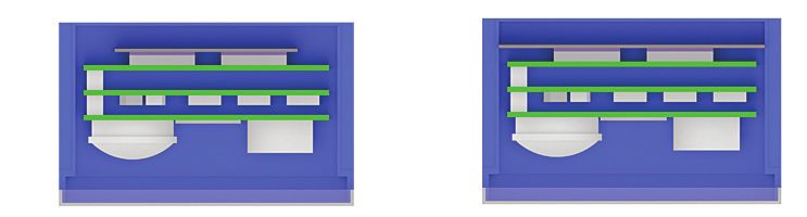
White paper | Design and vehicle integration challenges for autonomous vehicle LIDARs

Integration of thermal characterization
testing with simulation with simulation
for accurate predictions

A key challenge for accurate electronics thermal simula-                     measurements through an automated process.
tion is the lack of reliable thermal properties. We                          Benchmarking electronics thermal simulation with this
empower engineers to overcome this bottleneck by                             workflow against measured data has shown
Siemens Digital Industries Software                                                         About Siemens Digital Industries Software
                                                                                            Siemens Digital Industries Software is driving transfor-
Headquarters                                                                                mation to enable a digital enterprise where engineering,
Granite Park One                                                                            manufacturing and electronics design meet tomorrow.
5800 Granite Parkway                                                                        Our solutions help companies of all sizes create and
Suite 600                                                                                   leverage digital twins that provide organizations with
Plano, TX 75024                                                                             new insights, opportunities and levels of automation to
USA                                                                                         drive innovation. For more information on Siemens
+1 972 987 3000                                                                             Digital Industries Software products and services, visit
                                                                                            siemens.com/software or follow us on LinkedIn, Twitter,
Americas                                                                                    Facebook and Instagram. Siemens Digital Industries
Granite Park One                                                                            Software – Where today meets tomorrow.
5800 Granite Parkway
Suite 600
Plano, TX 75024
USA
+1 314 264 8499

Europe
Stephenson House
Sir William Siemens Square
Frimley, Camberley
Surrey, GU16 8QD
+44 (0) 1276 413200

Asia-Pacific
Unit 901-902, 9/F
Tower B, Manulife Financial Centre
223-231 Wai Yip Street, Kwun Tong
Kowloon, Hong Kong
+852 2230 3333

siemens.com/software
© 2018 Siemens. A list of relevant Siemens trademarks can be found here. Other trademarks
belong to their respective owners.
74406-C14 10/18 H
You can also read