TU0778 Tutorial PolarFire FPGA: Building a Cortex-M1 Processor Subsystem - Microsemi
←
→
Page content transcription
If your browser does not render page correctly, please read the page content below
TU0778
Tutorial
PolarFire FPGA: Building a Cortex-M1 Processor
Subsystem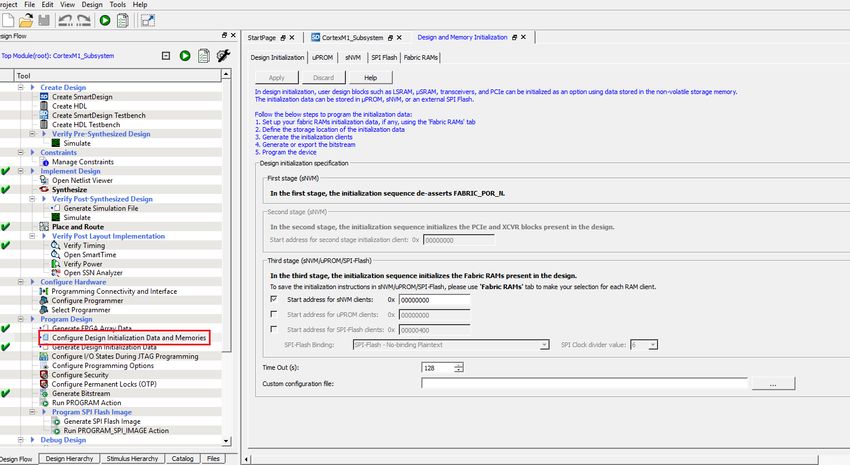
Microsemi makes no warranty, representation, or guarantee regarding the information contained herein or the suitability of
                                              its products and services for any particular purpose, nor does Microsemi assume any liability whatsoever arising out of the
                                              application or use of any product or circuit. The products sold hereunder and any other products sold by Microsemi have
                                              been subject to limited testing and should not be used in conjunction with mission-critical equipment or applications. Any
                                              performance specifications are believed to be reliable but are not verified, and Buyer must conduct and complete all
                                              performance and other testing of the products, alone and together with, or installed in, any end-products. Buyer shall not
Microsemi Headquarters
                                              rely on any data and performance specifications or parameters provided by Microsemi. It is the Buyer’s responsibility to
One Enterprise, Aliso Viejo,                  independently determine suitability of any products and to test and verify the same. The information provided by Microsemi
CA 92656 USA                                  hereunder is provided “as is, where is” and with all faults, and the entire risk associated with such information is entirely
Within the USA: +1 (800) 713-4113             with the Buyer. Microsemi does not grant, explicitly or implicitly, to any party any patent rights, licenses, or any other IP
Outside the USA: +1 (949) 380-6100            rights, whether with regard to such information itself or anything described by such information. Information provided in this
Sales: +1 (949) 380-6136                      document is proprietary to Microsemi, and Microsemi reserves the right to make any changes to the information in this
Fax: +1 (949) 215-4996                        document or to any products and services at any time without notice.
Email: sales.support@microsemi.com
www.microsemi.com
                                              About Microsemi
©2021 Microsemi, a wholly owned               Microsemi, a wholly owned subsidiary of Microchip Technology Inc. (Nasdaq: MCHP), offers a comprehensive portfolio of
subsidiary of Microchip Technology Inc. All   semiconductor and system solutions for aerospace & defense, communications, data center and industrial markets.
rights reserved. Microsemi and the            Products include high-performance and radiation-hardened analog mixed-signal integrated circuits, FPGAs, SoCs and
Microsemi logo are registered trademarks of   ASICs; power management products; timing and synchronization devices and precise time solutions, setting the world's
Microsemi Corporation. All other trademarks   standard for time; voice processing devices; RF solutions; discrete components; enterprise storage and communication
and service marks are the property of their   solutions, security technologies and scalable anti-tamper products; Ethernet solutions; Power-over-Ethernet ICs and
                                              midspans; as well as custom design capabilities and services. Learn more at www.microsemi.com.
respective owners.

                                                                                                                                                           50200778. 7.0 1/21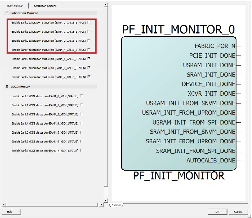
Contents

1 Revision History . . . . . . . . . . . . . . . . . . . . . . . . . . . . . . . . . . . . . . . . . . . . . . . . . . . . . 1
    1.1       Revision 7.0        .......................................................................1
    1.2       Revision 6.0        .......................................................................1
    1.3       Revision 5.0        .......................................................................1
    1.4       Revision 4.0        .......................................................................1
    1.5       Revision 3.0        .......................................................................1
    1.6       Revision 2.0        .......................................................................1
    1.7       Revision 1.0        .......................................................................1

2 Building a Cortex-M1 Processor Subsystem . . . . . . . . . . . . . . . . . . . . . . . . . . . . . . . 2
    2.1       Requirements . . . . . . . . . . . . . . . . . . . . . . . . . . . . . . . . . . . . . . . . . . . . . . . . . . . . . . . . . . . . . . . . . . . . . . 2
    2.2       Prerequisites . . . . . . . . . . . . . . . . . . . . . . . . . . . . . . . . . . . . . . . . . . . . . . . . . . . . . . . . . . . . . . . . . . . . . . 3
    2.3       Creating a Cortex-M1 Processor Subsystem . . . . . . . . . . . . . . . . . . . . . . . . . . . . . . . . . . . . . . . . . . . . . . 3
              2.3.1    Creating a Libero SoC Project . . . . . . . . . . . . . . . . . . . . . . . . . . . . . . . . . . . . . . . . . . . . . . . . . . 4
              2.3.2    Creating a New SmartDesign Component . . . . . . . . . . . . . . . . . . . . . . . . . . . . . . . . . . . . . . . . 7
              2.3.3    Instantiating the IP Cores in SmartDesign . . . . . . . . . . . . . . . . . . . . . . . . . . . . . . . . . . . . . . . . . 7
              2.3.4    Connecting IP Blocks in SmartDesign . . . . . . . . . . . . . . . . . . . . . . . . . . . . . . . . . . . . . . . . . . . 15
              2.3.5    Generating SmartDesign Component . . . . . . . . . . . . . . . . . . . . . . . . . . . . . . . . . . . . . . . . . . . 17
              2.3.6    Managing Timing Constraints . . . . . . . . . . . . . . . . . . . . . . . . . . . . . . . . . . . . . . . . . . . . . . . . . 18
              2.3.7    Running Libero Design Flow . . . . . . . . . . . . . . . . . . . . . . . . . . . . . . . . . . . . . . . . . . . . . . . . . . 18

3 Creating User Application Using SoftConsole . . . . . . . . . . . . . . . . . . . . . . . . . . . . . 29
    3.1       Creating a Cortex-M1 Project . . . . . . . . . . . . . . . . . . . . . . . . . . . . . . . . . . . . . . . . . . . . . . . . . . . . . . . .           29
    3.2       Downloading the Firmware Drivers . . . . . . . . . . . . . . . . . . . . . . . . . . . . . . . . . . . . . . . . . . . . . . . . . . . .               31
    3.3       Importing the Firmware Drivers . . . . . . . . . . . . . . . . . . . . . . . . . . . . . . . . . . . . . . . . . . . . . . . . . . . . . . .           33
    3.4       Creating the main.c File . . . . . . . . . . . . . . . . . . . . . . . . . . . . . . . . . . . . . . . . . . . . . . . . . . . . . . . . . . . . .     34
    3.5       Configuring the Cortex-M1 Project . . . . . . . . . . . . . . . . . . . . . . . . . . . . . . . . . . . . . . . . . . . . . . . . . . . . .            35
    3.6       Mapping Memory and Peripheral Addresses . . . . . . . . . . . . . . . . . . . . . . . . . . . . . . . . . . . . . . . . . . . . .                      40
    3.7       Setting the UART Baud Rate . . . . . . . . . . . . . . . . . . . . . . . . . . . . . . . . . . . . . . . . . . . . . . . . . . . . . . . . .           41
    3.8       Building the User Application in Release Mode . . . . . . . . . . . . . . . . . . . . . . . . . . . . . . . . . . . . . . . . . . .                    42
    3.9       Building In Debug Mode and Debugging the User Application . . . . . . . . . . . . . . . . . . . . . . . . . . . . . . .                                44

4 Appendix 1: Running the TCL Script . . . . . . . . . . . . . . . . . . . . . . . . . . . . . . . . . . . . 51
5 Appendix 2: References . . . . . . . . . . . . . . . . . . . . . . . . . . . . . . . . . . . . . . . . . . . . . 52

                                                Microsemi Proprietary TU0778 Revision 7.0                                                                             iii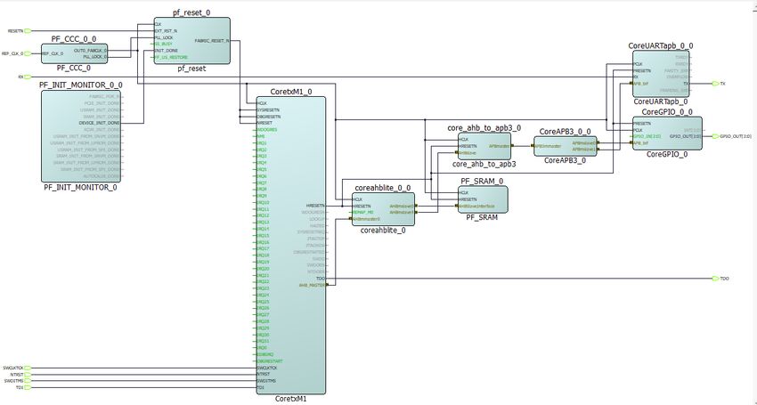
Figures

 Figure 1    Add Core to Vault . . . . . . . . . . . . . . . . . . . . . . . . . . . . . . . . . . . . . . . . . . . . . . . . . . . . . . . . . . . . . . . 3
 Figure 2    Block Diagram . . . . . . . . . . . . . . . . . . . . . . . . . . . . . . . . . . . . . . . . . . . . . . . . . . . . . . . . . . . . . . . . . 4
 Figure 3    New Project Details . . . . . . . . . . . . . . . . . . . . . . . . . . . . . . . . . . . . . . . . . . . . . . . . . . . . . . . . . . . . . 5
 Figure 4    Device Selection . . . . . . . . . . . . . . . . . . . . . . . . . . . . . . . . . . . . . . . . . . . . . . . . . . . . . . . . . . . . . . . . 5
 Figure 5    Device Settings . . . . . . . . . . . . . . . . . . . . . . . . . . . . . . . . . . . . . . . . . . . . . . . . . . . . . . . . . . . . . . . . . 6
 Figure 6    Add Constraints Window . . . . . . . . . . . . . . . . . . . . . . . . . . . . . . . . . . . . . . . . . . . . . . . . . . . . . . . . . 6
 Figure 7    Create New SmartDesign . . . . . . . . . . . . . . . . . . . . . . . . . . . . . . . . . . . . . . . . . . . . . . . . . . . . . . . . . 7
 Figure 8    Instantiating PF_INIT_MONITOR . . . . . . . . . . . . . . . . . . . . . . . . . . . . . . . . . . . . . . . . . . . . . . . . . . . 8
 Figure 9    PF_CCC Clock Options . . . . . . . . . . . . . . . . . . . . . . . . . . . . . . . . . . . . . . . . . . . . . . . . . . . . . . . . . . 9
 Figure 10   PF_CCC Output Clocks . . . . . . . . . . . . . . . . . . . . . . . . . . . . . . . . . . . . . . . . . . . . . . . . . . . . . . . . . . 9
 Figure 11   CoreCORTEXM1 Configurator . . . . . . . . . . . . . . . . . . . . . . . . . . . . . . . . . . . . . . . . . . . . . . . . . . . . 10
 Figure 12   CoreAHBLite Configurator . . . . . . . . . . . . . . . . . . . . . . . . . . . . . . . . . . . . . . . . . . . . . . . . . . . . . . . 11
 Figure 13   PF_SRAM_AHBL_AXI Configurator . . . . . . . . . . . . . . . . . . . . . . . . . . . . . . . . . . . . . . . . . . . . . . . . 12
 Figure 14   CoreAPB3 Configurator . . . . . . . . . . . . . . . . . . . . . . . . . . . . . . . . . . . . . . . . . . . . . . . . . . . . . . . . . 13
 Figure 15   Core GPIO Configurator . . . . . . . . . . . . . . . . . . . . . . . . . . . . . . . . . . . . . . . . . . . . . . . . . . . . . . . . . 14
 Figure 16   CortexM1_Subsystem Without Connections . . . . . . . . . . . . . . . . . . . . . . . . . . . . . . . . . . . . . . . . . 14
 Figure 17   Connection Method . . . . . . . . . . . . . . . . . . . . . . . . . . . . . . . . . . . . . . . . . . . . . . . . . . . . . . . . . . . . . 15
 Figure 18   CortexM1_Subsystem With Connections . . . . . . . . . . . . . . . . . . . . . . . . . . . . . . . . . . . . . . . . . . . . 16
 Figure 19   Modify Memory Map Dialog Box- APB3 . . . . . . . . . . . . . . . . . . . . . . . . . . . . . . . . . . . . . . . . . . . . . 17
 Figure 20   Modify Memory Map Dialog Box- CoreAHBLite . . . . . . . . . . . . . . . . . . . . . . . . . . . . . . . . . . . . . . . 17
 Figure 21   Build Hierarchy option . . . . . . . . . . . . . . . . . . . . . . . . . . . . . . . . . . . . . . . . . . . . . . . . . . . . . . . . . . . 17
 Figure 22   Generate Component . . . . . . . . . . . . . . . . . . . . . . . . . . . . . . . . . . . . . . . . . . . . . . . . . . . . . . . . . . . 18
 Figure 23   Derived Constraints . . . . . . . . . . . . . . . . . . . . . . . . . . . . . . . . . . . . . . . . . . . . . . . . . . . . . . . . . . . . 18
 Figure 24   Synthesis Completion . . . . . . . . . . . . . . . . . . . . . . . . . . . . . . . . . . . . . . . . . . . . . . . . . . . . . . . . . . . 19
 Figure 25   Manage Constraints . . . . . . . . . . . . . . . . . . . . . . . . . . . . . . . . . . . . . . . . . . . . . . . . . . . . . . . . . . . . 19
 Figure 26   I/O Attributes . . . . . . . . . . . . . . . . . . . . . . . . . . . . . . . . . . . . . . . . . . . . . . . . . . . . . . . . . . . . . . . . . . 19
 Figure 27   Place and Route Completion . . . . . . . . . . . . . . . . . . . . . . . . . . . . . . . . . . . . . . . . . . . . . . . . . . . . . 20
 Figure 28   Verify Timing Completion . . . . . . . . . . . . . . . . . . . . . . . . . . . . . . . . . . . . . . . . . . . . . . . . . . . . . . . . 20
 Figure 29   FPGA Array Data Generated . . . . . . . . . . . . . . . . . . . . . . . . . . . . . . . . . . . . . . . . . . . . . . . . . . . . . 20
 Figure 30   Design and Memory Initialization . . . . . . . . . . . . . . . . . . . . . . . . . . . . . . . . . . . . . . . . . . . . . . . . . . 21
 Figure 31   Fabric RAMs Tab . . . . . . . . . . . . . . . . . . . . . . . . . . . . . . . . . . . . . . . . . . . . . . . . . . . . . . . . . . . . . . 22
 Figure 32   Edit Fabric RAM Initialization Client Dialog Box . . . . . . . . . . . . . . . . . . . . . . . . . . . . . . . . . . . . . . . 22
 Figure 33   Fabric RAM Content Applied . . . . . . . . . . . . . . . . . . . . . . . . . . . . . . . . . . . . . . . . . . . . . . . . . . . . . 22
 Figure 34   Generate Initialization Clients . . . . . . . . . . . . . . . . . . . . . . . . . . . . . . . . . . . . . . . . . . . . . . . . . . . . . 23
 Figure 35   Generate Design Initialization Data Status . . . . . . . . . . . . . . . . . . . . . . . . . . . . . . . . . . . . . . . . . . . 23
 Figure 36   sNVM Client Verification . . . . . . . . . . . . . . . . . . . . . . . . . . . . . . . . . . . . . . . . . . . . . . . . . . . . . . . . . 24
 Figure 37   Generate Bitstream Completion . . . . . . . . . . . . . . . . . . . . . . . . . . . . . . . . . . . . . . . . . . . . . . . . . . . 24
 Figure 38   Board Setup . . . . . . . . . . . . . . . . . . . . . . . . . . . . . . . . . . . . . . . . . . . . . . . . . . . . . . . . . . . . . . . . . . 25
 Figure 39   COM Port Number . . . . . . . . . . . . . . . . . . . . . . . . . . . . . . . . . . . . . . . . . . . . . . . . . . . . . . . . . . . . . 26
 Figure 40   Select Serial as the Connection Type . . . . . . . . . . . . . . . . . . . . . . . . . . . . . . . . . . . . . . . . . . . . . . . 26
 Figure 41   PuTTY Configuration . . . . . . . . . . . . . . . . . . . . . . . . . . . . . . . . . . . . . . . . . . . . . . . . . . . . . . . . . . . 27
 Figure 42   Run Program Action Completion . . . . . . . . . . . . . . . . . . . . . . . . . . . . . . . . . . . . . . . . . . . . . . . . . . 27
 Figure 43   Hello World In Release Mode . . . . . . . . . . . . . . . . . . . . . . . . . . . . . . . . . . . . . . . . . . . . . . . . . . . . . 28
 Figure 44   Workspace Launcher . . . . . . . . . . . . . . . . . . . . . . . . . . . . . . . . . . . . . . . . . . . . . . . . . . . . . . . . . . . 29
 Figure 45   Creating New C Project . . . . . . . . . . . . . . . . . . . . . . . . . . . . . . . . . . . . . . . . . . . . . . . . . . . . . . . . . 29
 Figure 46   New Project Window . . . . . . . . . . . . . . . . . . . . . . . . . . . . . . . . . . . . . . . . . . . . . . . . . . . . . . . . . . . . 30
 Figure 47   C Project Window . . . . . . . . . . . . . . . . . . . . . . . . . . . . . . . . . . . . . . . . . . . . . . . . . . . . . . . . . . . . . . 30
 Figure 48   Empty Cortex-M1 Project . . . . . . . . . . . . . . . . . . . . . . . . . . . . . . . . . . . . . . . . . . . . . . . . . . . . . . . . 31
 Figure 49   Firmware Catalog Window . . . . . . . . . . . . . . . . . . . . . . . . . . . . . . . . . . . . . . . . . . . . . . . . . . . . . . . 31
 Figure 50   Generate Options . . . . . . . . . . . . . . . . . . . . . . . . . . . . . . . . . . . . . . . . . . . . . . . . . . . . . . . . . . . . . . 32
 Figure 51   CoreGPIO Files Report . . . . . . . . . . . . . . . . . . . . . . . . . . . . . . . . . . . . . . . . . . . . . . . . . . . . . . . . . . 32
 Figure 52   CoreUARTapb Files Report . . . . . . . . . . . . . . . . . . . . . . . . . . . . . . . . . . . . . . . . . . . . . . . . . . . . . . 32
 Figure 53   Import Option . . . . . . . . . . . . . . . . . . . . . . . . . . . . . . . . . . . . . . . . . . . . . . . . . . . . . . . . . . . . . . . . . 33
 Figure 54   Import Window . . . . . . . . . . . . . . . . . . . . . . . . . . . . . . . . . . . . . . . . . . . . . . . . . . . . . . . . . . . . . . . . 33

                                         Microsemi Proprietary TU0778 Revision 7.0                                                                             iv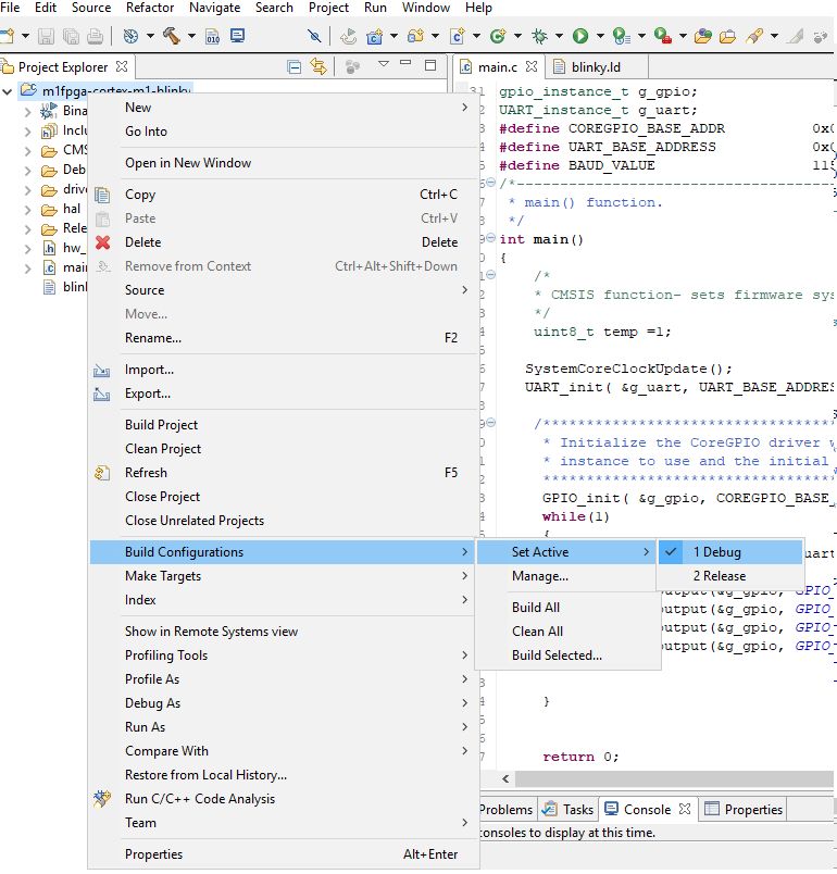
Figure 55   Import Window Continued . . . . . . . . . . . . . . . . . . . . . . . . . . . . . . . . . . . . . . . . . . . . . . . . . . . . . . .                34
Figure 56   Creating the main.c File . . . . . . . . . . . . . . . . . . . . . . . . . . . . . . . . . . . . . . . . . . . . . . . . . . . . . . . . .           34
Figure 57   The main.c file . . . . . . . . . . . . . . . . . . . . . . . . . . . . . . . . . . . . . . . . . . . . . . . . . . . . . . . . . . . . . . . .      35
Figure 58   All Configuration Setting . . . . . . . . . . . . . . . . . . . . . . . . . . . . . . . . . . . . . . . . . . . . . . . . . . . . . . . . .          35
Figure 59   Target Processor . . . . . . . . . . . . . . . . . . . . . . . . . . . . . . . . . . . . . . . . . . . . . . . . . . . . . . . . . . . . . .         36
Figure 60   Tool Settings Options . . . . . . . . . . . . . . . . . . . . . . . . . . . . . . . . . . . . . . . . . . . . . . . . . . . . . . . . . . .          36
Figure 61   Adding CoreGPIO Directory Path . . . . . . . . . . . . . . . . . . . . . . . . . . . . . . . . . . . . . . . . . . . . . . . . . .                   37
Figure 62   Adding the CoreGPIO Folder . . . . . . . . . . . . . . . . . . . . . . . . . . . . . . . . . . . . . . . . . . . . . . . . . . . . .                 37
Figure 63   CoreGPIO Path Added . . . . . . . . . . . . . . . . . . . . . . . . . . . . . . . . . . . . . . . . . . . . . . . . . . . . . . . . . .              37
Figure 64   Adding CMSIS and startup_gcc paths . . . . . . . . . . . . . . . . . . . . . . . . . . . . . . . . . . . . . . . . . . . . . .                       38
Figure 65   Adding HAL, CortexM1, and GNU Paths . . . . . . . . . . . . . . . . . . . . . . . . . . . . . . . . . . . . . . . . . . . .                          38
Figure 66   Miscellaneous Setting . . . . . . . . . . . . . . . . . . . . . . . . . . . . . . . . . . . . . . . . . . . . . . . . . . . . . . . . . . .          38
Figure 67   Mapping Successful . . . . . . . . . . . . . . . . . . . . . . . . . . . . . . . . . . . . . . . . . . . . . . . . . . . . . . . . . . . .           39
Figure 68   Mapping Linker Script . . . . . . . . . . . . . . . . . . . . . . . . . . . . . . . . . . . . . . . . . . . . . . . . . . . . . . . . . . .          39
Figure 69   GNU ARM Cross Create Flash Image Settings . . . . . . . . . . . . . . . . . . . . . . . . . . . . . . . . . . . . . . .                              40
Figure 70   Updated Linker Script . . . . . . . . . . . . . . . . . . . . . . . . . . . . . . . . . . . . . . . . . . . . . . . . . . . . . . . . . . .          40
Figure 71   Updated main.c File . . . . . . . . . . . . . . . . . . . . . . . . . . . . . . . . . . . . . . . . . . . . . . . . . . . . . . . . . . . .          41
Figure 72   Defining Baud Value . . . . . . . . . . . . . . . . . . . . . . . . . . . . . . . . . . . . . . . . . . . . . . . . . . . . . . . . . . . .          41
Figure 73   Build Configuration . . . . . . . . . . . . . . . . . . . . . . . . . . . . . . . . . . . . . . . . . . . . . . . . . . . . . . . . . . . . .        42
Figure 74   Build Project . . . . . . . . . . . . . . . . . . . . . . . . . . . . . . . . . . . . . . . . . . . . . . . . . . . . . . . . . . . . . . . . . .    42
Figure 75   Build Finished . . . . . . . . . . . . . . . . . . . . . . . . . . . . . . . . . . . . . . . . . . . . . . . . . . . . . . . . . . . . . . . . .     43
Figure 76   HEX File . . . . . . . . . . . . . . . . . . . . . . . . . . . . . . . . . . . . . . . . . . . . . . . . . . . . . . . . . . . . . . . . . . . . .   43
Figure 77   Build Configurations . . . . . . . . . . . . . . . . . . . . . . . . . . . . . . . . . . . . . . . . . . . . . . . . . . . . . . . . . . . .         44
Figure 78   Build Project . . . . . . . . . . . . . . . . . . . . . . . . . . . . . . . . . . . . . . . . . . . . . . . . . . . . . . . . . . . . . . . . . .    45
Figure 79   Debug Option . . . . . . . . . . . . . . . . . . . . . . . . . . . . . . . . . . . . . . . . . . . . . . . . . . . . . . . . . . . . . . . . .       46
Figure 80   Debug Configurations . . . . . . . . . . . . . . . . . . . . . . . . . . . . . . . . . . . . . . . . . . . . . . . . . . . . . . . . . . .           46
Figure 81   Program Selection . . . . . . . . . . . . . . . . . . . . . . . . . . . . . . . . . . . . . . . . . . . . . . . . . . . . . . . . . . . . .          47
Figure 82   Settings in the Debugger Tab . . . . . . . . . . . . . . . . . . . . . . . . . . . . . . . . . . . . . . . . . . . . . . . . . . . . .               47
Figure 83   Debug Settings- Startup Tab . . . . . . . . . . . . . . . . . . . . . . . . . . . . . . . . . . . . . . . . . . . . . . . . . . . . .                48
Figure 84   Confirm Perspective Switch Dialog Box . . . . . . . . . . . . . . . . . . . . . . . . . . . . . . . . . . . . . . . . . . . . .                      48
Figure 85   First Instruction in main.c . . . . . . . . . . . . . . . . . . . . . . . . . . . . . . . . . . . . . . . . . . . . . . . . . . . . . . . .          49
Figure 86   Resume Application Execution . . . . . . . . . . . . . . . . . . . . . . . . . . . . . . . . . . . . . . . . . . . . . . . . . . . .                 49
Figure 87   Hello World in Debug Mode . . . . . . . . . . . . . . . . . . . . . . . . . . . . . . . . . . . . . . . . . . . . . . . . . . . . . .                50
Figure 88   Cortex-M1 Register Values . . . . . . . . . . . . . . . . . . . . . . . . . . . . . . . . . . . . . . . . . . . . . . . . . . . . . . .              50

                                        Microsemi Proprietary TU0778 Revision 7.0                                                                                 v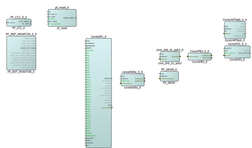
Tables

 Table 1   Tutorial Requirements . . . . . . . . . . . . . . . . . . . . . . . . . . . . . . . . . . . . . . . . . . . . . . . . . . . . . . . . . . . 2
 Table 2   Jumper Settings . . . . . . . . . . . . . . . . . . . . . . . . . . . . . . . . . . . . . . . . . . . . . . . . . . . . . . . . . . . . . . . 25

                                      Microsemi Proprietary TU0778 Revision 7.0                                                                         vi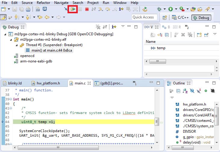
Revision History

1            Revision History

             The revision history describes the changes that were implemented in the document. The changes are
             listed by revision, starting with the current publication.

1.1          Revision 7.0
             Added Appendix 1: Running the TCL Script, page 51.

1.2          Revision 6.0
             The following is a summary of the changes made in this revision.
             •     Updated the document for Libero SoC v12.2.
             •     Removed the references to Libero version numbers.

1.3          Revision 5.0
             Updated the document for Libero® SoC v12.0.

1.4          Revision 4.0
             Updated the document for Libero SoC PolarFire v2.2 release.

1.5          Revision 3.0
             The following is a summary of the changes made in this revision.
             •     The document was updated for Libero SoC PolarFire v2.1.
             •     Replaced AND3 with CoreReset_PF throughout the document.
             •     Updated Connecting IP Blocks in SmartDesign, page 15.

1.6          Revision 2.0
             The document was updated for Libero SoC PolarFire v2.0.

1.7          Revision 1.0
             The first publication of this document.

                                     Microsemi Proprietary TU0778 Revision 7.0                                   1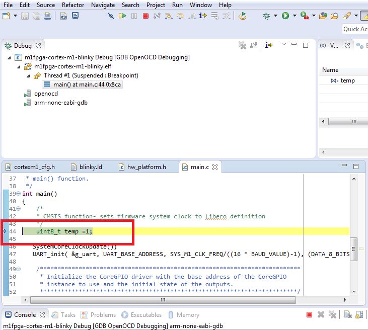
Building a Cortex-M1 Processor Subsystem

2             Building a Cortex-M1 Processor Subsystem

              Microsemi PolarFire® FPGAs support Cortex-M1 soft processors that can be used to run user
              applications. This tutorial explains how to build a Cortex-M1 processor subsystem using the Libero® SoC
              design suite. It lists the IP cores required to design a Cortex-M1 processor subsystem, describes how to
              configure and connect them and walks you through the Libero design flow to complete building it.
              This tutorial also shows how to run the user application in release and debug mode on a PolarFire
              Evaluation Kit board. The application prints the string, Hello World! on the serial terminal, and blinks
              the LEDs on the board.

2.1           Requirements
              The following table lists the hardware and software requirements for building the Cortex-M1 processor
              subsystem.

 Table 1 •      Tutorial Requirements

  Hardware
  Host PC                                                      Windows 7, 8.1, or 10
  PolarFire Evaluation Kit (MPF300TS-EVAL-KIT)                 Rev D or later
  —12 V, 5 A AC power adapter and cord
  — USB 2.0 A to Mini-B cable for UART and
  programming
  Software
  Libero SoC design suite
                                                                      Note: Refer to the readme.txt file provided in the
  Firmware Catalog1
                                                                            design files for the software versions used
  SoftConsole                                                               with this reference design.
  Serial Terminal Emulation Program                            Putty or HyperTerminal
                                                               www.putty.org

 1.   Firmware catalog is included in the installation package of Libero SoC.

      Note: Libero SmartDesign and configuration screen shots shown in this guide are for illustration purpose only.
            Open the Libero design to see the latest updates.

                                        Microsemi Proprietary TU0778 Revision 7.0                                          2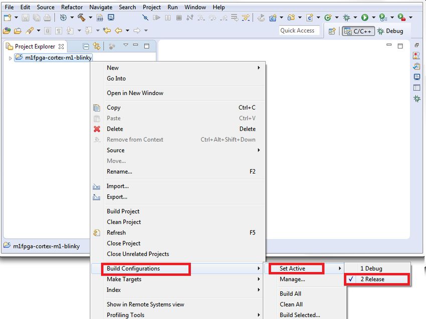
Building a Cortex-M1 Processor Subsystem

2.2          Prerequisites
             Before you begin building a Cortex-M1 subsystem, all of the required components must be downloaded
             and installed as follows:
             1.   For demo design files download link:
                  http://soc.microsemi.com/download/rsc/?f=mpf_tu0778_df
             2.   Download and install SoftConsole (as indicated in the website for this design) on the host PC from
                  the following location:
                  https://www.microsemi.com/products/fpga-soc/design-resources/design-software/softcon-
                  sole#downloads
             3.   Download and install Libero SoC (as indicated in the website for this design) on the host PC from the
                  following location:
                  https://www.microsemi.com/product-directory/design-resources/1750-libero-soc#downloads
             4.   Start the Libero design suite application and download the latest versions of the following IP cores
                  from Catalog:
                  •    CoreAHBtoAPB3: Bridge between the AHB and the APB domains.
                  •    CoreUARTapb: Controller for UART communication between the device and the host PC.
                  •    PF_SRAM_AHBL_AXI: Main memory of the Cortex-M1 soft processor.
                  •    CoreGPIO: Interface to enable the onboard LEDs.
                  •    CoreAHBLite: Bus interconnect for the AHB domain.
                  •    CoreAPB3: Bus to interface with the APB peripherals.
                  •    PF_INIT_MONITOR: Initialization monitoring resource to assert the device’s initialization.
                  •    PF_CCC: Clocking resource driving clocks to all the blocks in the design.
                  •    CORERESET_PF: Used to provide an asynchronous reset to all blocks in the design.
             5.   To download the licensed CORECORTEXM1 IP core:
                  •    Fill the Cortex-M1 agreement form available on the https://www.microsemi.com/form/91-coreip-
                       cortex-m1 webpage.
                  •    Submit the form.
             An email with the Cortex-M1 ZIP file is sent. Extract the ZIP file and import Cortex-M1.CPZ into the
             vault using the Add Core to Vault option as shown in the following figure.
Figure 1 •   Add Core to Vault

             You can now start building the Cortex-M1 processor subsystem in the Libero SoC.

2.3          Creating a Cortex-M1 Processor Subsystem
             Creating a Cortex-M1 processor subsystem involves:
             •    Creating a Libero SoC Project, page 4
             •    Creating a New SmartDesign Component, page 7
             •    Instantiating the IP Cores in SmartDesign, page 7
             •    Connecting IP Blocks in SmartDesign, page 15
             •    Generating SmartDesign Component, page 17
             •    Managing Timing Constraints, page 18
             •    Running Libero Design Flow, page 18
             The tutorial describes how to create an ARM Cortex-M1 subsystem for executing user applications. The
             user application can be stored in the sNVM, uPROM or SPI Flash. In this tutorial, the user application is
             stored in sNVM. At device power-up, the PolarFire System Controller initializes the designated LSRAMs
             with the user application from sNVM and releases the system reset. The Cortex-M1 soft processor exits
             the reset and starts executing the application. The user application prints the UART message “Hello
             World!” and blinks LEDs.

                                     Microsemi Proprietary TU0778 Revision 7.0                                         3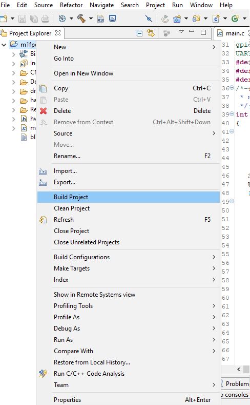
Building a Cortex-M1 Processor Subsystem

             During the Libero design flow, the required non-volatile memory (sNVM, uPROM, or SPI Flash) must be
             specified for the fabric RAMs initialization. Then, the Fabric RAM initialization client must be created. The
             created fabric RAMs initialization client is stored in the sNVM, uPROM, or SPI Flash according to the
             user selection.
             The following figure shows the top-level block diagram of the design.
Figure 2 •   Block Diagram

                                               PolarFire FPGA

         Fabric                                                                            sNVM or
                                                                                           uPROM

                                                                                                        SC_SPI
                                                                             Initialized    System               SPI
                                                                  LSRAM     at power-up                          Flash
                                                                                           Controller
                  ARM Cortex-M1 Processor

                                                                   UART                                          PuTTY

                                                                   GPIO                                          LEDs

             This section describes how to perform all the procedures required to create a Cortex-M1 processor
             subsystem in a new SmartDesign canvas.

2.3.1        Creating a Libero SoC Project
             To create a Libero SoC project, perform the following steps:
             1.    From the Libero SoC Menu bar, click Project > New Project.
             2.    Enter the following New Project information as shown in the following figure and click Next.
                   •   Project name: PolarFire_CortexM1_Subsystem
                   •   Project location: Select an appropriate location (for example,
                       F:/Microsemi/CortexM1_Project)
                   •   Preferred HDL type: Verilog

                                      Microsemi Proprietary TU0778 Revision 7.0                                          4
Building a Cortex-M1 Processor Subsystem
Figure 3 • New Project Details
3. Select the following values using the drop-down list for Device Selection as shown in the following
figure and click Next.
• Family: PolarFire
• Die: MPF300T
• Package: FCG1152
• Speed: STD
• Range: EXT
• Part Number: MPF300T-1FCG1152E
Figure 4 • Device Selection
Microsemi Proprietary TU0778 Revision 7.0 5Building a Cortex-M1 Processor Subsystem
4. To retain the default Core Voltage and I/O settings, click Next in the Device Settings window.
Figure 5 • Device Settings
5. In the Add HDL Sources window, click Next to go to the next step because HDL files are unused.
6. In the Add constraints window, click Import file to import the I/O constraint file as shown in the
following figure.
Figure 6 • Add Constraints Window
7. In the Import files window, locate the user_io.pdc file in the
DesignFiles_directory\Source folder, and double-click it.
8. Click Finish.
The following message displayed in the Log pane:
The PolarFire_CortexM1_Subsystem project was created.
The Reports tab is highlighted and the project details are printed to the PolarFire_CortexM1_-
Subsystem.log file.
The Libero SoC project for PolarFire Cortex-M1 design is successfully created.
Microsemi Proprietary TU0778 Revision 7.0 6Building a Cortex-M1 Processor Subsystem
2.3.2 Creating a New SmartDesign Component
To create a new SmartDesign component, perform the following steps:
1. Select File > New > SmartDesign.
2. In the Create New SmartDesign dialog box, enter CortexM1_Subsystem as the name of the new
SmartDesign project, as shown in the following figure.
3. Click OK.
Figure 7 • Create New SmartDesign
The CortexM1_Subsystem SmartDesign tab opens. The CortexM1_Subsystem SmartDesign component
is successfully created. Next, we need to instantiate, configure, and connect the IP Cores required to
build the processor subsystem.
2.3.3 Instantiating the IP Cores in SmartDesign
After an IP core is dragged into SmartDesign, Libero displays the Create Component window. A
component name for the IP core must be entered in this window. After naming the component, the
configurator of that IP core is displayed and after configuring the IP core, Libero generates the design
component of that IP core and instantiates it in SmartDesign. HDL files can be dragged into SmartDesign
and instantiated directly. For the recent version of IP Cores, refer Table 1, page 2.
2.3.3.1 Instantiating CORERESET_PF
Note: The version used in this design is 2.1.100.
To instantiate and configure COREREST_PF:
1. From the Catalog, find and drag CORERESET_PF IP into SmartDesign.
2. In the Create Component window, enter pf_reset as the component name.
3. In the CoreReset_PF configurator, retain the default configuration and click OK.
4. The CoreReset_PF IP is successfully instantiated in SmartDesign.
2.3.3.2 Instantiating PF_INIT_MONITOR
To instantiate PF_INIT_MONITOR, perform the following steps:
1. From the Catalog, find and drag the PolarFire Initialization Monitor IP core into SmartDesign.
2. In the Create Component window, enter PF_INIT_MONITOR_0 as the Component name and click
OK.
3. In the PF_INIT_MONITOR Configurator, Uncheck Enable Bank0, Enable Bank1, Enable Bank2,
and Enable Bank4 calibration status pins as shown in Figure 8, page 8 and click OK.
The PF_INIT_MONITOR IP component is successfully instantiated and generated.
Microsemi Proprietary TU0778 Revision 7.0 7Building a Cortex-M1 Processor Subsystem
Figure 8 • Instantiating PF_INIT_MONITOR
2.3.3.3 Instantiating PF_CCC
To instantiate PF_CCC, perform the following steps:
1. From the Catalog, find and drag the PF_CCC IP core into SmartDesign.
2. In the Create Component window, enter PF_CCC_0 as the Component name and click OK.
3. In the PF_CCC Configurator:
• Retain the configuration to PLL-Single.
• In the Clock Options PLL tab (Figure 9, page 9), set the Input Frequency to 50 MHz and
Bandwidth to High.
• Set the Power/Jitter to Maximize VCO for Lowest Jitter.
• Set the Feedback Mode to Post-VCO.
• In the Output Clocks tab > Output Clock 0 pane (Figure 10, page 9), ensure that the Enabled
checkbox is selected.
• Requested Frequency is set to 80 MHz. Ensure that the Global Clock checkbox is selected.
• Click OK.
Microsemi Proprietary TU0778 Revision 7.0 8Building a Cortex-M1 Processor Subsystem
Figure 9 • PF_CCC Clock Options
Figure 10 • PF_CCC Output Clocks
There is a possibility of a warning message to check the log window. Click OK to proceed further.
The PF_CCC IP component is successfully instantiated and generated.
Microsemi Proprietary TU0778 Revision 7.0 9Building a Cortex-M1 Processor Subsystem
2.3.3.4 Instantiating CoreCORTEXM1
To instantiate CoreCORTEXM1, perform the following steps:
1. From the Catalog, find and drag the CoreCORTEXM1 into SmartDesign.
2. In the Create Component dialog box, enter CoretxM1_0 as the component name and click OK.
3. In the CoreCORTEXM1 Configurator, set the Debug Interface to FlashPro and ensure that the
Include reset control logic check box is selected, as shown in the following figure.
4. Click OK.
Figure 11 • CoreCORTEXM1 Configurator
The CoreCORTEXM1 IP component is successfully instantiated and generated.
Microsemi Proprietary TU0778 Revision 7.0 10Building a Cortex-M1 Processor Subsystem
2.3.3.5 Instantiating CoreAHBLite
To instantiate CoreAHBLite, perform the following steps:
1. From the Catalog, find and drag the CoreAHBLite IP core into SmartDesign.
2. In the Create Component window, enter coreabhlite_0 as the component name and click OK.
3. In the CoreAHBLite Configurator, do the following settings as shown in the following figure:
• Set the Memory space to 1 MB addressable space apportioned into 16 slave slots, each of
size 64 KB.
• From the Enable Master Access pane select only the M0 can access slot 0 and M0 can
access slot 4.
• Click OK.
Figure 12 • CoreAHBLite Configurator
The CoreAHBLite IP component is successfully instantiated and generated.
2.3.3.6 Instantiating PF_SRAM_AHBL_AXI
To instantiate PF_SRAM_AHBL_AXI, perform the following steps:
1. From the Catalog, find and drag the PF_SRAM_AHBL_AXI IP core into SmartDesign.
2. In the Create Component window, enter PF_SRAM as the component name and click OK.
3. In the PF_SRAM_AHBL_AXI Configurator, do the following settings as shown in Figure 13,
page 12:
• Set the SRAM type to LSRAM.
• Set the Memory Depth to 16384 to create 64 KB (16384 × 4 bytes) memory.
• Set the Fabric Interface type to AHBLite.
• Click Finish.
Microsemi Proprietary TU0778 Revision 7.0 11Building a Cortex-M1 Processor Subsystem
Figure 13 • PF_SRAM_AHBL_AXI Configurator
The PF_SRAM_AHBL_AXI IP component is successfully instantiated and generated.
2.3.3.7 Instantiating CoreAHBtoAPB3
To instantiate CoreAHBtoAPB3, perform the following steps:
1. From the Catalog, find and drag the CoreAHBtoAPB3 IP core into SmartDesign.
2. In the Create Component window, enter core_ahb_to_apb3 as the component name and click
OK.
3. In the Configurator, retain the default configuration settings and click OK.
The COREAHBTOAPB3 IP component is successfully instantiated and generated.
2.3.3.8 Instantiating CoreAPB3
To instantiate CoreAPB3, perform the following steps:
1. From the Catalog, find and drag the CoreAPB3 IP core into SmartDesign.
2. In the Create Component window, enter CoreAPB3_0 as the component name and click OK.
3. In the CoreAPB3 Configurator:
• Select the Data Width Configuration pane.
• In the Data Width Configuration pane, retain the APB Master Data Bus Width value as
32-bit.
• In the Address Configuration pane, set Number of address bits driven by master to 16.
• Set Position in slave address of upper 4 bits of master address to [27:24]
(This value is not entered if master address width >= 32 bits).
• In the Enabled APB Slave Slots pane, select Slot 0 and Slot 1. Clear all the other slots.
• Click OK.
Microsemi Proprietary TU0778 Revision 7.0 12Building a Cortex-M1 Processor Subsystem
Figure 14 • CoreAPB3 Configurator
2.3.3.9 Instantiating CoreGPIO
To instantiate CoreGPIO, perform the following steps:
1. From the Catalog, find and drag the CoreGPIO IP core into SmartDesign.
2. In the Create Component window, enter CoreGPIO_0 as the component name and click OK.
3. In the CoreGPIO Configurator:
• Select the Global Configuration pane.
• In the Global Configuration pane, set APB Data Width to 32 and Output enable to Internal.
• Set Number of I/Os to 4.
• Set Single-bit interrupt port to Disabled.
• In the I/O bit 0, I/O bit 1, I/O bit 2, and I/O bit 3 panes, select Fixed Config.
• Set I/O Type to Output.
• Set the Interrupt Type to Disabled.
• Click OK.
Microsemi Proprietary TU0778 Revision 7.0 13Building a Cortex-M1 Processor Subsystem
Figure 15 • Core GPIO Configurator
The CoreGPIO IP component is successfully instantiated and generated.
2.3.3.10 Instantiating CoreUARTapb
To instantiate CoreUARTapb, perform the following steps:
1. From the Catalog, find and drag the CoreUARTapb IP core into SmartDesign.
2. In the Create Component window, enter CoreUARTapb_0 as the component name and click OK.
3. In the CoreUARTapb Configurator, retain the default configuration settings and click OK.
The CoreUARTapb IP component is successfully instantiated and generated.
The following figure shows the CortexM1_Subsystem in SmartDesign after instantiating and configuring
the IP blocks.
Figure 16 • CortexM1_Subsystem Without Connections
Microsemi Proprietary TU0778 Revision 7.0 14Building a Cortex-M1 Processor Subsystem
2.3.4 Connecting IP Blocks in SmartDesign
Connect IP blocks in CortexM1_Subsystem using any of the following connection methods:
• Using the Connection Mode option: In this method, change the SmartDesign to Connection Mode
by clicking Connection Mode on the SmartDesign window, as shown in the following figure. The
cursor changes from the normal arrow shape to the connection mode icon shape. To make a
connection in this mode, click on the first pin and drag-drop to the second pin that you want to
connect.
Figure 17 • Connection Method
• The other method is by selecting the pins to be connected together and selecting Connect from the
context menu. To select multiple pins to be connected together, press down the Ctrl key while
selecting the pins. Right-click the input source signal and select Connect to connect all the signals
together. Similarly, select the input source signal, right-click it, and select Disconnect to disconnect
the already connected signals.
Using any of the preceding methods, make the following connections:
1. Perform the following pin settings on PF_INIT_MONITOR_0:
• Select FABRIC_POR_N, PCIE_INIT_DONE, USRAM_INIT_DONE, SRAM_INIT_DONE,
XCVR_INIT_DONE, USRAM_INIT_FROM_SNVM_DONE,
USRAM_INIT_FROM_UPROM_DONE, USRAM_INIT_FROM_SPI_DONE,
SRAM_INIT_FROM_SNVM_DONE, SRAM_INIT_FROM_UPROM_DONE,
SRAM_INIT_FROM_SPI_DONE, AUTOCALIB_DONE, and right-click all of these pins and
select Mark Unused.
• Connect the DEVICE_INIT_DONE pin to pf_reset: INIT_DONE pin.
2. Perform the following pin settings on pf_reset:
• Right-click EXT_RST_N, select Promote to Top Level, and then rename it to RESETN.
• Connect FABRIC_RESET_N to CoretxM1_0: SYSRESETN, DBGRESETN, and NRESET pins.
• Right-click SS_BUSY and FF_US_RESTORE and select Tie Low.
3. Perform the following pin settings on PF_CCC_0:
• Right-click the REF_CLK_0 pin and select Promote to Top Level.
• Connect the PLL_LOCK_0 pin to pf_reset: PLL_LOCK.
• Connect OUT0_FABCLK_0 pin to the following listed pins:
• pf_reset: CLK
• CoretxM1_0: HCLK
• PF_SRAM: HCLK
• core_ahb_to_apb3: HCLK
• coreahblite_0: HCLK
• CoreUARTapb_0: PCLK
• CoreGPIO_0: PCLK
4. Perform the following pin settings on CoretxM1_0:
• Right-click WDOGRES, NMI, EDBGRQ, DBGRESTART, IRQ0, and IRQ1 to 31 pins and select Tie
Low.
• Select the SWCLKTCK, NTRST, SWDITMS, TDI, and TDO pins. Right-click and select Promote to
Top Level.
• Connect the AHB_MASTER pin to coreahblite_0: AHBmmaster0 (mirroredMaster).
• Right-click the TDO pin and select Promote to Top Level.
• Right-click WDOGRESN, LOCKUP, HALTED,SYSRESETREQ, JTAGTOP, JTAGNSW,
DBGRESTARTED and select Mark Unused.
Microsemi Proprietary TU0778 Revision 7.0 15Building a Cortex-M1 Processor Subsystem
• Connect the HRESETN pin as shown in the following list:
• coreahblite_0: HRESETN
• PF_SRAM: HRESETN
• core_ahb_to_apb3: HRESETN
• CoreUARTapb_0: PRESETN
• CoreGPIO_0: PRESETN
5. Connect coreahblite_0: AHBmslave0 (mirroredSlave) to PF_SRAM: AHBSlaveInterface.
6. Connect coreahblite_0: AHBmslave4 (mirroredSlave) to core_ahb_to_apb3: AHBSlave.
7. Connect core_ahb_to_apb3: APBmaster to APB3_0: APB3master (mirroredMaster).
8. Right-click the REMAP_M0 and select Tie Low.
9. Connect CoreAPB3_0: APBmslave0 to CoreGPIO_0: APB_bif and CoreAPB3_0: APBmslave1 to
CoreUARTapb_0: APB_bif
10. Perform the following pin settings on CoreUARTapb_0:
• Right-click the RX Pin and select Promote to Top Level.
• Right-click TXRDY, RXRDY, PARITY_ERR, OVERFLOW, and FRAMING_ERR pins and select
Mark Unused.
• Right-click the TX pin and select Promote to Top Level.
11. Perform the following pin settings on CoreGPIO_0:
• Right-click the GPIO_IN [3:0] pin and select Tie Low.
• Right-click the INT [3:0] pin and select Mark Unused.
• Right-click the GPIO_OUT [3:0] pin and select Promote to Top Level.
12. Click File > Save CortexM1_Subsystem.
The IP blocks are successfully connected.
The following figure shows the CortexM1_Subsystem in SmartDesign after connecting all IP blocks.
Figure 18 • CortexM1_Subsystem With Connections
The Cortex-M1 processor subsystem is successfully designed in SmartDesign. The system address map
can be viewed by right-clicking the SmartDesign canvas and selecting the Modify Memory Map option.
The Modify Memory Map dialog box is shown in the following figure and Figure 20, page 17 for APB3
and AHBLite peripherals.
Microsemi Proprietary TU0778 Revision 7.0 16Building a Cortex-M1 Processor Subsystem
Figure 19 • Modify Memory Map Dialog Box- APB3
Figure 20 • Modify Memory Map Dialog Box- CoreAHBLite
Now generate the SmartDesign component and run the Libero design flow.
2.3.5 Generating SmartDesign Component
To generate the component, perform the following steps:
1. In Design Hierarchy, click the Build Hierarchy option as shown in the following figure.
Figure 21 • Build Hierarchy option
2. Save the project.
3. Click Generate Component button on the SmartDesign toolbar. The following figure shows the
Generate Component button.
Microsemi Proprietary TU0778 Revision 7.0 17Building a Cortex-M1 Processor Subsystem
Figure 22 • Generate Component
After successfully generating the Cortex-M1 component, the Message dialog box displays the following
message: “The CortexM1_Subsystem was generated successfully”.
2.3.6 Managing Timing Constraints
Before running the Libero design flow, derive timing constraints as explained in the following sections.
2.3.6.1 Deriving Constraints
Derive the timing constraints using the Derived Constraints option available in the Timing tab of the
Manage Constraints window.
To derive constraints, perform the following steps:
1. Double-click Manage Constraints in the Design Flow window.
2. In the Manage Constraints window, select the Timing tab, and click Derive Constraints.
• The design hierarchy is built again. In the Message alert box, click Yes to attach the derived
constraints SDC file to the Synthesis, Place and Route, and Timing Verification.
3. The CortexM1_Subsystem_derived_contraints.sdc file is generated in the project folder.
Click Yes in the alert box to associate the derived constraint SDC file to the Synthesis, Place and
Route, and Timing Verification tools as shown in the following figure.
Figure 23 • Derived Constraints
The derived constraints SDC file is generated successfully. After including the timing constraint files,
the design flow described in the following sections must be executed to build Cortex-M1 processor
subsystem on the PolarFire device.
2.3.7 Running Libero Design Flow
The Libero design flow involves running the following processes:
• Synthesis, page 19
• Place and Route, page 19
• Verify Timing, page 20
• Generate FPGA Array Data, page 20
• Configure Design Initialization Data and Memories, page 21
• Generate Bitstream, page 24
• Run Program Action, page 25
Microsemi Proprietary TU0778 Revision 7.0 18Building a Cortex-M1 Processor Subsystem
2.3.7.1 Synthesis
To synthesize the design, perform the following steps:
1. Double-click Synthesis from the Design Flow window to synthesize the design component.
A green tick mark is displayed after the successful completion of the synthesis process as shown in
the following figure.
Figure 24 • Synthesis Completion
2. On the Reports window, see the Synthesis report and log files.
2.3.7.2 Place and Route
The Place and Route process requires I/O. The I/O constraints file user_io.pdc was imported while
creating the libero project. The user_io.pdc file must be mapped. This file is available in the design
files folder at DesignFiles_Directory\Source folder.
To map the I/O constraints, perform the following steps:
1. Double-click Manage Constraints from the Design Flow window as shown in the following figure.
Figure 25 • Manage Constraints
2. In the Manage Constraints window, select the I/O Attributes tab and select the check box next to
the user_io.pdc file as shown in the following figure.
Figure 26 • I/O Attributes
3. Save the project.
The I/O constraint file is successfully mapped. Now, double-click Place and Route from the Design
Flow window.
A green tick mark is displayed after the successful completion of the Place and Route process, as shown
in the following figure.
Microsemi Proprietary TU0778 Revision 7.0 19Building a Cortex-M1 Processor Subsystem
Figure 27 • Place and Route Completion
In the Reports window, see the Place and Route report and log files.
2.3.7.3 Verify Timing
To verify timing, perform the following steps:
1. On the Design Flow window, double-click Verify Timing.
A green tick mark is displayed after the successful completion of the verify timing process as shown
in the following figure.
Figure 28 • Verify Timing Completion
2. On the Reports window, see the Verify Timing report and log files.
2.3.7.4 Generate FPGA Array Data
To generate FPGA array data, perform the following step:
On the Design Flow window, double-click Generate FPGA Array Data.
A green tick mark is displayed after the successful generation of the FPGA array data as shown in the
following figure.
Figure 29 • FPGA Array Data Generated
Microsemi Proprietary TU0778 Revision 7.0 20Building a Cortex-M1 Processor Subsystem
2.3.7.5 Configure Design Initialization Data and Memories
This process requires the user application executable file (hex file) as input to initialize the LSRAM blocks
after device power-up. The hex file is provided along with the design files. For more information about
building the user application, see Creating User Application Using SoftConsole, page 29.
The hex file (m1fpga-cortex-m1-blinky.hex) is available in the
DesignFiles_Directory\Source folder. When the hex file is imported, a memory initialization client
is generated for LSRAM blocks. If the SoftConsole project is regenerated, ensure to delete the first line in
the .hex file. The type of .hex file used here is Release Mode Generated .hex file. The first line is deleted
in the .hex file provided with the design files.
Note: To make the .hex file generated by SoftConsole compatible with the process of configuring design
initialization data and memories in Libero, delete the extended linear record present in the first line of the
.hex file. The .hex file available in the DesignFiles_Directory\Source folder is already modified to be
compatible.
To create the memory initialization client, perform the following steps:
1. On the Design Flow window, double-click Configure Design Initialization Data and Memories.
The Design and Memory Initialization window opens as shown in the following figure.
Figure 30 • Design and Memory Initialization
2. Select the Fabric RAMs tab and select the CortexM1_Subsystem/PF_SRAM client from the list
and click Edit as shown in the following figure.
Microsemi Proprietary TU0778 Revision 7.0 21Building a Cortex-M1 Processor Subsystem
Figure 31 • Fabric RAMs Tab
3. In the Edit Fabric RAM Initialization Client dialog box, select the Content from file option, locate
the m1fpga-cortex-m1-blinky.hex file from DesignFiles_directory\Source folder
and Click OK as shown in the following figure.
Figure 32 • Edit Fabric RAM Initialization Client Dialog Box
4. Click Apply as shown in the following figure.
Figure 33 • Fabric RAM Content Applied
Microsemi Proprietary TU0778 Revision 7.0 22Building a Cortex-M1 Processor Subsystem
5. Select the Design Initialization tab and configure the following option, Memory type for third
stage initialization client: sNVM, as shown in following figure.
Figure 34 • Generate Initialization Clients
6. Double-click Generate Design Initialization Data option in the Libero design flow to generate the
initialization clients in sNVM memory.
7. When the initialization clients are generated, the status is displayed in the Log window as shown in
the following figure.
Figure 35 • Generate Design Initialization Data Status
Microsemi Proprietary TU0778 Revision 7.0 23Building a Cortex-M1 Processor Subsystem
8. Select the sNVM tab to verify that the SNVM client is generated as shown in Figure 36, page 24.
The INIT_STAGE_2_3_SNVM_CLIENT indicates that the sNVM client was successfully generated.
Figure 36 • sNVM Client Verification
The process of configuring design initialization data and memories is successfully completed.
2.3.7.6 Generate Bitstream
To generate bitstream, perform the following step:
On the Design Flow window, double-click Generate Bitstream.
A green tick mark is displayed after the successful generation of the bitstream as shown in the following
figure.
Figure 37 • Generate Bitstream Completion
On the Reports window, see the corresponding log files.
Microsemi Proprietary TU0778 Revision 7.0 24Building a Cortex-M1 Processor Subsystem
2.3.7.7 Run Program Action
After generating the bitstream, set up the PolarFire Evaluation Kit board so that the device is ready to be
programmed. Also, set up the serial terminal emulation program (PuTTY) to observe the output of the
user application.
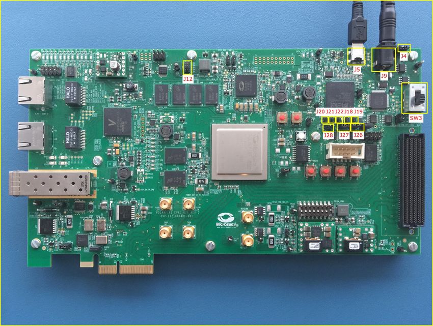
Figure 38 • Board Setup
2.3.7.7.1 Board Setup
To set up the board, perform the following steps:
1. Ensure that the jumper settings on the board are same as listed in the following table.
Table 2 • Jumper Settings
Jumper Description
J18, J19, J20, J21, and J22 Close pin 2 and 3 for programming the PolarFire FPGA through FTDI
J28 Close pin 1and 2 for programming through the on-board FlashPro5
J4 Close pin 1 and 2 for manual power switching using SW3
J12 Close pin 3 and 4 for 2.5 V
2. Connect the power supply cable to the J9 connector on the board.
3. Connect the USB cable from the Host PC to the J5 (FTDI port) on the board.
4. Power on the board using the SW3 slide switch.
The board is successfully set up.
Microsemi Proprietary TU0778 Revision 7.0 25Building a Cortex-M1 Processor Subsystem
2.3.7.7.2 Serial Terminal Emulation Program (PuTTY) Setup
The user application prints the string, “Hello World!” on the serial terminal through the UART
interface.
To setup the serial terminal program, perform the following steps:
1. Ensure that the USB cable is connected from the host PC to the J5 (USB) port on the PolarFire
Evaluation Kit board.
2. Start the PuTTY program.
3. Start Device Manager, note the second highest COM Port number and use that in the PuTTY
configuration. For example, COM Port 93 is used in this instance as shown in the following figure.
COM Port numbers may vary.
Figure 39 • COM Port Number
4. Select Serial as the Connection type as shown in the following figure.
Figure 40 • Select Serial as the Connection Type
5. Set the Serial line to connect to COM port number noted in Step 3.
6. Set the Speed (baud) to 115200 as shown in the following figure.
7. Set the Flow control to None as shown in the following figure and click Open.
Microsemi Proprietary TU0778 Revision 7.0 26Building a Cortex-M1 Processor Subsystem
Figure 41 • PuTTY Configuration
PuTTY opens successfully, and this completes the serial terminal emulation program setup.
To program the PolarFire device, double-click Run PROGRAM Action from the Libero > Design Flow
tab. A green tick mark is displayed after the successful completion of the Run Program Action process as
shown in the following figure.
Figure 42 • Run Program Action Completion
When the device is successfully programmed, the device gets reset and performs the following sequence
of operations:
Microsemi Proprietary TU0778 Revision 7.0 27Building a Cortex-M1 Processor Subsystem
1. The PolarFire System Controller initializes the LSRAM with the user application code from sNVM
and releases the system reset.
2. The CORTEX-M1 processor completes the reset and executes the user application from LSRAM.
As a result, LEDs 4, 5, 6, and 7 blink and the string, “Hello World!” is printed on the PuTTY as
shown in the following figure.
Figure 43 • Hello World In Release Mode
The Cortex-M1 processor subsystem is successfully built and programmed on the board.
Microsemi Proprietary TU0778 Revision 7.0 28Creating User Application Using SoftConsole
3 Creating User Application Using SoftConsole
This section describes how to create and debug the Cortex-M1 application using SoftConsole.
Creating the user application involves:
• Creating a Cortex-M1 Project, page 29
• Downloading the Firmware Drivers, page 31
• Importing the Firmware Drivers, page 33
• Creating the main.c File, page 34
• Configuring the Cortex-M1 Project, page 35
• Mapping Memory and Peripheral Addresses, page 40
• Setting the UART Baud Rate, page 41
• Building the User Application in Release Mode, page 42
• Building In Debug Mode and Debugging the User Application, page 44
3.1 Creating a Cortex-M1 Project
To create a Cortex-M1 project, perform the following steps:
1. Create a SoftConsole workspace folder on the host PC for storing SoftConsole projects. For
example, F:\Tutorial\CortexM1.
2. Start SoftConsole. In the Workspace Launcher dialog box, paste F:\Tutorial\CortexM1 as the
workspace location and click OK as shown in the following figure.
Figure 44 • Workspace Launcher
When the workspace is successfully launched, the metadata and the RemoteSystemsTempFiles
folders are created in the workspace directory. The SoftConsole main window opens.
3. Select File > New > Project as shown in the following figure.
Figure 45 • Creating New C Project
Microsemi Proprietary TU0778 Revision 7.0 29Creating User Application Using SoftConsole
4. In the New Project window, expand C/C++, select C Project, and then, select Next.
Figure 46 • New Project Window
5. In the Project type pane:
• Enter a name for the project in the Project name field. For example, m1fpga-cortex-m1-
blinky.
• Expand Executable and select Empty Project as shown in the following figure and then, click
Next.
Figure 47 • C Project Window
6. In the Select Configurations window, select Debug and Release, and then click Next.
7. Retain the default Toolchain name and Toolchain path, and then click Finish.
Microsemi Proprietary TU0778 Revision 7.0 30Creating User Application Using SoftConsole
An empty Cortex-M1 project (m1fpga-cortex-m1-blinky) is created in Debug and Release
mode as shown in the following figure.
Figure 48 • Empty Cortex-M1 Project
The Cortex-M1 project is successfully created.
3.2 Downloading the Firmware Drivers
The empty Cortex-M1 project requires the hardware abstraction layer (HAL) files,
Cortex microcontroller software interface standard (CMSIS) files, and the following peripheral drivers:
• CoreGPIO
• CoreUARTapb
Download the peripheral drivers using the Firmware Catalog application. This application is installed
during Libero installation. For more information on Firmware Catalog, refer Prerequisites, page 3.
To download the drivers, perform the following steps:
1. Create a folder named firmware in the CortexM1 project workspace.
2. Start Firmware Catalog. The following figure shows the Firmware Catalog window.
Figure 49 • Firmware Catalog Window
3. If new cores are available, click Download them now!
Microsemi Proprietary TU0778 Revision 7.0 31Creating User Application Using SoftConsole
4. In the Firmware Catalog window, right-click the latest CoreGPIO Driver, and select Generate.
5. In the Generate Options window, locate the folder named firmware and click OK.
Figure 50 • Generate Options
When the files are generated, the Reports window lists the files generated as shown in the following
figure.
Figure 51 • CoreGPIO Files Report
6. In the Firmware Catalog window, right-click the latest CoreUARTapb Driver and select Generate.
7. In the Generate Options window, enter F:\Tutorial\CortexM1\firmware as the
Project folder, and click OK.
When the files are generated, the Reports window lists the files generated as shown in the following
figure.
Figure 52 • CoreUARTapb Files Report
8. Copy the following folders and files from DesignFiles_Diretory\Source to
F:\Tutorial\CortexM1\firmware at the Project folder.
• CMSIS
• hal
• blinky.ld
• hw_platform.h
This completes the copying of CMSIS and HALs files requirements.
HAL files and firmware drivers are downloaded.
Microsemi Proprietary TU0778 Revision 7.0 32Creating User Application Using SoftConsole
3.3 Importing the Firmware Drivers
After downloading the drivers, CMSIS, and HAL files, import them into the empty Cortex-M1 project
created.
To import the drivers, perform the following steps:
1. In SoftConsole, right-click the m1fpga-cortex-m1-blinky project, and select Import as shown
in the following figure.
Figure 53 • Import Option
2. In the Import window, expand the General folder and double-click File System as shown in the
following figure.
Figure 54 • Import Window
3. In the continued Import window, do the following steps (see Figure 55, page 34):
• Click Browse and locate the F:\Tutorial\CortexM1\firmware folder
• Select the firmware folder and click OK.
• Expand the firmware folder and select all the checkbox as shown in the following figure.
• Click Finish.
Microsemi Proprietary TU0778 Revision 7.0 33Creating User Application Using SoftConsole
Figure 55 • Import Window Continued
The CMSIS, HAL files and peripheral drivers are successfully imported into the m1fpga-cortex-m1-
blinky project.
3.4 Creating the main.c File
To update the main.c file, perform the following steps:
1. In the Menu bar, click File and select New > Source File.
2. In the New Source File dialog box, enter main.c in the Source file field and click Finish as shown
in the following figure.
Figure 56 • Creating the main.c File
The main.c file is created inside the project as shown in the following figure.
Microsemi Proprietary TU0778 Revision 7.0 34Creating User Application Using SoftConsole
Figure 57 • The main.c file
3. Copy all of the content of the DesignFiles_directory\Source\main.c file and paste it in the
main.c file of the SoftConsole project.
4. Save the SoftConsole main.c file.
This updates the main.c file.
3.5 Configuring the Cortex-M1 Project
At this stage, the location of CMSIS, drivers and HAL files are not mapped.
To map CMSIS, drivers and HAL files, perform the following steps:
1. In the project explorer, right-click the m1fpga-cortex-m1-blinky project and select Properties.
2. Expand C/C++ Build and select Settings.
3. Set the Configuration to All Configurations as shown in the following figure.
Figure 58 • All Configuration Setting
4. In the Tool Settings, expand Target Processor, and set the ARM family to cortex-m1.
5. Retain all the other default settings, as shown in the following figure:
Microsemi Proprietary TU0778 Revision 7.0 35Creating User Application Using SoftConsole
Figure 59 • Target Processor
6. In the Tool Settings tab, expand GNU ARM CROSS C Compiler and select Includes.
7. To add driver, HAL, and CMSIS directory paths, click Add as shown in the following figure.
Figure 60 • Tool Settings Options
Microsemi Proprietary TU0778 Revision 7.0 36Creating User Application Using SoftConsole
8. In the Add directory path dialog box, click Workspace as shown in the following figure.
Figure 61 • Adding CoreGPIO Directory Path
9. In the Folder Selection dialog box, expand m1fpga-cortex-m1-blinky project > drivers and
select the CoreGPIO and CoreUARTapb folders and click OK, as shown in the following figure.
Figure 62 • Adding the CoreGPIO Folder
10. In the Add directory path dialog box, click OK.
The CoreGPIO and the CoreUARTapb folder paths are added as shown in the following figure.
Figure 63 • CoreGPIO Path Added
Microsemi Proprietary TU0778 Revision 7.0 37Creating User Application Using SoftConsole
11. Similarly, add the other paths as shown in the following figures.
Figure 64 • Adding CMSIS and startup_gcc paths
Figure 65 • Adding HAL, CortexM1, and GNU Paths
12. In GNU ARM CROSS C Compiler, select Miscellaneous and set the Other compiler flags to:
--specs=cmsis.specs (as shown in the following figure).
Figure 66 • Miscellaneous Setting
13. Click OK.
Microsemi Proprietary TU0778 Revision 7.0 38Creating User Application Using SoftConsole
The CMSIS, drivers, and HAL directory paths are successfully mapped as shown in the following fig-
ure.
Figure 67 • Mapping Successful
14. From GNU ARM CROSS C Linker > General use the Add option to map the blinky.ld linker
script.
15. In the Add file path window, click Workspace, and expand the m1fpga-cortex-m1-blinky
project and select the blinky.ld file, as shown in the following figure.
Figure 68 • Mapping Linker Script
16. Click OK.
Microsemi Proprietary TU0778 Revision 7.0 39You can also read