Regarding defrosting methods
←
→
Page content transcription
If your browser does not render page correctly, please read the page content below
E3S Web of Conferences 286, 01012 (2021)                                 https://doi.org/10.1051/e3sconf/202128601012
TE-RE-RD 2021

      Review regarding defrosting methods                                                                     for
      refrigeration and heat pump systems
      Jamal Al Douri1,3, Kamel S. Hmood1,2,Valentin Apostol1, Horatiu Pop1*, Saleh J.
      Alqaisy1,3 and Elena Beatrice Ibrean1

      1Dept. of Applied Thermodynamics, Engines, Thermal and Refrigeration Equipment, University
       POLITEHNICA of Bucharest, Romania
      2 University of BABYLON, Iraq
      3 University of TECHNOLOGY, Iraq

                    Abstract: The paper presents a literature review regarding defrosting
                    methods for household refrigeration and heat pumps. The literature review
                    covers the period between 2008 and 2020. A number of 61 papers have
                    been studied. The literature review was conducted by dividing the defrost
                    methods into passive and active. Passive methods involve surface coating
                    and off-cycle. The active defrost methods involve reverse cycle, ultrasonic
                    vibration, hot–gas defrost, electric heating and hot fluid. Surface coating
                    and ultrasonic vibration are recent defrost methods proposed in the
                    literature. Also, recently, phase change materials have been used in
                    household refrigerators to improve their efficiency. This is a topic that
                    needs further investigation and is a subject of interest as it can lead to
                    lower energy consumption during defrost cycles. From the present study,
                    the research direction regarding the use of PCMs in defrost cycles can be
                    highlighted.

      Keywords: defrost, PCM, refrigeration systems, heat pumps
      1 Introduction
      Vapour compression refrigeration systems (VCRs) are the most widely used technical
      solution in the field of artificial cooling. Frost accumulation on the evaporator surface is an
      important problem. Frost appears when the moist air comes into contact with the evaporator
      surface having a temperature lower than 0°C [1]. When frost accumulates on the evaporator
      surface, it acts as a thermal insulator leading to lower performance of the refrigeration
      system and in consequence, to higher energy consumption [2, 3]. To avoid the low
      performance of the refrigeration system, the accumulated frost needs to be removed. The
      same observations can be applied in the case of heat pumps. In this context, the present
      work presents a literature review regarding defrosting methods used in VCRs and heat
      pumps. In this work, a defrost method refers to any method that prevents frost formation
      and also to frost removal after formation.
          Section 2 of the paper presents the most widely used passive and active defrost
      methods, Section 3 shortly presents phase change materials (PCMs), Section 4 presents the
      application of PCMs in household refrigeration systems and discusses the possibility to use
      PCMs in defrosting cycles. Conclusions are presented in Section 5.
          The literature review covers the period between 2008 and 2020. A number of 61 papers
      have been studied. The literature review was conducted by dividing the defrost methods
      into passive and active. For each method, the authors have struggled to cover the available

      * Corresponding author:horatiu.pop@upb.ro

© The Authors, published by EDP Sciences. This is an open access article distributed under the terms of the Creative Commons
Attribution License 4.0 (http://creativecommons.org/licenses/by/4.0/).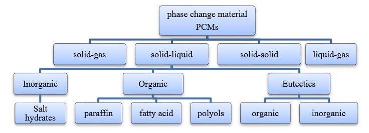
E3S Web of Conferences 286, 01012 (2021)                           https://doi.org/10.1051/e3sconf/202128601012
TE-RE-RD 2021

      scientific literature and present the conducted work in a synthetic and easy to follow
      manner.

      2 Passive and active defrosting methods
      There are two main types of defrosting methods: passive and active. In this section, each of
      the two defrosting methods will be approached and discussed.
      2.1 Passive defrosting
      A passive defrost method is a method that does not involve direct energy consumption
      during the defrost process. The most commonly used passive defrost methods are surface
      coating and off-cycle [3].
      2.1.1 Surface coating
      In recent years, with the advance of material technology, evaporator surface coating has
      become a simpler and more effective anti-frosting technology. Wang et al [4] investigated
      three types of evaporator fins namely, hydrophilic, bare and superhydrophobic, as shown in
      Fig.1. They concluded that the superhydrophobic fin outperforms the hydrophilic and bare
      fins in terms of slowing droplet condensation time. Cai et al [5] investigated frost growth
      on hydrophobic and bare surfaces. Results indicated that hydrophobic surfaces can
      delay the growth of the frost layer .

                          (a )                        (b)                           (c)
      Fig.1. Water retention on three types of fins: (a) hydrophilic, (b) bare and (c) superhydrophobic.
          Wang et al. [6] investigated the effect of the surface type on defrosting time. They
      compared the efficiency of superhydrophobic, hydrophilic and bare surfaces during
      defrosting. They concluded that in the case of superhydrophobic surfaces, the defrosting
      time and energy consumption have decreased compared to hydrophilic and bare surfaces.
       Jing et al. [7] investigated the phenomena of frosting and defrosting for a rigid
      superhydrophobic surface and a flexible superhydrophobic surface. The experiments show
      that the rigid superhydrophobic surface has the advantage of preserving its properties even
      after several cycles of frosting and defrosting while the flexible superhydrophobic surface
      did not.
      2.1.2 Off-cycle defrost method
      In off-cycle defrosting methods, the air surrounding the evaporator is used as a heat source.
      Therefore, this method can be applied for defrosting in environments where the temperature
      is higher than 1°C. When the refrigeration system needs to defrost, the compressor stops

                                                        2
E3S Web of Conferences 286, 01012 (2021) https://doi.org/10.1051/e3sconf/202128601012
TE-RE-RD 2021
and with it the cooling process. The frost formed on the evaporator starts to melt in time.
After the melting process ends, the operation of the refrigeration system is resumed. The
advantages of the off-cycle defrost method involve simplicity and low cost [3]. The main
disadvantage of the off-cycle defrost method is that it takes a lot of time because the
required heat is taken from the surrounding air [8, 9].
2.2 Active defrosting
The active defrost methods are methods that involve direct energy consumption during the
defrost process. The most widely used active defrost methods are: reverse cycle, ultrasonic
vibration, hot-gas, electric heating and hot fluid [3].
2.2.1 Reverse cycle defrosting
Reverse cycle defrosting involves a four-way valve that allows changing the refrigerant
flow path. At the moment when the defrost process is activated, the hot refrigerant coming
from the compressors flows through the evaporator (which now acts as a condenser). In the
evaporator, the refrigerant condenses and the heat released is used in the defrost process.
After the evaporator, the refrigerant flows through a liquid receiver and undergoes an
expansion process in an expansion valve before entering the condenser (which acts now as
an evaporator). Finally, the refrigerant enters the compressor and the defrost process can
continue until the frost formed on the evaporator is removed [10]. The reverse cycle defrost
method is very effective leading to a short defrost time [3]. Minglu et al. [11] made a
comparison for the defrosting system of an air source heat pump by using the thermal
energy storage method and the reverse cycle defrost method. They concluded that in the
case of the thermal energy storage method, the defrosting time shortened from 71.4 % to
80.5% and the energy consumption decreased by 65.1 % to 85.2% in comparison to the
normal reverse cycle defrosting process. Wang et al. [12] experimentally tested two
defrosting methods for a refrigeration system utilized in a cold room. The first method
was electric heater defrosting and the second was reverse cycle defrost. They concluded
that when an electric heater has been used for defrosting, the energy consumption was
reduced by 20%. At the same time, the temperature inside the cold storage has been
reduced by 7°C during the defrosting period. For the reverse cycle method, the time of
defrosting has been reduced by 19% and the energy consumption was reduced by 27.2%. In
the same operational condition, the reverse cycle defrost method saves more energy than
the electric heater method.
2.2.2 Ultrasonic vibration
Ultrasonic vibration is one of the strategies applied for preventing the growth of the frost
layer [13]. Cheng et al. studied the effect of low frequencies ranging from 100 to 200 Hz on
the frost layer and found that it had little effect on the frost layer [14]. K. Adachi et al. [15]
have studied the effect of 37 kHz high-frequency on an aluminium alloy plate in an
environment with air at around 100% relative humidity and 2°C. The authors found that
high-amplitude ultrasonic vibrations applied to an aluminium alloy plate can inhibit frost
accumulation by about 60% [15]. Tan et al. [16] investigated the effect of using ultrasonic
vibration to remove frost from a finned tube evaporator of an air source heat pump. The
authors used an ultrasound rating power of 50 W and a resonance frequency of 40 kHz. The
result showed that the consumption of energy for the defrosting process was 3.14% to
5.46% lower than without intermittent ultrasonic vibration while the heating capability
improved by 2.2 % to 9.03%. The coefficient of performance improved by 6.51 % to 15.33
%. Li et al [17] have made an experimental study regarding the influence of 20 kHz
ultrasound on frost development for a cold flat surface as shown in Fig. 2. The experiment
shows that the frozen water droplets on the surface for which ultrasound effects have been
applied became smaller and fragmented than those corresponding to the case without
3E3S Web of Conferences 286, 01012 (2021) https://doi.org/10.1051/e3sconf/202128601012
TE-RE-RD 2021
ultrasound effects. In the case of ultrasound effects, the freezing drops occupy less than 52
% in comparison to more than 65% in the case without ultrasound effect. The frost
thickness can be reduce by 75 % during tests when ultrasound effect are applied compared
to the case without ultrasound effects. Wang et al. [18] used ultrasonic vibrations to study
the effect of frost release from finned evaporators. Experiments showed that ultrasonic
vibrations cannot remove the primary ice layer from the fins, but the frost crystals and frost
branches forming on the primary ice layer can be easily eliminated. Thus the increase of the
frost layer can be suppressed.
Fig. 2. Side-view of frost formation comparison [17].
2.2.3 Hot–gas defrost method
The hot-gas defrost method involves a pipeline connecting the compressor and the
evaporator. The compressed refrigerant vapour reaches the evaporator first, then flows to
the liquid-gas separator before entering the compressor [19]. During the hot gas defrost
process, the high-pressure refrigerant enters the evaporator and warms the tube and thus,
the frost is melting [19]. The advantage of hot-gas defrost is its efficiency because the heat
comes from inside the evaporator during the defrost process [20]. The energy consumption
of the hot-gas defrost method compared to the reverse-cycle method is smaller [20]. The
disadvantage of this process is that during the defrost process the refrigerant condenses
inside the evaporator and there is a risk of liquid entering the compressor. This risk can be
removed by controlling the refrigerant flow in such a way that it can turn back to the vapour
state on the suction line, by adding a liquid-gas separator before the compressor or adding a
small evaporator before the compressor. Due to auxiliary valves, pipes and equipment the
hot-gas defrost can generate supplementary costs.
Liu et al. [21] developed a bypass cycle defrosting technology that makes use of
compressor casing thermal storage. The experimental results show that defrosting time was
reduced by 65 % to 77 %. The overall energy consumption was reduced by 89 % to 92 %
and also, the compressor noise was reduced by 18.5 %. Cho et al. [22] have studied the
performance of the on-off and hot-gas bypass defrosting methods for three evaporators of a
cabinet showcase refrigeration system. The results showed that, although it had
comparatively more compressor power compared to the on-off cycling, the hot gas
defrosting system had a better defrosting capacity and maintained a consistent storage
temperature during defrosting.
4E3S Web of Conferences 286, 01012 (2021) https://doi.org/10.1051/e3sconf/202128601012
TE-RE-RD 2021
2.2.4 Electric defrosting method
Electric defrosting methods use electric heating elements mounted in the evaporator. The
heating elements are activated during the defrost cycle. Since the heat is applied from
outside, only a portion of the heat emitted is used to remove the frost. The rest of the heat is
transferred to the air inside the refrigerated space. When the refrigeration system resumes
operation after a defrost period, this additional heat must be removed. The advantage of this
method is that it is easy to install and control. The disadvantages of this method are: it is
expensive and consumes a lot of energy [3, 8, 9].
Yoon et al. [23] focused on improving the defrosting efficiency of a household
refrigerator by using three defrost modes. The first mode controls two heaters at the same
time; the second mode controls each heater individually and the third mode uses a radiation
heater in steps. The results showed that all modes were effective in preventing a
temperature rise in the freezer and improving the defrosting efficiency. However, the best
performance was obtained by the second mode. The temperature in the refrigerator drops
from 11°C to 5°C at the time of defrosting and improves the defrosting efficiency by 15%.
Some researchers such as Melo et al. [24] used three different types of electrical heaters,
distributed, chlorine and glass. They discovered that all three types of heaters had the same
defrosting efficiency. The glass tube heater had the highest efficiency of 48 %. Zhao et al.
[25] added an extra heater of 60 W in the middle of the evaporator besides the original
bottom one having 180 W. The aim was to observe the reduction of the temperature rise in
the freezer cabinet during the defrosting process. The results showed that adding the heater
enhanced the defrost by removing frost on both the lower and upper halves of the
evaporator simultaneously. Therefore, the defrost duration was reduced by 3.3 minutes and
at the same time, the temperature inside the freezer can be reduced by 1.1 °C during the
defrost cycle. Yin et al. [26] studied a novel defrost method using air bypass circulation and
an electric heater for cold storage. The results showed that during defrosting, circulating air
was useful for enhancing the defrost speed. Compared with the traditional method (without
air bypass), the defrost time of this new method was lowered by 62.1 %, defrost energy
consumption decreased by 61.0 % and the fluctuation in storage temperature decreased by
70.1 %. Furthermore, the efficiency of defrosting raised up to 77.6 % being 2.93 times
more efficient than the traditional method.
2.2.5 Hot fluid defrost method
The hot fluid defrost method involves the use of a fluid, usually water or brine, which is
sprayed on the evaporator. The resulting mixture of water and frost is drained. During the
defrost cycle the compressor of the refrigeration system does not work. This defrost method
can be applied only if a hot fluid source is available [8, 9]. In Table 1, the advantages and
disadvantages of the most widely used defrosting methods are summarized.
Table 1.The advantages and disadvantages of defrosting methods
Defrostmethods Advantage Disadvantages
Off-cycle defrost Simple and economical [17], Not relevant in applications
low cost, no reconstruction where temperatures are below
work [19], low maintenance freezing [19]. It takes a long
costs, it is a safe method, easy time to melt the frost [20]
to control
Applies hot liquid directly to the
Hot fluid defrost Limited for application, some
accumulated frost, able to
fluid retained on the surface,
achieve fast defrost
not widely investigated or
5E3S Web of Conferences 286, 01012 (2021) https://doi.org/10.1051/e3sconf/202128601012
TE-RE-RD 2021
applied [19], not recommended
for low-temperature
applications
Efficient in terms of defrosting
Hot - gas Extremely high working
time, mostly used in industry
pressures
[19], widely used method.
Electric Easy installation [19] High energy consumption [19]
Reverse cycle Time for defrosting shorter than Consumes more energy and is
hot –gas method [19] dangerous for use in
refrigerators due to repeated
reversing of the four-way valve,
which can result in refrigerant
leakage
2.2.6 Defrosting methods using phase change materials
There are other methods of defrosting which are using phase change materials (PCMs). The
defrosting methods using PCMs are relatively new and are slowly gaining more attention
from researchers. Next, Section 3 shortly presents an overview of PCMs and Section 4
presents the application of PCMs in household refrigeration systems and discusses the
possibility to use PCMs in defrosting cycles.
3 Phase change materials
In recent years, the PCMs have attracted more interest from researchers because of:
high storage energy capacity;
low storage volume;
isothermal behaviour during the charging and discharging phases;
The PCMs have high thermal energy storage capacity and have the ability to release and
absorb a big quantity of energy at a constant temperature [27].
3.1 Classification of phase change materials
The PCMs can be classified according to the melting temperature into three groups:
Low-temperature PCMs having a melting temperature below 15 °C.
Medium temperature PCMs having a melting temperature between 15 °Cand 90 °C.
High-temperature PCMs having a melting point above 90°C.
Fig. 3 shows the most important applications of PCMs depending on the melting point.
6E3S Web of Conferences 286, 01012 (2021) https://doi.org/10.1051/e3sconf/202128601012
TE-RE-RD 2021
Fig.3.Classification PCMs according to the melting temperature
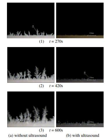
PCMs can be also classified according to the mode of phase transition: liquid-gas, solid-
liquid, solid-gas and solid-solid, as shown in Fig 4 [30].
Fig. 4. Classification PCMs according to the mode of transition
3.2 Inorganic PCMs
Inorganic PCMSs have a melting temperature ranging from 10 °C to 900°C. This type of
PCMs is widely used in solar energy applications where the required melting temperature is
high. The thermal conductivity of inorganic PCMs is higher than the organic PCMs and so
is the density. The main disadvantage of the inorganic PCMs, namely the salt hydrates, is
that they exhibit great instability as they lead to water separation during the heating process.
Most inorganic salts are not highly flammable.
Salt hydrates are the most studied type of PCM, consisting of water and salt. They have
the general formula ABnH2O and melting temperatures ranging from 15 °C to 117°C [28-
30].
The main advantages of salt hydrates are:
Low cost;
Availability;
High melting temperature;
High thermal conductivity;
High heat of fusion per unit volume;
Low volume changes;
Compatible with plastic;
The main disadvantages of salt hydrates are:
Separation means the production of additional hydrates or dehydrated salts which
tend to decrease the available active volume for heat storage.
Decrease in heat of fusion more than 73% for Na2SO4.10H2O after 1000
melt/freeze cycles.
Salt hydrates show supercooling because the freezing point of other PCMs does
not start to crystallize.
Corrosion appears in metal containers [28–30].
3.3 Organic PCMs
Organic PCMs are the most widely used type. This group of PCMs includes the paraffin
family, the fatty acids family and polyols. Among these organic PCMs, paraffin is the most
common having a melting temperature ranging from 35 °C – 70 °C. Organic PCMs can
store a large amount of energy in a small mass, are chemically and physically stable and are
compatible with a wide range of materials. At the same time, the organic PCMs are
7E3S Web of Conferences 286, 01012 (2021) https://doi.org/10.1051/e3sconf/202128601012
TE-RE-RD 2021
flammable having flashpoints close to 200°C which is a value outside their range of
application. Organic PCMs display low thermal conductivity [27-30].
Paraffin has the chemical formula CH3-(CH2)-CH3. Its main advantages are:
Large latent heat during phase change
No tendency to separate;
It is chemically stable;
When exposed to oxygen, it oxidizes slowly;
There is no change of thermal properties after frequent melting/solidification
processes;
High melting temperatures;
Non-reactive and safe;
It is compatible with all-metal containers and easy to integrate into heat storage
systems.
The disadvantages of paraffin include:
low thermal conductivity;
when changing from solid to liquid, it takes a large volume;
flammability [28].
3.4 Fatty acids
Fatty acids have the chemical formula CH3 (CH2) 2nCOOH and they have similar
properties as paraffin. The main advantage of fatty acids is their sharper phase
transformation. They are more expensive compared with paraffin and are mildly corrosive.
However, after 1500 melting/solidification cycles, the fatty acids display thermal stability
[28, 30].
3.5 Polyols
Polyols have the advantage of a small volume change. The main disadvantages involve
high phase change temperature, low latent heat and a high cost [30].
3.6 Eutectics
They consist of two or more components and have the same melting and solidification
temperature. Table 2 presents a list of PCMs and their properties. The corresponding
references are also mentioned.
Table 2.The properties and characteristics of PCMs
Ref Phase change Melting Heat of Thermal Density
materials (PCMs) Temperatur fusion conductivity [kg/m3]
e [°C] [kJ/kg] [W/(m K)]
[33] E21 21 150 0.43 1480
[34] Paraffin 26 82.7 0.2(s),0.15(l) 7870(s),750(l)
[35] CaCl2·6H2O 29.7 187.490 1.088 1710
[36] C-18 -18.40 306 0.5-0.7 1300
[37] n-octadecane 27.7 243.5 0.148 777
[38] Na2CO3.10H2O 32-36 247 - -
[39] MgCl2 .6H2O 117 168.6 0.57(l,120°C)/0.694 1450(L,120°C)/1569
(s,90°C) (s,20°C)
[39] Mg(NO3)2.6H2O 89 162.8 0.49(l,95°C)/0.611(s 1550(l.94°C)/1636(s,
,37°C) 25°C)
[39] Ba(OH)2.8H2O 48 265.7 0.653(l)/1.225(s) 1937(l)/2070(s)
[39] Polyglycol E600 22 127.2 0.189 1126(l)/1232(S)
8E3S Web of Conferences 286, 01012 (2021) https://doi.org/10.1051/e3sconf/202128601012
TE-RE-RD 2021
[39] Palmitic acid 64 185.4 0.162 850(l)/ 989(S)
[39] Capric acid 32 152.7 0.153(l) 878(l)/1004(S)
[39] Caprylic acid 16 148.5 0.149 901(l)/981(S)
[40] H20(salt 0 333 0.6(20°C)/2.2(s) 917(0°C)/998(20°C)
hydrates)
[40] KF.4H20 18.5 231 0.4 1455(18c)/1447(20°C
)
[40] Na2S04.10H20 32.4 254 1.93(s) 1485(s)
[40] Na2Hp04.12H2 35 281 1.7(s)/1.95 (l) 1520(s)/1442(l)
[40] Zn(N03)2.6H2 36.4 147 1.34(s)/2.26(l) 2065(14°C)
[40] Na2S203.5H20 48 201 1.46(s)/2.39(l) 1730(s)/1670(l)
[40] Ba(0H)2.8H20 78 267 1.17(s) 2180(s)
[41] Wax(p116) 49 210 0.24(s)/0.15(l) 780(l)/860(s)
[41] Calcium chloride 28 200 0.626(s)/0.45(l) 1500(l)/1680(s)
[42] IGI 1230A 54.2 278.2 0.25 (s)/0.135 (l) 880 (sol)/770 (l)
[43] Oleic acid 13 75.5 0.103(l) 871(l)
[43] Capric acid 32 153 0.153(l) 1004(s)/878(l)
[43] Lauric acid 44 178 0.147(l) 1007(s)/965(l)
[43] Palmitic acid 64 185 0.162(l) 989(s)/850(l)
[43] Stearic acid 69 202 0.172(l) 965(s)/848(l)
4 Application of PCMs in household refrigeration systems
Generally, in the case of household refrigerators, PCMs are used in order to improve their
performance. In literature, work has been conducted to improve the coefficient of
performance (COP) by using PCMs at the condenser level, evaporator level and inside the
cold storage space [31]. In this regard, Table 3 presents a part of the literature which has as
a subject the use of PCMs in household refrigerators. Table 3 covers the time period from
2008 to 2020.
Table 3. Literature regarding the use of PCMs in household refrigerators
Author Main conclusion Components Year
where PCMs
are used
Azzouz et al [44] The use of PCMs increases the energy The outer side 2008
efficiency and leads to enhanced heat transfer of the
from the evaporator evaporator
Azzouz et al [45] Adding PCMs shows a significant increase in The backside 2009
efficiency compared to a conventional of the
system evaporator
Long Cheng Adding PCMs results in a lower condensation Condenser 2011
et al [46] temperature, a higher evaporating temperature
and much larger subcooling, as well as a 12%
improvement in performance.
Khan and Afroz et al PCMs, decrease the fluctuation of the cabinet Evaporator 2014
[47] temperature.
Khan and Afroz et al The effect of PCMs in compressor on-off Evaporator 2015
[48] cycle has been studied. The authors found that
the number of compressors on-off cycles with
PCMs is 5% to 30% lower. The efficiency
increases and the temperature fluctuation
inside the cabinet decreases.
Sonnenrein et al [49] Water, paraffin or copolymer compound has Evaporator 2015
been used as PCM. The energy consumption
has been reduced and the temperature lowered
from 4°C to 0.5°C.
9E3S Web of Conferences 286, 01012 (2021) https://doi.org/10.1051/e3sconf/202128601012
TE-RE-RD 2021
Yusufoglu et al[50] PCMs have been used to reduce the Evaporator 2015
compressor on/off time, resulting in a 9.4%
energy saving
Reddy et al[51] The authors used PCMs to cover the Evaporator 2016
evaporator and the results show that the
cooling effect inside the chamber increased.
COP also increased from 3.29 to 3.5.
Long Cheng et al [52] PCMs have been used in condenser and Condenser- 2017
evaporator and the result shows electrical evaporator
consumption savings between 28 % and 32
%.
Bakhshipour et al [53] The authors point out that using PCMs PCMs Heat 2017
increases the convection procedure and exchanger after
results in a 9.58 % improvement of the COP. the condenser
Elarem et al [54] The experimental results indicate that energy Evaporator 2017
consumption decreased by 12% and the COP
increased by 8%, compared to the refrigerator
without PCMs.
Liu et al [55] The refrigerator's energy consumption, with Evaporator 2017
PCMs, decreased by 18.6 %, and the (free frost)
compressor ON-time ratio was reduced by
13.6 %.
Dandotiya and Banker The COP in the case of the PCMs-based Condenser 2017
et al [56] condenser was 28% higher and the energy
consumption was 15% lower.
Liu et al [21] The authors proposed the use of a compressor Compressor 2017
casing thermal storage using PCMs for
defrosting purposes. The results show that
defrosting time can be reduced by 65% to 77
%, energy consumption can be reduced by 89
% to 92 % and also, the compressor operating
noise level can be reduced by 18.5 %.
Liu et al [57] The authors used a heat exchanger after the After 2017
compressor for four different types of PCMs compressor
and modes of operation. As a result,
defrosting speed was increased by 50%
compared to the initial electric heating, while
defrosting electric energy consumption was
decreased by approximately 71%.
Zarajabad and The authors have used PCMs and fins. They Evaporator 2018
Ahmadi et al[58] noticed that the compressor's energy
consumption decreased by 17.4 %.
Tikudave and hole et They used the heat storage condensers Evaporator 2018
al[46] between the condenser and evaporator in the
household refrigerator. The results show: the
condensation temperature is lower, the
temperature inside the cabinet is more stable,
the on-time was improved, the COP increased
by 21.5 % and the energy efficiency increased
by 15%.
Pirvaram et al [59] The authors used two eutectic PCMs and the Condenser 2019
results show that the compressor work time
percentage was reduced from 32.7 % to 27.6
%. The energy consumption was reduced by
13% when using one PCM and by 8% by
using two PCMs.
10E3S Web of Conferences 286, 01012 (2021) https://doi.org/10.1051/e3sconf/202128601012
TE-RE-RD 2021
Maiorino et al [60] The use PCMs determined a noticeable Evaporator 2019
decrease of the temperature gradient within
the cabinet and extended the OFF time of the
compressor.
Abdolmaleki et al The energy consumption with PCMs was Evaporator 2020
[61] reduced by 8.37%.
As it can be noticed from Table 3, PCMs have attracted attention as a solution to
increase the efficiency of household refrigerators. As a remark, in the case of household
refrigerators, the efficiency can be further improved by using PCMs during the defrost
cycles. This is a topic that requires further investigation.
5 Conclusion
The paper presents a literature review regarding the defrost methods for vapour
compression refrigeration systems and heat pumps. The literature review covers the period
between 2008 and 2020. A number of 61 papers have been studied. One specialized in
refrigeration systems and heat pumps can notice that the available scientific literature
having as a topic defrost methods is scarce compared to other topics from refrigeration/heat
pump technology like new types of refrigerants or efficiency enhancement.
There are two main types of defrosting methods: passive and active. Passive methods
involve surface coating and off-cycle. The active defrost methods involve reverse cycle,
ultrasonic vibration, hot–gas defrost, electric heating and hot fluid. Among these methods,
surface coating and ultrasonic vibration are the most recent ones proposed in literature
while the other methods could be classified as well know and widely used methods.
The present work shows that defrosting methods are an important source of direct
energy consumption, except for the surface coating and off-cycle defrost. Reducing the
energy consumption during the defrost cycle will lead to the higher efficiency of the
refrigeration/heat pump system. In this regard, recently, phase change materials have been
used in household refrigerators to improve their efficiency. The number of papers regarding
this subject is constantly increasing. Related to phase change materials, the most recent
work involves their use in the defrost cycles of the refrigeration systems. This is a topic that
needs further investigation and is a subject of interest as it can lead to lower energy
consumption during defrost cycles. Defrost cycles using phase change materials could be
applied to both household and industrial refrigeration systems. In the next years, at least in
Europe, the standards regarding household refrigerator energy consumption will become
more strict. In this context and based on the present work, the research direction regarding
the use of PCMs in defrost cycles can be highlighted.
References
[1] M. Qu, L. Xia, S. Deng, Y. Jiang, Appl. Energy 91,122–129 (2012)
[2] W. Su, W. Li, X. Zhang, Energy Convers. Manag. 148, 1157–1169 (2017)
[3] M. Amer, C.C. Wang, Renew. Sustain. Energy Rev. 73, 53–74 (2017)
[4] F. Wang, C. Liang, M. Yang, X. Zhang, Exp. Therm. Fluid Sci. 61, 113–120(2015)
[5] L. Cai, R. Wang, P. Hou, X. Zhang, Energy Build. 43, 1159–1163(2011)
[6] F. Wang, C. Liang, M. Yang, X. Zhang, Appl. Therm. Eng. 113, 229–237 (2017)
[7] T. Jing, Y. Kim, S. Lee, D. Kim, J. Kim, W. Hwang, Appl. Surf. Sci. 276, 37–42
(2013)
[8] K. Nawaz, A. Elatar, B. Fricke, A Critical Literature Review of Defrost
Technologies for Heat Pumps and Refrigeration Systems, (US DEPARTMENT OF
ENERGY, 2018)
[9] M. Song, S. Deng, C. Dang, N. Mao, Z. Wang, Appl. Energy 211,1150–1170
11E3S Web of Conferences 286, 01012 (2021) https://doi.org/10.1051/e3sconf/202128601012
TE-RE-RD 2021
(2018)
[10] J. Shen, Z. Qian, Z. Xing, Y. Yu, M. Ge, Energy Procedia 160, 491–498,(2019)
[11] M. Qu, T. Li, S. Deng, Y. Fan, Z. Li, Appl. Therm. Eng. 121, 728–736 (2017)
[12] D. Wang, J. Jiang, L. Tao, Z. Kou, L. Yao, Appl. Therm. Eng. 127, 1267–1273
(2017)
[13] H. Tan, X. Zhang, L. Zhang, T. Tao, G. Xu, Appl. Therm. Eng. 153, 113–127
(2019)
[14] C.H. Cheng, C.C. Shiu, Int. J. Refrig. 26, 69–78 (2003)
[15] K. Adachi, K. Saiki, H. Sato, T. Ito, Japanese J. Appl. Physics, Part 1 Regul. Pap.
Short Notes Rev. Pap. 42, 682–685 (2003)
[16] H. Tan, G. Xu, T. Tao, X. Sun, W. Yao, Appl. Energy 158, 220–232,(2015)
[17] D. Li, Z. Chen, M. Shi, Exp. Therm. Fluid Sci. 34, 1247–1252,(2010)
[18] D. Wang, T. Tao, G. Xu, A. Luo, S. Kang, Exp. Therm. Fluid Sci. 36, 1–11(2012)
[19] N. Hoffenbecker, S.A. Klein, D.T. Reindl, Int. J. Refrig. 28, 605–615(2005)
[20] J.H. Rainwater, ASHRAE J. 51 38–51 (2009)
[21] Z. Liu, F. Zhao, L. Zhang, R. Zhang, M. Yuan, Y. Chi, Appl. Therm. Eng. 130,
1215–1223 (2018)
[22] H. Cho, Y. Kim, I. Jang, Energy 30, 1915–1930 (2005)
[23] Y. Yoon, H. Jeong, K.S. Lee, Energy Convers. Manag. 157, 511–516 (2018)
[24] C. Melo, F.T. Knabben, P. V. Pereira, Appl. Therm. Eng. 51, 239–245 (2013)
[25] R. Zhao, D. Huang, X. Peng, H. Yang, Int. J. Refrig. 99, 186–193 (2019)
[26] H.J. Yin, Z. Yang, A.Q. Chen, N. Zhang, Energy 37, 623–631 (2012)
[27] A.F. Regin, S.C. Solanki, J.S. Saini, Renew. Sustain. Energy Rev. 12, 2438–
2458(2008)
[28] S.D. Sharma, K. Sagara, Int. J. Green Energy 2, 1–56 (2005)
[29] J. Vadhera, A. Sura, G. Nandan, G. Dwivedi, Mater. Today Proc. 5, 3411–
3417(2018)
[30] S.F. Li, Z. hua Liu, X.J. Wang, Appl. Energy 255, 113667(2019)
[31] K. Du, J. Calautit, Z. Wang, Y. Wu, H. Liu, Appl. Energy 220, 242–273(2018)
[32] J. Shen, Z. Qian, Z. Xing, Y. Yu, M. Ge, Energy Procedia 160, 491–498 (2019)
[33] F. Wang, G. Maidment, J. Missenden, R. Tozer, Appl. Therm. Eng. 27, 2902–
2910(2007)
[34] V. Antony Aroul Raj, R. Velraj, Int. J. Therm. Sci. 50, 1573–1582 (2011)
[35] A.H. Mosaffa, F. Talati, H. Basirat Tabrizi, M.A. Rosen, Energy Build. 49, 356–
361 (2012)
[36] E. Oró, L. Miró, M.M. Farid, L.F. Cabeza, Int. J. Refrig. 35, 984–991 (2012)
[37] A. Ehsan, H. Singh, M. Saqlain, G. Farid, Sci.Int.(Lahore). 26, 1435–1438(2014)
[38] M. Jaafer, A. Alatabe, Int. J. Sci. Res. Sci. Eng. Technol. 4, 93–98(2018)
[39] M.M. Farid, A.M. Khudhair, S.A.K. Razack, S. Al-Hallaj, Energy Convers. Manag.
45, 1597–1615 (2004)
[40] A. Abhat, Sol. Energy 30, 313–332 (1983)
[41] H. El-Dessouky, F. Al-Juwayhel, Energy Convers. Manag. 38, 601–617 (1997)
[42] R.J. Warzoha, R.M. Weigand, A.S. Fleischer, Appl. Energy 137, 716–725(2015)
[43] H. Ge, H. Li, S. Mei, J. Liu, Renew. Sustain. Energy Rev. 2, 1331–346 (2013)
[44] K. Azzouz, D. Leducq, D. Gobin, Int. J. Refrig. 31, 892–901 (2008)
[45] K. Azzouz, D. Leducq, D. Gobin, Int. J. Refrig. 32, 1634–1644 (2009)
[46] W.L. Cheng, B.J. Mei, Y.N. Liu, Y.H. Huang, X.D. Yuan, Energy 36, 5797–5804
(2011)
[47] H.M.M. Afroz,Int. J. Recent adv. Mech. Eng. (IJMECH)3, 43–52(2014)
[48] M. Imran Hossen Khan, H.M.M. Afroz, Sci. Technol. Built Environ. 21, 462–468
(2015)
12E3S Web of Conferences 286, 01012 (2021) https://doi.org/10.1051/e3sconf/202128601012
TE-RE-RD 2021
[49] G. Sonnenrein, E. Baumhögger, A. Elsner, K. Fieback, A. Morbach, A. Paul, J.
Vrabec, Int. J. Refrig. 60, 166–173 (2015)
[50] Y. Yusufoglu, T. Apaydin, S. Yilmaz, H.O. Paksoy, Int. J. Refrig. 57, 173–
185(2015)
[51] R. Rahman, IOSR J. Mech. Civ. Eng. 10, 08–16(2013)
[52] W. long Cheng, M. Ding, X. dong Yuan, B.C. Han, Energy Convers. Manag. 132,
180–188 (2017)
[53] S. Bakhshipour, M.S. Valipour, Y. Pahamli, Int. J. Refrig. 83, 1–13 (2017)
[54] R. Elarem, S. Mellouli, E. Abhilash, A. Jemni, Appl. Therm. Eng. 125, 1320–
1333(2017)
[55] Z. Liu, D. Zhao, Q. Wang, Y. Chi, L. Zhang, Int. J. Refrig. 79,130–142 (2017)
[56] D. Dandotiya, N.D. Banker, Int. J. Air-Conditioning Refrig. 25, 1–9 (2017)
[57] Z. Liu, A. Li, Q. Wang, Y. Chi, L. Zhang, Appl. Therm. Eng. 118,256–265 (2017)
[58] O. Ghahramani Zarajabad, R. Ahmadi, Therm. Sci. Eng. Prog. 7,115–124 (2018)
[59] A. Pirvaram, S.M. Sadrameli, L. Abdolmaleki, Energy. 181, 321–330 (2019)
[60] A. Maiorino, M.G. Del Duca, A. Mota-Babiloni, A. Greco, C. Aprea, Int. J. Refrig.
100, 255–264 (2019)
[61] L. Abdolmaleki, S.M. Sadrameli, A. Pirvaram, Renew. Energy 145, 233–241
(2020)
13You can also read