Waste-to-Energy in Amine Gas Sweetening
←
→
Page content transcription
If your browser does not render page correctly, please read the page content below

Middle East
                                                           SERVICE REGION
                                                 Oil & Gas
                                                           ERI PRODUCT DIVISION
Waste-to-Energy in
Amine Gas Sweetening:
An Innovative Approach to Recovering Hydraulic
Energy from Natural Gas Processing Acid Gas
Removal Units

AUTHORS:

John Sienkiewicz
Senior Controls Engineer

Felix Winkler
Senior Mechanical Engineer

Mark Richter
Senior Electrical Engineer

June, 2014

Copyright ©2014 Energy Recovery Inc.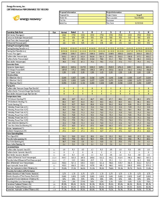
PAGE:

     1
Table of Contents

                    Executive summary                                              2

                    Introduction                                                   3

                    Conventional configuration in amine gas processing             4

                    Hydraulic turobgenerator application in amine gas processing   5

                    Process control methodology                                    8

                    Testing, validation, and deployment                            10

                    Conclusion                                                     14

                    Appendices                                                     15

                     Appendix 1: explanation of calculations used in table 3       15

                     Appendix 2: nomenclature                                      16

                      Appendix 3: subscripts                                       16

                    More Information                                               17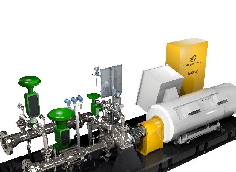
EXECUTIVE
SUMMARY
Pressure is a common byproduct of many oil and gas related operations, and though it has
the ability to reliably drive a wide range of processes, it’s largely been disregarded as a poten-
tial source of energy. This, however, is quickly changing as producers look for new and effi-
cient ways to cut carbon emissions and overcome the challenges associated with increasing

                                                                                                                       Executive Summary
operating costs. Energy Recovery’s innovative IsoGen™ system has proven to be effective to
reduce carbon footprint while creating electricity and increasing operational efficiency.

Amine gas sweetening is an energy intensive process commonly used to remove hydrogen
sulfide and carbon dioxide from natural gas streams. The process involves an amine gas con-
tactor that typically operates at pressure up to 1200 psi (83 bar), and an amine regenerator
that operates at near atmospheric pressure. Energy is first consumed in pumping lean amine
from the regenerator up to contactor pressure, and later dissipated in depressurizing the rich
amine exiting the contactor at the level control valve (LCV). The IsoGen is a skid-mounted
system with a hydraulic turbogenerator and state-of-the-art ancillary equipment. The size
of the IsoGen unit discussed in this paper is per client specifications and flow range. For this
particular reference, the IsoGen System can recover as much as 80% of the energy wasted
but the IsoGen’s efficiency can go well beyond 80% in other applications. This paper provides
an example of a hydraulic turbogenerator system retrofit for an amine gas treatment plant in
Saudi Arabia with an electrical power output at the rated operating point of 637 hp (475 kW).

                                                                                                                        PAGE:

                                                                                                                           2

           An Innovative Approach to Recovering Hydraulic Energy from Natural Gas Processing Acid Gas Removal Units.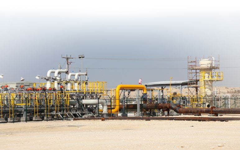
PAGE:
               INTRODUCTION
   3           Natural gas is an abundant, reliable, and clean-burning source of energy that is typically
               processed to remove impurities before use. This process, known as amine gas treating,
               gas sweetening, or acid gas removal, consumes a significant portion of the electrical en-
Introduction

               ergy associated with delivering gas from the wellhead to the distribution pipeline. Much
               of this pressure energy has historically been wasted, the value of which as a potential
               energy source has been largely ignored.

               It is now possible, however, to capture the energy found in high pressure process flows
               in the oil and gas value chain. Energy Recovery’s IsoGen™ system converts this pressure
               energy into electrical energy, creating opportunities for productivity gains and improved
               profitability. The IsoGen can be understood as a “waste-to-energy” system, analogous
               to hydroelectric power. With up to 85% efficiency, the IsoGen skids can be installed in
               parallel for maximum flexibility. This paper focuses on the core technology in the Iso-
               Gen™ system: The hydraulic turbogenerator. It explains the technology and provides wit-
               ness performance test data and results for an IsoGen™ system designed for a large gas
                                                             plant in Saudi Arabia.

                                                                                At the customer gas plant in Saudi Arabia,
                                                                                an amine circulation flow of 2500 gpm and
               The IsoGen is a                                                  a contactor to flash tank differential pres-
                                                                                sure of 475 psi result in an annual hydraulic
               waste-to-energy                                                  energy dissipation of 4.5 gigawatt-hours in
                                                                                the existing level control valve. The IsoGen™
               system much like                                                 turbogenerator to be installed in the stated
               hydroelectric power.                                             facility can capture up to 80% of this wast-
                                                                                ed energy, resulting in an annual electricity
                                                                                savings of $US 362,000, assuming an ener-
                                                                                gy cost of 0.10 USD per kilowatt-hour and
                                                                                a significant reduction in carbon footprint
                                                                                of 3,620,000 kWh x ( 1.52 lb CO2 / kWh* ),
                                                                                or 2,750 tons of CO2 per year. This reduc-
                               The IsoGen will                                  tion in carbon dioxide output translates to
                               reduce this Saudi                                almost 6,500 barrels of oil consumed or 3
                               plant’s carbon                                   million pounds of coal burned per year –
                               footprint annually                               underscoring the IsoGen’s positive envi-
                                                                                ronmental impact. Another added benefit
                               by 2,750 metric
                                                                                of the system is expanded processing ca-
                               tons of CO2.                                     pability without having to increase plant
                                                                                electrical feed size.

                          An Innovative Approach to Recovering Hydraulic Energy from Natural Gas Processing Acid Gas Removal Units.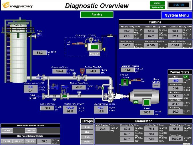
CONVENTIONAL CONFIGURATION IN
AMINE GAS PROCESSING

                                                                                                                         Conventional Configuration in Amine Gas Processing
A typical gas processing facility operates the contactor (absorber) at pressures of up to 1200 psi
and the regenerator circuit at pressures as low as 50 psi. The process is typically configured (shown
in Figure 1 below) so that a high pressure amine circulation pump pressurizes the lean amine above
the contactor pressure to start the absorption process, while a pressure letdown valve, used as the
contactor LCV, reduces pressure in the exiting amine fluid stream prior to entering the regenerator
(stripper). Energy is dissipated and lost through the letdown action of the contactor LCV.

                Figure 1 – Conventional configuration of an amine gas treating circuit

                                                                                                                                PAGE:

                                                                                                                                         4

             An Innovative Approach to Recovering Hydraulic Energy from Natural Gas Processing Acid Gas Removal Units.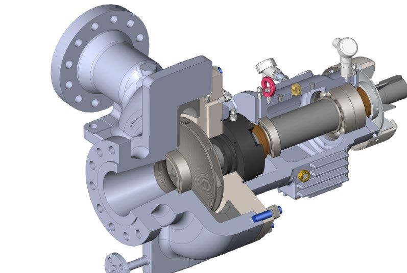
HYDRAULIC TURBOGENERATOR APPLICATION IN
                                                               AMINE GAS PROCESSING
  PAGE:

             5
Hydraulic Turobgenerator Application in Amine Gas Processing

                                                                           Figure 2 – IsoGen™ system configuration of an amine gas treating process

                                                               The IsoGen System, Figure 3 and schematically in Figure 4, is a standalone solution that coverts
                                                               hydraulic energy to electrical energy. It is designed to replace existing throttle, backpressure, and
                                                               LCVs in pipeline and process flow applications. Energy that is usually wasted within these valves
                                                               is efficiently converted to usable electricity that can be used to reduce a plant’s overall electricity
                                                               consumption or, in some cases, be returned to the electrical grid. A wide range of flows and pres-
                                                               sure drops can be accommodated at peak efficiency by a single unit using IsoGen’s unique auxiliary
                                                               nozzle technology and variable speed induction generator.

                                                                            An Innovative Approach to Recovering Hydraulic Energy from Natural Gas Processing Acid Gas Removal Units.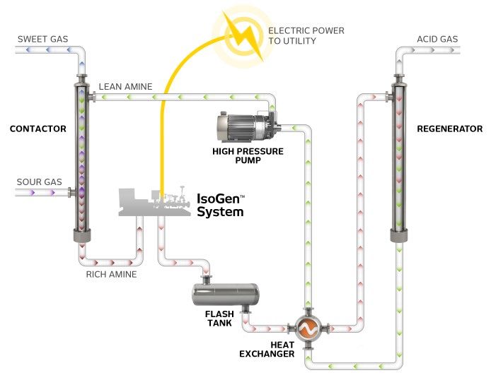
Hydraulic Turobgenerator Application

                                                                                                                                   Hydraulic Turobgenerator Application in Amine Gas Processing
    in Amine Gas Processing (cont.)
                               Electrical Power
                                   OUT to VFD
                                                                            Control
                                                                           Panel (RIO)
                                                                                                  Figure 3 – The Waste-to-Energy
                                                                                                  IsoGen™ System
                                                   Dual Gas
                               Auxilary           Seal Panel
                                Valvee

        Bypass
            ve
         Valve

         sure
     Pres
High
          e IN
     Amin
Rich                                                                                                   2-Pole Induction
                                                                                                      Generator (700hp)

           re
        ssu
     Pre
Low
             UT                                                                H
                                                                               Hydraulic
          eO
     Amin                                                                       Turbine
Rich
                                                               T
                                                               Throttle
                                                                Valve

    At the core of the IsoGen System
    is a single-stage turbine that
    drives a medium voltage variable
    speed induction generator.                                            Figure 4 – Simplified Piping and Instrumentation
                                                                          Diagram (P&ID) of the IsoGen™ System

    At the core of the IsoGen System is a single-                         replaced in a matter of hours without disturb-
    stage turbine that drives a medium voltage                            ing the process piping connections. This flex-
    variable speed induction generator. The genera-                       ibility is key to allow for plant capacity changes.
    tor’s output is conditioned to match grid volt-                       The IsoGen turbine has external oil-mist lubri-
    age and frequency at near unity power-factor                          cated anti-friction bearings that make the de-
    using a regenerative variable frequency drive                         vice highly resistant to debris suspended in the
    (VFD). Turbine runner hydraulics are custom de-                       process flow. A rigid bearing housing, low shaft
    signed and fabricated to meet each customer’s                         flexibility index (L3/D4), closed cycle oil-mist lu-
    unique process conditions. Insertable nozzle                          brication, and magnetic face seal bearing isola-               PAGE:
    and volute geometries allow the turbine hy-                           tors ensure premium reliability in even the most
    draulics to be easily retrofitted if flow or pres-                    severe operating environments. A state-of-the-
                                                                                                                                                     6
    sure drop requirements change by a significant                        art Plan 74 dual gas shaft seal allows the unit to
    amount. Because of the turbine casing’s back                          be deployed with almost any process liquid and
    pullout configuration, turbine hydraulics can be                      virtually eliminates fugitive emissions.

                  An Innovative Approach to Recovering Hydraulic Energy from Natural Gas Processing Acid Gas Removal Units.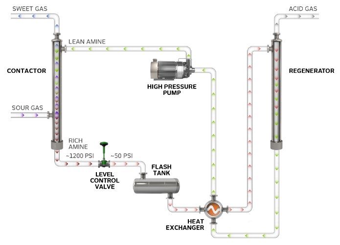
Diagnostic Overview of Hydraulic
                                                              Turbogenerator Application
  PAGE:

             7                                                Both turbine and generator are designed to be API com-
                                                              pliant and are rated for use in hazardous environments.
                                                              Pressure drops and flows that lie outside of the tur-
Diagnostic Overview of Hydraulic Turbogenerator Application

                                                              bine’s already large operating envelope are accommo-
                                                              dated using a parallel bypass valve as well as a series                            Both turbine and
                                                              throttle valve. The generator and valves are controlled                            generator are designed
                                                              by a programmable logic controller (PLC) using Energy                              to be API compliant
                                                              Recovery’s proprietary control algorithms. The PLC code                            and are rated for use in
                                                              is customized by application to seamlessly integrate                               hazardous and extreme
                                                              with existing plant controls. High operational reliability
                                                              and safety are ensured through continuous monitoring,
                                                                                                                                                 environments.
                                                              analysis, and logging of numerous process and machine
                                                              parameters. A screenshot of the PLC human machine in-
                                                              terface (HMI) can be seen in Figure 5.

                                                              Figure 5. Screen shot of the IsoGen™ system HMI at the “Normal Operating Point”

                                                                           An Innovative Approach to Recovering Hydraulic Energy from Natural Gas Processing Acid Gas Removal Units.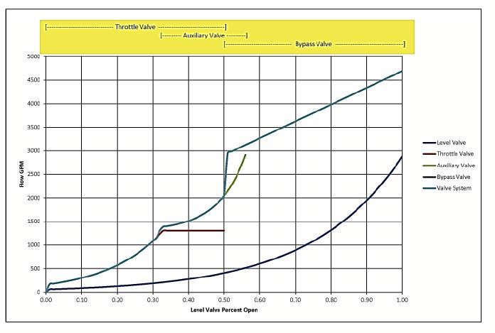
PROCESS CONTROL
METHODOLOGY
Process control of the contactor
is achieved through controlling
the flow of lean amine into the
top of the contactor and simul-
taneously controlling the level
of the rich amine in the bottom
of the contactor. The flow rate
of the amine entering the con-
tactor is controlled by a throttle
valve located downstream of
the high pressure amine circula-
tion pump. Energy Recovery rec-
ommends using VFD to control
the high pressure amine circula-
tion pump, which saves energy
by eliminating throttling losses.

The IsoGen System is designed

                                                                                                                         Process Control Methodology
to seamlessly integrate into a                                                Chart 1 – IsoGen™ valve control strategy
plant’s existing architecture by replacing the exist-
ing LCV and using the valve’s existing control sig-
nal. Contactor level control is achieved through En-
ergy Recovery’s control system, which coordinates
the operation of the auxiliary, bypass, and throttle                                     The IsoGen
valves on the IsoGen System. The level control sig-
nal is received from the plant and split into three
                                                                                         System operates
ranges to activate the three system valves.                                              at near maximum
In normal operation, the bypass valve is fully closed,
                                                                                         efficiency across
the throttle valve is fully open, and the auxiliary                                      a 21% turndown
valve performs the control function by adjusting                                         range.
the flow exiting the contactor in response to the
level control signal. The turbine in this application
achieved a flow turndown of approximately 21%
using only the auxiliary valve, while maintaining
near peak efficiency. If the level control signal de-                        The IsoGen System is
mands a flow response that is lower than the low-                            designed to seamlessly
est flow achievable in normal operation, (auxiliary
valve almost fully closed) the throttle valve begins                         integrate into a plant’s
to take over control by closing to the desired level.                        existing architecture by
If the level control signal demands a flow response
that is higher than the highest flow achievable in
                                                                             replacing the existing LCV                     PAGE:

normal operation, (auxiliary valve almost fully open)                        and using the valve’s existing                      8
the bypass valve enters the control scheme by                                control signal.
opening and bypassing additional flow to the flash
tank. Chart 1 graphically represents this behavior.

             An Innovative Approach to Recovering Hydraulic Energy from Natural Gas Processing Acid Gas Removal Units.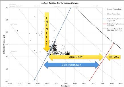
PROCESS CONTROL
PAGE:

      8
                              METHODOLOGY                                                                                               (CONT.)
Process Control Methodology

                              Chart 2 – Example of the LCV percent open command vs. the IsoGen™ system valve response

                              Chart 2 depicts the three valves’ control action                    • The bypass valve operates from 0 to 100 per
                              in response to the level control signal. The pro-                     cent open with a level control signal of 50 to
                              portions of level control signal assigned to each                     100 percent. This valve begins to open before
                              valve and the amount of overlap is implemented                        the auxiliary valve is fully open.
                              using Energy Recovery’s proprietary control al-
                              gorithms.                                                           If desired, the control algorithm can be adjusted
                                                                                                  to create operating characteristics similar to
                              • The throttle valve operates from 0 to 100 per                     the LCV the system replaces, simplifying instal-
                                cent open with a level control signal of 0 to 50                  lation. The PID controller on the plant end does
                                percent.                                                          not need to be adjusted or re-tuned when an
                                                                                                  LCV is replaced with an IsoGen™ system.
                              • The auxiliary valve operates from 0 to 100 per
                                cent open with a level control signal of 31 to
                                56 percent. This valve begins to open before
                                the throttle valve is completely open.

                                           An Innovative Approach to Recovering Hydraulic Energy from Natural Gas Processing Acid Gas Removal Units.
TESTING, VALIDATION
AND DEPLOYMENT
The IsoGen System described in this paper will be installed at a large gas plant in Saudi Arabia in
2014. Test criteria defining success and acceptable performance were extracted from industry stan-
dards, including API 610 and API 682, among others. An operating window was established based on
gas plant data representative of winter and summer process conditions.
Performance Measurement
A “normal operating point” was defined at the averaged center of the representative process data,
as well as a “rated operating point” at the upper bounds of flow and differential pressure. Eight addi-
tional test points were defined to encompass the supplied process conditions and represent a test
of the system’s operating window. A tabular representation of the test points is presented in Table 2.
The test success criteria and measured results can be summarized as follows:
Testing, Validation and Deployment
Criteria Performance Requirement Witness Test Measured Value
Normal Operating Point
Corrected** hydraulic to electrical efficiency Greater than 70% 77.3%
Power factor Greater than 0.90 0.99
Bearing housing vibration Less than 0.18 inch/s RMS 0.05, 0.07, 0.09 (X, Y, Z in/s)
Turbine bearing temperature Less than 93°C 68.5°C, 66.6°C 51.0°C (Inboard, outboard, radial)*
Rated Operating Point
Corrected** hydraulic to electrical efficiency Greater than 70% 75.7%
Power factor Greater than 0.90 0.99
Bearing housing vibration Less than 0.18 inch/s RMS 0.06, 0.08, 0.10 (X, Y, Z in/s)
Turbine bearing temperature Less than 93°C 68.7°C, 66.7°C 50.7°C (Inboard, outboard, radial)*
All Other Operating Points
Power Factor Greater than 0.90 0.99 – 1.00
Bearing housing vibration Less than 0.18 inch/s RMS 0.08, 0.10, 0.13
(X, Y, Z in/s Maximum recorded value over all points)
Turbine bearing temperature Less than 93°C 68.3°C, 66.5°C 51.1°C
(Inboard, outboard, radial. Maximum recorded
value over all points)
Table 1 – Test points
*
– Inboard bearing is the thrust bearing closest to the turbine runner
– Outboard bearing is the thrust bearing closest to the coupling
**
Viscosity correction per American National Standards Institute
– Hydraulic Institute 1.6, Section 1.6.5.8.9, x=0.1 is used per Energy Recovery standard. PAGE:
10
An Innovative Approach to Recovering Hydraulic Energy from Natural Gas Processing Acid Gas Removal Units.TESTING, VALIDATION
PAGE:
11
AND DEPLOYMENT (CONT.)
Test Loop Description Process fluid values (flow, pressures, tempera-
The IsoGen System was tested at Energy Re- ture) are continuously recorded by the test
Testing, Validation and Deployment
covery’s test facility in San Leandro, California, loop control system. Additionally, the IsoGen
USA using a closed test loop comprised of a System itself continuously records all values
pump, heat exchanger, expansion tank and in- from the onboard instrumentation: power gen-
strumentation. The test fluid was potable water erated, power factor, process flows and pres-
at a maximum temperature of 110˚F (43˚C). sures, bearing housing vibration (3 axis), turbine
and generator bearing temperatures, generator
A dedicated test loop control system maintains shaft position, generator winding temperatures,
the test fluid temperature as well as the inlet and valve positions.
and outlet pressures supplied to the IsoGen
System. The test loop flow is controlled by the
IsoGen System operating the turbine and con-
trol valves.
Test Point Flow (gpm) dP (psi)
Normal Operating 2500 460
Rated Operating 2700 525
A 2200 525
B 2200 425
C 2700 425
D 2350 460
E 2500 425
F 2650 460
G 2500 500
H 2500 525
Table 2 – IsoGen System Test Points
Test Conditions
Test Points were selected upon review of customer-supplied historical contactor pressure, flash
tank pressure, and amine flow. This data is summarized in Table 2. The IsoGen™ system is capable
of adjusting to and accommodating variations in these parameters that may be caused on-site by
piping losses, hydrostatic head, or other conditions.
An Innovative Approach to Recovering Hydraulic Energy from Natural Gas Processing Acid Gas Removal Units.TESTING, VALIDATION
AND DEPLOYMENT (CONT.)
Testing, Validation and Deployment
PAGE:
12
Table 1 – Certified Performance Test Record *See Appendix 1 for explanation of calculations used.
An Innovative Approach to Recovering Hydraulic Energy from Natural Gas Processing Acid Gas Removal Units.TESTING, VALIDATION,
PAGE:
13
AND DEPLOYMENT (CONT.)
Testing, validation, and deployment
Figure 6 – Simplified Piping and Instrumentation Diagram (P&ID) of the IsoGen™ System
Calculation Procedure For Performance Testing
After the system achieved steady state, values process fluid viscosity, were used to calculate
for the following measured parameters were turbine performance. All pressure data was cor-
averaged over a one-minute period and are dis- rected for the expected process fluid specific
played in Figure 6 below. gravity.
Turbine Flow gpm (FT-207) 1. Velocity head was calculated for the inlet and
• Turbine Inlet Pressure psi (PT-204) outlet conditions based on the flow rate and
• Turbine Outlet Pressure psi (PT-205) pipe diameter. Velocity head was added to the
• Skid Outlet Pressure psi (PT-206) static gauge readings to obtain the total differ-
• Export Power kW (JT-270) ential pressure.
The averaged data points, which were normal- 2. All data was recorded on a certified-perfor-
ized for applicable specific gravity and actual mance test record, shown in Table 3.
An Innovative Approach to Recovering Hydraulic Energy from Natural Gas Processing Acid Gas Removal Units.CONCLUSION
In today’s oil and gas economy, energy wasted is money lost. In the natural gas sweetening pro-
cess, a great deal of energy is dissipated during the depressurization of rich amine, and there is
significant opportunity for savings. In the US and Canada alone, there are over 300 gas process-
ing plants with medium to large flow rate capacities (300 – 2400 gpm), representing the potential
for hundreds of millions of dollars in savings every year.
Energy Recovery has a proven track record of success. The installation in the Kingdom of Saudi
Arabia showcases where this technology will help transform what was once considered wasted
energy into a reliable source of power.
As the demand for clean energy throughout the world continues to grow, the need for disruptive
technologies to help natural gas producers overcome the effects of rising operational costs and
adhere to more stringent regulations will become increasingly prominent. Energy Recovery’s flex-
ible IsoGen™ skid-mounted system provides natural gas producers with a way to recover other-
wise lost pressure energy by replacing the contactor LCV with a liquid phase turbogenerator with-
in their amine treating cycle. The IsoGen can be adapted to almost any flow rate, with the option
of installing multiple systems in parallel, and installation has minimal impact on plant operations.
With Energy Recovery solutions, plant owners and operators have a cost-effective way to achieve
substantial energy savings within new plant designs, as well as retrofitting existing plants.
About Energy Recovery
Energy Recovery Inc. (NASDAQ: ERII) technology harvests power from high-pressure fluid flows
and pressure cycles. Through collaboration with industry, Energy Recovery helps make industrial
processes within water, oil & gas, and other industries more profitable and environmentally sus-
tainable. With over 15,000 energy recovery devices installed worldwide, Energy Recovery sets
the standard for engineering excellence, cost savings, and technical services to clients across the
globe. Year after year, the company’s clean technologies save clients over $1.4 Billion (USD) in en-
ergy costs. Headquartered in the San Francisco Bay Area, Energy Recovery has offices in Madrid,
Shanghai, and Dubai. www.energyrecovery.com
Conclusion
PAGE:
14
An Innovative Approach to Recovering Hydraulic Energy from Natural Gas Processing Acid Gas Removal Units.PAGE:
15
APPENDICIES
Appendix 1: Explanation of Calculations used in Table 3
Appendicies
BASIC CALCULATIONS
Dynamic Head: Hv = (Q/A × 0.00223 × 144)2/g (1-1)
Total Pressure: Pt = P+ρ×(Hv+Z)/144 (1-2)
Differential Static Pressure: dP = Pin - Pout (1-3)
Differential Total Pressure with pipe correction: dPt = Pt,in – Pt,out (1-4)*
Water Power (kW): Pw = Q x dPt × .0005831 × .7457 (1-5)
Skid Test Hydraulic to Wire Efficiency: ηs =Pe / Pw × 100% (1-6)
Valve Power Loss Percentage: ηloss =dPt,v / dPt,s (1-7)
Turbine Efficiency at Test Fluid Viscosity: ηt = ηs/ ηe/ (1- ηloss ) (1-8)**
Performance Test Correction for Viscosity Variations: ηot = 1 – (1 – ηt) × ()x (1-9)***
Turbine Efficiency at Operating Fluid Viscosity ηos = (1- ηloss ) × ηot × ηe (1-10)
Notes:
*
no elevation correction applied since all pressure transmitters are on the same level
**
η is an average value 92% based on previous measurement
***
Correction per ANSI-HI 1.6, Section1.6.5.8.9, x=0.1 is used per Energy Recovery standard.
An Innovative Approach to Recovering Hydraulic Energy from Natural Gas Processing Acid Gas Removal Units.APPENDICIES
Appendix 2: Nomenclature
SYMBOL TERM UNIT
Q Process Flow gpm
P Static Pressure (Gauge Pressure) psig
Pt Total Pressure psig
Dp Differential Static Pressure psi
Dpt Differential Total Pressure psi
Pw Hydraulic Power hp
Pe Output Electric Power hp
Ht Total Head ft
Hg Static(Gauge) Head ft
Hv Dynamic Head ft
Z Elevation Head ft
A Pipe Area (at ID) in2
ρ Fluid Density lb/ft3
γ1 Specific Gravity of Test Liquid Decimal Value
γ2 Specific Gravity of Operating Liquid Decimal Value
ηe Electronic Efficiency including generator and VFD Decimal Value
ηloss Valve loss Percentage Decimal Value
ηot Turbine Efficiency at Operating Fluid Viscosity Decimal Value
ηt Turbine Efficiency at Test Fluid Viscosity Decimal Value
ηs Skid Efficiency at Operating Fluid Viscosity Decimal Value
Appendicies
ηos Skid Efficiency at Test Fluid Viscosity Decimal Value
x Computation Exponent Dimensionless
g Standard Gravity ft/s2
Appendix 3: Subscripts
SYMBOL TERM
PAGE:
in Inlet (Suction) Area
out Outlet (Discharge) Area 16
v Valve
s Skid
An Innovative Approach to Recovering Hydraulic Energy from Natural Gas Processing Acid Gas Removal Units.Middle East
SERVICE REGION
Oil & Gas
ERI PRODUCT DIVISION
CONTACT US
Contact: oilandgas@energyrecovery.com
Address: 1717 Doolittle Drive
San Leandro, California, 94577
USA
Tel: +1 (510) 483 – 7370
More Information
For the latest information about our product and services,
please visit our website: www.energyrecovery.com
Energy Recovery, Inc. 2014. All rights reserved. No part of this document or its contents may be reproduced, republished,
©
publicly displayed, uploaded, translated, transmitted or distributed without the prior written consent of Energy Recovery
Inc. Information contained in this document is subject to change without notice and is provided on an “as-is” basis. Energy
Recovery Inc. disclaims all warranties, express or implied, including, but not limited to, warranties of non-infringement, ac-
curacy and fitness for a particular purpose, except as provided by written agreement.You can also read